Table of Contents
Advertisement
Quick Links
Advertisement
Chapters
Table of Contents

Related Manuals for IEI Technology TANK-610-BW


Summary of Contents for IEI Technology TANK-610-BW
- Page 1 TANK-610-BW Em be d d e d S ys te m MODEL: TANK-610-BW Fa n le s s Em b e d d e d S ys te m with In te l® Ce le ro n ® N3160 p ro c e s s o r, VGA, HDMI, Two Gig a b it Eth e rn e t, Fo u r US B 3.0,...
- Page 2 TANK-610-BW Em be d d e d S ys te m Re vis io n Date Version Changes 13 May 2016 1.00 Initial release P a g e ii...
- Page 3 TANK-610-BW Em be d d e d S ys te m Co p yrig h t COP YRIGHT NOTICE The information in this document is subject to change without prior notice in order to improve reliability, design and function and does not represent a commitment on the part of the manufacturer.
- Page 4 TANK-610-BW Em be d d e d S ys te m Ma n u a l Co n ve n tio n s WARNING Warnings appear where overlooked details may cause damage to the equipment or result in personal injury. Warnings should be taken seriously.
-
Page 5: Table Of Contents
TANK-610-BW Em be d d e d S ys te m Ta b le o f Co n te n ts 1 INTRODUCTION ......................1 1.1 O ........................2 VERVIEW 1.2 F ........................2 EATURES 1.3 T ..................3 ECHNICAL PECIFICATIONS 1.4 F... - Page 6 TANK-610-BW Em be d d e d S ys te m 3.9.5 USB Device Connection ................... 28 3.9.6 VGA Monitor Connection ................29 4 BIOS ..........................31 4.1 I ......................32 NTRODUCTION 4.1.1 Starting Setup ....................32 4.1.2 Using Setup ...................... 32 4.1.3 Getting Help .....................
- Page 7 TANK-610-BW Em be d d e d S ys te m B.1 S ..................... 74 AFETY RECAUTIONS B.1.1 General Safety Precautions ................74 B.1.2 Anti-static Precautions ..................75 B.1.3 Product Disposal ..................... 76 B.2 M ............76 AINTENANCE AND LEANING RECAUTIONS B.2.1 Maintenance and Cleaning ................
- Page 8 TANK-610-BW Em be d d e d S ys te m Lis t o f Fig u re s Figure 1-1: TANK-610-BW ......................2 Figure 1-2: TANK-610-BW Front Panel ..................5 Figure 1-3: TANK-610-BW Rear Panel ..................6 Figure 1-4: Physical Dimensions (millimeters) ................7 Figure 3-1: Remove Retention Screws (Bottom Panel) ............14...
- Page 9 TANK-610-BW Em be d d e d S ys te m Lis t o f Ta b le s Table 1-1: Technical Specifications ....................4 Table 2-1: Package List ........................10 Table 2-2: Optional Items ......................11 Table 5-1: BIOS Navigation Keys ....................33...
- Page 10 TANK-610-BW Em be d d e d S ys te m BIOS Me n u s BIOS Menu 1: Main ........................34 BIOS Menu 2: Advanced ......................35 BIOS Menu 3: ACPI Configuration ....................36 BIOS Menu 4: F81866 Super IO Configuration ................37 BIOS Menu 5: Serial Port n Configuration Menu ...............37...
-
Page 11: Introduction
TANK-610-BW Em be d d e d S ys te m Ch a p te r In tro d u c tio n P a g e 1... -
Page 12: Overview
204-pin DDR3L 1.35V SDRAM SO-DIMMs (system Max: 8GB). The TANK-610-BW supports dual independent display via one VGA port and one HDMI port. The TANK-610-BW has two GbE LAN ports, four USB 3.0 ports, six RS-232 connectors via DB-9 and two RS-232/422/485 connectors via DB-9. -
Page 13: Technical Specifications
TANK-610-BW Em be d d e d S ys te m 1.3 Te c h n ic a l Sp e c ific a tio n s The TANK-610-BW technical specifications are listed in Table 1-1. S p e c ific a tio n s... -
Page 14: Table 1-1: Technical Specifications
TANK-610-BW Em be d d e d S ys te m S p e c ific a tio n s Expansions 1 x Full size (support mSATA, co-lay SATA), 1 x Half size P CIe Min i Power DC Jack: 9 V~36 V DC P o we r In p u t 12 V@1.49 A (Intel®... -
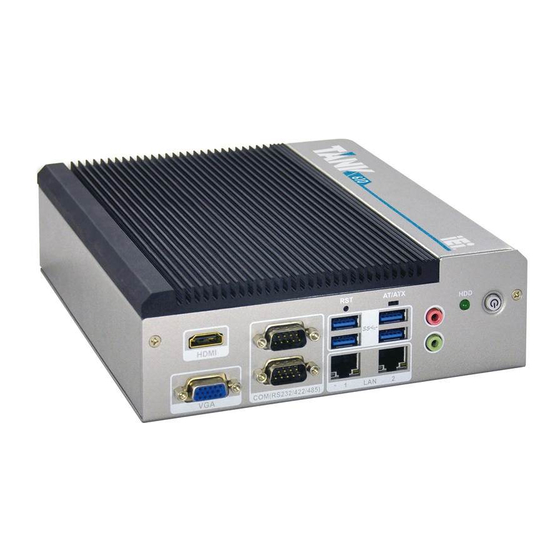
Page 15: Front Panel
TANK-610-BW Em be d d e d S ys te m 1.4 Fro n t P a n e l The front panel of the TANK-610-BW has the following features (Figure 1-2): Figure 1-2: TANK-610-BW Front Panel Connectors and buttons on the front panel include the following: ... -
Page 16: Rear Panel
TANK-610-BW Em be d d e d S ys te m 1.5 Re a r P a n e l The rear panel of the TANK-610-BW has the following features (Figure 1-2): Figure 1-3: TANK-610-BW Rear Panel Connectors and buttons on the front panel include the following: ... -
Page 17: Dimensions
TANK-610-BW Em be d d e d S ys te m 1.6 Dim e n s io n s The physical dimensions are shown below: Figure 1-4: Physical Dimensions (millimeters) P a g e 7... -
Page 18: Unpacking
TANK-610-BW Em be d d e d S ys te m Ch a p te r Un p a c kin g P a g e 8... -
Page 19: Unpacking
TANK-610-BW Em be d d e d S ys te m 2.1 Un pa c kin g To unpack the embedded system, follow the steps below: S te p 1: Use box cutters, a knife or a sharp pair of scissors that seals the top side of the external (second) box. -
Page 20: Table 2-1: Package List
TANK-610-BW Em be d d e d S ys te m Qu a n tity Ite m a n d P a rt Nu m b e r Im a g e Power Adapter Power Cord Wall Mounting Bracket Screws... -
Page 21: Optional Items
TANK-610-BW Em be d d e d S ys te m 2.3 Op tio n a l Ite m s The following are optional component(s) which may be separately purchased: AFLWK-19 (VESA 100 mount kit) EMB-WIFI-KIT01-R11 (1T1R Wi-Fi module kit for embedded system , IEEE802.11b/g/n,... -
Page 22: Installation
TANK-610-BW Em be d d e d S ys te m Ch a p te r In s ta lla tio n P a g e 12... -
Page 23: Anti - Static Precautions
Electrostatic discharge (ESD) can cause serious damage to electronic components, including the WAFER series motherboard and the power module. (Dry climates are especially susceptible to ESD.) It is therefore critical that whenever the TANK-610-BW is opened and any electrical component handled, the following anti-static precautions are strictly adhered to. -
Page 24: Hard Disk Drive (Hdd) Installation
Air Circulation: Make sure there is sufficient air circulation when installing the TANK-610-BW. The TANK-610-BW’s cooling vents must not be obstructed by any objects. Blocking the vents can cause overheating of the TANK-610-BW. Leave at least 5 cm of clearance around the TANK-610-BW to prevent overheating. ... -
Page 25: Figure 3-2: Hdd Bracket Retention Screws
TANK-610-BW Em be d d e d S ys te m Figure 3-2: HDD Bracket Retention Screws S te p 3: Slide the HDD to the HDD bracket and secure the HDD to the HDD bracket using four retention screws (Figure 3-3). -
Page 26: Wireless Lan Module Installation (Optional )
Remove the bottom surface. See Section 3.2. Remove the two knockout holes for antenna installation. The two knockout S te p 2: holes are located on the rear panel of the TANK-610-BW as shown in Figure 3-4. Figure 3-4: Knockout Holes for Wireless Antenna S te p 3: Locate the PCIe Mini slot (Figure 3-5). -
Page 27: Figure 3-6: Removing The Retention Screw
TANK-610-BW Em be d d e d S ys te m Figure 3-6: Removing the Retention Screw S te p 5: Insert into the socket at an angle. Line up the notch on the WLAN module with the notch on the slot. Slide the WLAN module into the slot at an angle of about 20º... -
Page 28: Figure 3-8: Securing Wlan Module And Connecting Rf Cables
TANK-610-BW Em be d d e d S ys te m Figure 3-8: Securing WLAN Module and Connecting RF Cables S te p 8: Remove the nut and washer from the SMA connector at the other end of the RF cable. -
Page 29: Mounting The System
TANK-610-BW Em be d d e d S ys te m 3.5 Mo u n tin g th e S ys te m There are two ways to mount the TANK-610-BW. The mounting instructions are described below. 3.5.1 Mo u n tin g with Mo u n tin g Bra c ke ts To mount the embedded system onto a wall or some other surface using the two mounting brackets, please follow the steps below. -
Page 30: Mounting With Vesa Mount Kit (Optional)
TANK-610-BW Em be d d e d S ys te m S te p 6: Insert four retention screws, two in each bracket, to secure the system to the wall. 3.5.2 Mo u n tin g with VES A Mo u n t Kit (Op tio n a l) To mount the embedded system onto a wall using the optional VESA 100 wall mount kit, please follow the steps below. -
Page 31: At/Atx Mode Selection
3.6 AT/ATX Mo d e S e le c tio n AT or ATX power mode can be used on the TANK-610-BW. The selection is made through an AT/ATX switch located on the bottom panel. To select AT mode or ATX mode, follow the steps below. -
Page 32: At Power Mode
3.6.2 ATX P owe r Mo d e With the ATX mode selected, the TANK-610-BW system goes in a standby mode when it is turned off. The system can be easily turned on via network or a power switch in standby mode. -
Page 33: Reset The System
TANK-610-BW Em be d d e d S ys te m 3.7 Re s e t th e S ys te m The reset button enables user to reboot the system when the system is turned on. To reboot the system, follow the steps below. -
Page 34: External Peripheral Device Connection
3.9.1 Au d io Co n n e c tio n The audio jacks on the external audio connector enable the TANK-610-BW to be connected to a stereo sound setup. To install the audio devices, follow the steps below. -
Page 35: Hdmi Device Connection
3.9.2 HDMI De vic e Co n n e c tio n The HDMI connector transmits a digital signal to compatible HDMI display devices such as a TV or computer screen. To connect the HDMI cable to the TANK-610-BW, follow the steps below. -
Page 36: Lan Connection
3.9.3 LAN Co n n e c tio n There are two external RJ-45 LAN connectors on the TANK-610-BW. The RJ-45 connector enables connection to an external network. To connect a LAN cable with an RJ-45 connector, please follow the instructions below. -
Page 37: Serial Device Connection
TANK-610-BW Em be d d e d S ys te m Figure 3-18: LAN Connection Insert the LAN cable RJ-45 connector. Once aligned, gently insert the LAN S te p 3: cable RJ-45 connector into the external interface. 3.9.4 S e ria l De vic e Co n n e c tio n There are six RS-232 connectors via DB-9, two RS-232/422/485 connectors via DB-9 for serial device connection. -
Page 38: Usb Device Connection
Step 0: 3.9.5 US B De vic e Co n n e c tio n There are four USB 3.0 connectors on the TANK-610-BW. To connect a USB device, please follow the instructions below. Locate the USB connectors. The locations of the USB connectors are shown S te p 1: in Chapter 1. -
Page 39: Vga Monitor Connection
3.9.6 VGA Mo n ito r Co n n e c tio n The TANK-610-BW has a single female DB-15 connector on the external peripheral interface panel. The DB-15 connector is connected to a CRT or VGA monitor. To connect a monitor to the TANK-610-BW, please follow the instructions below. -
Page 40: Figure 3-21: Vga Connector
TANK-610-BW Em be d d e d S ys te m Figure 3-21: VGA Connector Secure the connector. Secure the DB-15 VGA connector from the VGA S te p 4: monitor to the external interface by tightening the two retention screws on either side of the connector. -
Page 41: Bios
TANK-610-BW Em be d d e d S ys te m Ch a p te r BIOS P a g e 31... -
Page 42: Introduction
TANK-610-BW Em be d d e d S ys te m 4.1 In tro d u c tio n The BIOS is programmed onto the BIOS chip. The BIOS setup program allows changes to certain system settings. This chapter outlines the options that can be changed. -
Page 43: Getting Help
TANK-610-BW Em be d d e d S ys te m Ke y Fu n c tio n Esc key Main Menu – Quit and not save changes into CMOS Status Page Setup Menu and Option Page Setup Menu --... -
Page 44: Main
TANK-610-BW Em be d d e d S ys te m 4.2 Ma in The Main BIOS menu (BIOS Menu 1) appears when the BIOS Setup program is entered. The Main menu gives an overview of the basic system information. -
Page 45: Advanced
TANK-610-BW Em be d d e d S ys te m S ys te m Da te [xx/xx/xx] Use the System Date option to set the system date. Manually enter the day, month and year. S ys te m Tim e [xx:xx:xx] Use the System Time option to set the system time. -
Page 46: Acpi Settings
TANK-610-BW Em be d d e d S ys te m 4.3.1 ACP I S e ttin g s The ACPI Settings menu (BIOS Menu 3) configures the Advanced Configuration and Power Interface (ACPI) options. Aptio Setup Utility – Copyright (C) 2016 American Megatrends, Inc. -
Page 47: F81866 Super Io Configuration
TANK-610-BW Em be d d e d S ys te m 4.3.2 F81866 S u pe r IO Co nfig u ra tio n Use the F81866 Super IO Configuration menu (BIOS Menu 4) to set or change the configurations for the serial ports. -
Page 48: Change Settings [Auto]
TANK-610-BW Em be d d e d S ys te m 4.3.2.1.1 S e ria l P o rt 1 Co n fig u ra tio n S e ria l P o rt [En a b le d ] Use the Serial Port option to enable or disable the serial port. -
Page 49: Change Settings [Auto]
TANK-610-BW Em be d d e d S ys te m 4.3.2.1.2 S e ria l P o rt 2 Co n fig u ra tio n S e ria l P o rt [En a b le d ] Use the Serial Port option to enable or disable the serial port. -
Page 50: Change Settings [Auto]
TANK-610-BW Em be d d e d S ys te m 4.3.2.1.3 S e ria l P o rt 3 Co n fig u ra tio n S e ria l P o rt [En a b le d ] Use the Serial Port option to enable or disable the serial port. -
Page 51: Change Settings [Auto]
TANK-610-BW Em be d d e d S ys te m 4.3.2.1.4 S e ria l P o rt 4 Co n fig u ra tio n S e ria l P o rt [En a b le d ] Use the Serial Port option to enable or disable the serial port. -
Page 52: Change Settings [Auto]
TANK-610-BW Em be d d e d S ys te m 4.3.2.1.5 S e ria l P o rt 5 Co n fig u ra tio n S e ria l P o rt [En a b le d ] Use the Serial Port option to enable or disable the serial port. -
Page 53: Change Settings [Auto]
TANK-610-BW Em be d d e d S ys te m Enables serial port RS-232 support. RS232 EFAULT RS422 Enables serial port RS-422 support. RS485 Enables serial port RS-485 support. 4.3.2.1.6 S e ria l P o rt 6 Co n fig u ra tio n ... -
Page 54: H/W Monitor
TANK-610-BW Em be d d e d S ys te m Serial Port I/O port address is 2E0h and IO=2E0h; IRQ=3, 4, 5, 6, 7, 9, 10, 11, 12 the interrupt address is IRQ3, 4, 5, 6, 7, 9, 10, 11, 12 ... -
Page 55: It8528Sec Super Io Configuration
TANK-610-BW Em be d d e d S ys te m System Temperatures: CPU Temperature System Temperature 4.3.4 IT8528S EC S upe r IO Co n fig u ra tio n Use the IT8528SEC Super IO Configuration menu (BIOS Menu 7) to set or change the configurations for the serial ports. -
Page 56: Serial Port N Configuration
TANK-610-BW Em be d d e d S ys te m 4.3.4.1 S e ria l P o rt n Co n fig u ra tio n Use the Serial Port n Configuration menu (BIOS Menu 8) to configure the serial port n. -
Page 57: Serial Port [Enabled]
TANK-610-BW Em be d d e d S ys te m Serial Port I/O port address is 248h and IO=248h; IRQ=7 the interrupt address is IRQ7 IO=248h; IRQ=3, 4, Serial Port I/O port address is 248h and the interrupt address is IRQ3, 4, 5, 6, 7, 9,... -
Page 58: Rtc Wake Settings
TANK-610-BW Em be d d e d S ys te m Serial Port I/O port address is 258h and IO=258h; IRQ=7 the interrupt address is IRQ7 IO=248h; IRQ=3, 4, Serial Port I/O port address is 248h and the interrupt address is IRQ3, 4, 5, 6, 7, 9,... -
Page 59: Bios Menu 9: Rtc Wake Settings
TANK-610-BW Em be d d e d S ys te m Aptio Setup Utility – Copyright (C) 2016 American Megatrends, Inc. Advanced Wake system with Fixed Time [Disabled] Enable or disable System wake on alarm event. When enabled, System will... -
Page 60: Serial Port Console Redirection
TANK-610-BW Em be d d e d S ys te m 4.3.6 S e ria l P o rt Co n s o le Re d ire c tio n The Serial Port Console Redirection menu (BIOS Menu 10) allows the console redirection options to be configured. -
Page 61: Console Redirection Settings
TANK-610-BW Em be d d e d S ys te m Enabled the console redirection function Enabled 4.3.6.1 Co n s o le Re d ire c tio n S e ttin g s The Console Redirection Settings menu (BIOS Menu 11) allows the console redirection options to be configured. - Page 62 TANK-610-BW Em be d d e d S ys te m Bits p e r s e c o n d [115200] Use the Bits per second option to specify the transmission speed of the serial port. The transmission speed is 9600 9600 ...
-
Page 63: Iei Feature
TANK-610-BW Em be d d e d S ys te m Sto p Bits [1] Use the Stop Bits option to specify the number of stop bits used to indicate the end of a serial data packet. Communication with slow devices may require more than 1 stop bit. -
Page 64: Cpu Configuration
TANK-610-BW Em be d d e d S ys te m Au to Re c o ve ry Sta tu s [En a b le d ] Use Auto Recovery Status option to enable or disable the auto recovery status. - Page 65 TANK-610-BW Em be d d e d S ys te m Processor Type: Lists the brand name of the CPU being used CPU Signature: Lists the CPU signature value. Microcode Patch: Lists the microcode patch being used.
-
Page 66: Sata Configuration
TANK-610-BW Em be d d e d S ys te m 4.3.9 S ATA Co n fig u ra tio n Use the SATA Configuration menu (BIOS Menu 14) to change and/or set the configuration of the SATA devices installed in the system. -
Page 67: Usb Configuration
TANK-610-BW Em be d d e d S ys te m Enables the port as Hot Pluggable. Enabled 4.3.10 US B Co n fig u ra tio n Use the USB Configuration menu (BIOS Menu 15) to read USB configuration information and configure the USB settings. -
Page 68: Chipset
TANK-610-BW Em be d d e d S ys te m Legacy USB support enabled Enabled EFAULT Disabled Legacy USB support disabled Auto Legacy USB support disabled if no USB devices are connected 4.4 Ch ips e t Use the Chipset menu (BIOS Menu 16) to access the Host Bridge and South Bridge configuration menus. -
Page 69: North Bridge Configuration
TANK-610-BW Em be d d e d S ys te m 4.4.1 No rth Brid g e Co n fig u ra tio n Use the North Bridge menu (BIOS Menu 17) to configure the north bridge chipset.. Aptio Setup Utility – Copyright (C) 2016 American Megatrends, Inc. -
Page 70: Primary Display [Auto]
TANK-610-BW Em be d d e d S ys te m P rim a ry Dis p la y [Au to ] Use the Primary Display option to select the primary graphics controller the system uses. The following options are available: ... -
Page 71: South Bridge Configuration
TANK-610-BW Em be d d e d S ys te m 448M 480M 512M DVMT To ta l Gfx Me m [256M] Use the DVMT Total Gfx Mem option to select DVMT5.0 total graphic memory size used by the internal graphic device. -
Page 72: Security
TANK-610-BW Em be d d e d S ys te m Au d io Co n tro lle r [En a b le d ] Use the Audio Controller option to enable or disable the High Definition Audio controller. -
Page 73: Boot
TANK-610-BW Em be d d e d S ys te m 4.6 Bo o t Use the Boot menu (BIOS Menu 21) to configure system boot options. Aptio Setup Utility – Copyright (C) 2016 American Megatrends, Inc. Main Advanced Chipset... -
Page 74: Quiet Boot [Enabled]
TANK-610-BW Em be d d e d S ys te m Qu ie t Bo o t [En a b le d ] Use the Quiet Boot BIOS option to select the screen display when the system boots. ... -
Page 75: Exit
TANK-610-BW Em be d d e d S ys te m 4.7 Exit Use the Exit menu (BIOS Menu 22) to load default BIOS values, optimal failsafe values and to save configuration changes. Aptio Setup Utility – Copyright (C) 2016 American Megatrends, Inc. -
Page 76: Restore User Defaults
TANK-610-BW Em be d d e d S ys te m S a ve a s Us e r De fa u lts Use the Save as User Defaults option to save the changes done so far as user defaults. -
Page 77: A Regulatory Compliance
TANK-610-BW Em be d d e d S ys te m Ap p e n d ix Re g u la to ry Co m p lia n c e P a g e 67... - Page 78 TANK-610-BW Em be d d e d S ys te m DECLARATION OF CONFORMITY This equipment is in conformity with the following EU directives: EMC Directive (2004/108/EC, 2014/30/EU) Low-Voltage Directive (2006/95/EC, 2014/35/EU) RoHS II Directive (2011/65/EU, 2015/863/EU) ...
- Page 79 TANK-610-BW Em be d d e d S ys te m Deutsch [German] IEI Integration Corp, erklärt dieses Gerät entspricht den grundlegenden Anforderungen und den weiteren entsprechenden Vorgaben der Richtlinie 2014/53/EU. Eesti [Estonian] IEI Integration Corp deklareerib seadme seadme vastavust direktiivi 2014/53/EÜ...
- Page 80 TANK-610-BW Em be d d e d S ys te m Lietuvių [Lithuanian] IEI Integration Corp deklaruoja, kad šis įranga atitinka esminius reikalavimus ir kitas 2014/53/EU Direktyvos nuostatas. Nederlands [Dutch] IEI Integration Corp dat het toestel toestel in overeenstemming is met de essentiële eisen en de andere relevante bepalingen van richtlijn...
- Page 81 TANK-610-BW Em be d d e d S ys te m Slovensko [Slovenian] IEI Integration Corp izjavlja, da je ta opreme v skladu z bistvenimi zahtevami in ostalimi relevantnimi določili direktive 2014/53/EU. Slovensky [Slovak] IEI Integration Corp týmto vyhlasuje, že zariadenia spĺňa základné...
- Page 82 TANK-610-BW Em be d d e d S ys te m Federal Communication Commission Interference Statement This equipment has been assembled with components that comply with the limits for a Class B digital device, pursuant to Part 15 of the FCC Rules. These limits are designed to provide reasonable protection against harmful interference in a residential installation.
-
Page 83: B Safety Precautions
TANK-610-BW Em be d d e d S ys te m Appendix S a fe ty P re c a u tio n s P a g e 73... -
Page 84: General Safety Precautions
Do not apply voltage levels that exceed the specified voltage range. Doing so may cause fire and/or an electrical shock. Electric shocks can occur if the TANK-610-BW chassis is opened when the TANK-610-BW is running. Do not drop or insert any objects into the ventilation openings of the TANK-610-BW. -
Page 85: Anti-Static Precautions
Electrostatic discharge (ESD) can cause serious damage to electronic components, including the TANK-610-BW. Dry climates are especially susceptible to ESD. It is therefore critical that whenever the TANK-610-BW is opened and any of the electrical components are handled, the following anti-static precautions are strictly adhered to. -
Page 86: Product Disposal
When maintaining or cleaning the TANK-610-BW, please follow the guidelines below. B.2.1 Ma in te n a n c e a n d Cle a n in g Prior to cleaning any part or component of the TANK-610-BW, please read the details below. -
Page 87: Cleaning Tools
Some components in the TANK-610-BW may only be cleaned using a product specifically designed for the purpose. In such case, the product will be explicitly mentioned in the cleaning tips. Below is a list of items to use when cleaning the TANK-610-BW. ... -
Page 88: C Bios Options
TANK-610-BW Em be d d e d S ys te m Ap p e n d ix BIOS Op tio n s P a g e 78... - Page 89 TANK-610-BW Em be d d e d S ys te m Below is a list of BIOS configuration options in the BIOS chapter. System Date [xx/xx/xx] ......................35 System Time [xx:xx:xx] .......................35 ACPI Sleep State [S1 (CPU Stop Clock)] ................36 ...
- Page 90 TANK-610-BW Em be d d e d S ys te m SATA Controller [Enabled] ....................56 SATA Mode Selection [AHCI] ....................56 Hot Plug [Disabled] ......................56 USB Devices .........................57 Legacy USB Support [Enabled] ..................57 Primary Display [Auto] ......................60 ...
-
Page 91: D Terminology
TANK-610-BW Em be d d e d S ys te m Ap p e n d ix Te rm in o lo g y P a g e 81... - Page 92 TANK-610-BW Em be d d e d S ys te m AC ’97 Audio Codec 97 (AC’97) refers to a codec standard developed by Intel® in 1997. ACP I Advanced Configuration and Power Interface (ACPI) is an OS-directed configuration, power management, and thermal management interface.
- Page 93 TANK-610-BW Em be d d e d S ys te m Direct Memory Access (DMA) enables some peripheral devices to bypass the system processor and communicate directly with the system memory. DIMM Dual Inline Memory Modules are a type of RAM that offer a 64-bit data bus and have separate electrical contacts on each side of the module.
- Page 94 TANK-610-BW Em be d d e d S ys te m Liquid crystal display (LCD) is a flat, low-power display device that consists of two polarizing plates with a liquid crystal panel in between. LVDS Low-voltage differential signaling (LVDS) is a dual-wire, high-speed differential electrical signaling system commonly used to connect LCD displays to a computer.
-
Page 95: E Hazardous Materials Disclosure
TANK-610-BW Em be d d e d S ys te m Ap p e n d ix Ha za rd o u s Ma te ria ls Dis c lo s u re P a g e 85... -
Page 96: Ercury
TANK-610-BW Em be d d e d S ys te m E.1 Ha za rd o u s Ma te ria ls Dis c lo s u re Ta ble for IP B P ro d u c ts Ce rtifie d a s Ro HS Co m p lia n t Un d e r 2011/65/EU With ou t... - Page 97 TANK-610-BW Em be d d e d S ys te m P a rt Na m e To xic o r Ha za rd o u s S u b s ta n c e s a n d Ele m e n ts...
- Page 98 TANK-610-BW Em be d d e d S ys te m 此附件旨在确保本产品符合中国 RoHS 标准。以下表格标示此产品中某有毒物质的含量符 合中国 RoHS 标准规定的限量要求。 本产品上会附有”环境友好使用期限”的标签,此期限是估算这些物质”不会有泄漏或突变”的 年限。本产品可能包含有较短的环境友好使用期限的可替换元件,像是电池或灯管,这些元 件将会单独标示出来。 部件名称 有毒有害物质或元素 铅 汞 镉 六价铬 多溴联苯 多溴二苯 醚 (P b ) (Hg ) (Cd ) (CR(VI)) (P BB) (P BDE) 壳体...
Need help?
Do you have a question about the TANK-610-BW and is the answer not in the manual?
Questions and answers