Table of Contents

Related Manuals for IEI Technology TANK-610-BW


Summary of Contents for IEI Technology TANK-610-BW
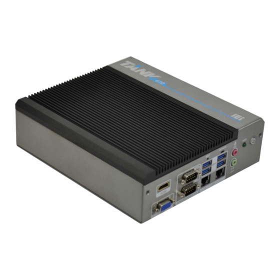
- Page 1 TANK-610-BW Embedded System MODEL: TANK-610-BW Fanless Embedded System with Intel® Celeron® N3160 processor, VGA, HDMI, Two Gigabit Ethernet, Four USB 3.0, RS-232/422/485, RoHS Compliant User Manual Page i Rev. 1.03 – May 25, 2021...
- Page 2 TANK-610-BW Embedded System Revision Date Version Changes May 25, 2021 1.03 Updated Section 2.2: Packing List November 27, 2017 1.02 Add Chapter 4: System Motherboard April 10, 2017 1.01 Add Appendix E: Watchdog Timer June 6, 2016 1.00 Initial release...
- Page 3 TANK-610-BW Embedded System Copyright COPYRIGHT NOTICE The information in this document is subject to change without prior notice in order to improve reliability, design and function and does not represent a commitment on the part of the manufacturer. In no event will the manufacturer be liable for direct, indirect, special, incidental, or consequential damages arising out of the use or inability to use the product or documentation, even if advised of the possibility of such damages.
- Page 4 TANK-610-BW Embedded System Manual Conventions WARNING Warnings appear where overlooked details may cause damage to the equipment or result in personal injury. Warnings should be taken seriously. CAUTION Cautionary messages should be heeded to help reduce the chance of losing data or damaging the product.
-
Page 5: Table Of Contents
TANK-610-BW Embedded System Table of Contents 1 INTRODUCTION ......................1 1.1 O ........................2 VERVIEW 1.2 F ........................2 EATURES 1.3 T ..................3 ECHNICAL PECIFICATIONS 1.4 F ......................5 RONT ANEL 1.5 R ....................... 6 ANEL 1.6 D ....................... 7 IMENSIONS 2 UNPACKING ......................... - Page 6 TANK-610-BW Embedded System 4.2.1 Battery Connector (BAT1) ................26 4.2.2 BIOS Programming Connector (SPI1) ............26 4.2.3 Digital I/O Connector (DIO1) ................. 27 4.2.4 Debug Connector (DEBUGCN1) ..............27 4.2.5 FPC Connector (CN1) ..................27 4.2.6 EC Programming Connector (JSPI1) .............. 28 4.2.7 Keyboard/Mouse Connector (KB_MS_CN1) ...........
- Page 7 TANK-610-BW Embedded System 5.1.5 BIOS Menu Bar ....................39 5.2 M ........................40 5.3 A ....................... 41 DVANCED 5.3.1 ACPI Settings ....................42 5.3.2 F81866 Super IO Configuration ..............43 5.3.2.1 Serial Port n Configuration ............... 43 5.3.2.1.1 Serial Port 1 Configuration ..............44 5.3.2.1.2 Serial Port 2 Configuration ..............
- Page 8 TANK-610-BW Embedded System B.1.1 General Safety Precautions ................79 B.1.2 Anti-static Precautions ..................80 B.1.3 Product Disposal ..................... 81 B.2 M ............81 AINTENANCE AND LEANING RECAUTIONS B.2.1 Maintenance and Cleaning ................82 B.2.2 Cleaning Tools ....................82 C BIOS OPTIONS ......................83 D WATCHDOG TIMER ....................
- Page 9 TANK-610-BW Embedded System List of Figures Figure 1-1: TANK-610-BW ......................2 Figure 1-2: TANK-610-BW Front Panel ..................5 Figure 1-3: TANK-610-BW Rear Panel ..................6 Figure 1-4: Physical Dimensions (millimeters) ................7 Figure 3-1: Remove Retention Screws (Bottom Panel) ............13 Figure 3-2: HDD Bracket Retention Screws ................
- Page 10 TANK-610-BW Embedded System List of Tables Table 1-1: Technical Specifications ....................4 Table 2-1: Package List ........................ 10 Table 2-2: Optional Items ......................10 Table 4-1: Peripheral Interface Connectors ................26 Table 4-2: Battery Connector Pinouts (BAT1) ................26 Table 4-3: BIOS Programming Connector Pinouts (SPI1) ............26 Table 4-4: Digital I/O Connector Pinouts (DIO1) ................
- Page 11 TANK-610-BW Embedded System Table 4-28: M-SATA Auto-detect Jumper (MIMI_SW1 ) ............36 Table 4-29: System Reset Button (RST1) ................... 36 Table 5-1: BIOS Navigation Keys ....................39 Page xi...
- Page 12 TANK-610-BW Embedded System BIOS Menus BIOS Menu 1: Main ........................40 BIOS Menu 2: Advanced ......................41 BIOS Menu 3: ACPI Configuration ....................42 BIOS Menu 4: F81866 Super IO Configuration ................43 BIOS Menu 5: Serial Port n Configuration Menu ............... 43 BIOS Menu 6: Hardware Health Configuration ................
-
Page 13: Introduction
TANK-610-BW Embedded System Chapter Introduction Page 1... -
Page 14: Overview
204-pin DDR3L 1.35V SDRAM SO-DIMMs (system max 8GB). The TANK-610-BW supports dual independent display via one VGA port and one HDMI port. The TANK-610-BW has two GbE LAN ports, four USB 3.0 ports, six RS-232 connectors via DB-9 and two RS-232/422/485 connectors via DB-9. -
Page 15: Technical Specifications
TANK-610-BW Embedded System 1.3 Technical Specifications The TANK-610-BW technical specifications are listed in Table 1-1. Specifications Chassis Black C + Silver Color Dimension (WxDxH) 184 x 200.6 x 58.2 mm System Fan Fanless Chassis Construction Extruded aluminum alloy Motherboard Intel® Celeron® N3160 processor (up to 2.24GHz, quad-core, 2MB cache, TDP=6W) -
Page 16: Table 1-1: Technical Specifications
TANK-610-BW Embedded System Specifications 1 x 802.11 b/g/n (optional) Wireless Expansions 1 x Full-size PCIe Mini slot (supports mSATA, co-lay SATA) 1 x Half-size PCIe Mini slot Power Power Input DC jack: 9 V~36 V DC Power Consumption 12 V@1.49 A (Intel® Celeron® N3160 with 4 GB DDR3L memory) -
Page 17: Front Panel
TANK-610-BW Embedded System 1.4 Front Panel The front panel of the TANK-610-BW has the following features (Figure 1-2): Figure 1-2: TANK-610-BW Front Panel Connectors and buttons on the front panel include the following: 1 x AT/ATX mode switch ... -
Page 18: Rear Panel
TANK-610-BW Embedded System 1.5 Rear Panel The rear panel of the TANK-610-BW has the following features (Figure 1-2): Figure 1-3: TANK-610-BW Rear Panel Connectors and buttons on the front panel include the following: 1 x 9 V ~ 36 V DC Jack ... -
Page 19: Dimensions
TANK-610-BW Embedded System 1.6 Dimensions The physical dimensions are shown below: Figure 1-4: Physical Dimensions (millimeters) Page 7... -
Page 20: Unpacking
TANK-610-BW Embedded System Chapter Unpacking Page 8... -
Page 21: Unpacking
If any of the components listed in the checklist below are missing, do not proceed with the installation. Contact the IEI reseller or vendor the TANK-610-BW was purchased from or contact an IEI sales representative directly by sending an email to sales@ieiworld.com. -
Page 22: Optional Items
TANK-610-BW Embedded System Quantity Item and Part Number Image Power Adapter Power Cord Wall Mounting Bracket Screws Wall Mounting Brackets Screw Set Table 2-1: Package List 2.3 Optional Items The following are optional component(s) which may be separately purchased: AFLWK-19... -
Page 23: Installation
TANK-610-BW Embedded System Chapter Installation Page 11... -
Page 24: Anti-Static Precautions
Electrostatic discharge (ESD) can cause serious damage to electronic components, including the WAFER series motherboard and the power module. (Dry climates are especially susceptible to ESD.) It is therefore critical that whenever the TANK-610-BW is opened and any electrical component handled, the following anti-static precautions are strictly adhered to. -
Page 25: Hard Disk Drive (Hdd) Installation
Air Circulation: Make sure there is sufficient air circulation when installing the TANK-610-BW. The TANK-610-BW’s cooling vents must not be obstructed by any objects. Blocking the vents can cause overheating of the TANK-610-BW. Leave at least 5 cm of clearance around the TANK-610-BW to prevent overheating. ... -
Page 26: Figure 3-2: Hdd Bracket Retention Screws
TANK-610-BW Embedded System Figure 3-2: HDD Bracket Retention Screws Step 3: Slide the HDD to the HDD bracket and secure the HDD to the HDD bracket using four retention screws (Figure 3-3). Figure 3-3: Inserting the HDD Step 4: Reinstall the bottom cover. -
Page 27: Wireless Lan Module Installation (Optional)
Remove the bottom surface. See Section 3.3. Step 2: Remove the two knockout holes for antenna installation. The two knockout holes are located on the rear panel of the TANK-610-BW as shown in Figure 3-4. Figure 3-4: Knockout Holes for Wireless Antenna Step 3: Locate the PCIe Mini slot (Figure 3-5). -
Page 28: Figure 3-6: Removing The Retention Screw
TANK-610-BW Embedded System Figure 3-6: Removing the Retention Screw Step 5: Insert into the socket at an angle. Line up the notch on the WLAN module with the notch on the slot. Slide the WLAN module into the slot at an angle of about 20º... -
Page 29: Figure 3-8: Securing Wlan Module And Connecting Rf Cables
TANK-610-BW Embedded System Figure 3-8: Securing WLAN Module and Connecting RF Cables Step 8: Remove the nut and washer from the SMA connector at the other end of the RF cable. Step 9: Insert the SMA connector to the antenna connector holes on the rear panel. -
Page 30: Mounting The System
TANK-610-BW Embedded System 3.5 Mounting the System There are two ways to mount the TANK-610-BW. The mounting instructions are described below. 3.5.1 Mounting with Mounting Brackets To mount the embedded system onto a wall or some other surface using the two mounting brackets, please follow the steps below. -
Page 31: Mounting With Vesa Mount Kit (Optional)
(Figure 3-12). Step 7: Align the mounting screws on the TANK-610-BW bottom panel with the mounting holes on the bracket. Step 8:... -
Page 32: At/Atx Mode Selection
Figure 3-12: Mount the Embedded System 3.6 AT/ATX Mode Selection AT or ATX power mode can be used on the TANK-610-BW. The selection is made through an AT/ATX switch located on the bottom panel. To select AT mode or ATX mode, follow the steps below. -
Page 33: At Power Mode
Manufacturing shop flow 3.6.2 ATX Power Mode With the ATX mode selected, the TANK-610-BW system goes in a standby mode when it is turned off. The system can be easily turned on via network or a power switch in standby mode. -
Page 34: Reset The System
TANK-610-BW Embedded System 3.7 Reset the System The reset button enables user to reboot the system when the system is turned on. To reboot the system, follow the steps below. Step 1: Locate the reset button on the bottom panel (Figure 3-14). -
Page 35: Figure 3-15: Power Button
TANK-610-BW Embedded System Figure 3-15: Power Button Page 23... -
Page 36: System Motherboard
TANK-610-BW Embedded System Chapter System Motherboard Page 24... -
Page 37: Overview
TANK-610-BW Embedded System 4.1 Overview This chapter details all the jumpers and connectors of the system motherboard. 4.1.1 Layout The figures below show all the connectors and jumpers of the system motherboard. The Pin 1 locations of the on-board connectors are also indicated in the diagram below. -
Page 38: Internal Peripheral Connectors
TANK-610-BW Embedded System 4.2 Internal Peripheral Connectors The table below shows a list of the internal peripheral interface connectors on the system motherboard. Pinouts of these connectors can be found in the following sections. Connector Type Label Battery connector 2-pin wafer... -
Page 39: Digital I/O Connector (Dio1)
TANK-610-BW Embedded System 4.2.3 Digital I/O Connector (DIO1) PIN NO. DESCRIPTION PIN NO. DESCRIPTION DOUT3 DOUT2 DOUT1 DOUT0 DIN3 DIN2 DIN1 DIN0 Table 4-4: Digital I/O Connector Pinouts (DIO1) 4.2.4 Debug Connector (DEBUGCN1) PIN NO. DESCRIPTION PIN NO. DESCRIPTION BUF_PLT_RST#... -
Page 40: Ec Programming Connector (Jspi1)
TANK-610-BW Embedded System 4.2.6 EC Programming Connector (JSPI1) PIN NO. DESCRIPTION PIN NO. DESCRIPTION +V3.3M_SPI_CON_EC SPI_CS#0_CN_EC SPI_SO_SW_EC SPI_CLK_SW_EC SPI_SI_SW_EC Table 4-7: EC Programming Connector Pinouts (JSPI1) 4.2.7 Keyboard/Mouse Connector (KB_MS_CN1) PIN NO. DESCRIPTION PIN NO. DESCRIPTION +5V_KBMS MSDATA MSCLK KBDATA... -
Page 41: Usb 2.0 Connectors (Usb1)
TANK-610-BW Embedded System 4.2.10 USB 2.0 Connectors (USB1) PIN NO. DESCRIPTION PIN NO. DESCRIPTION +VCC_USB34 -DATA_USB3 +DATA_USB4 +DATA_USB3 -DATA_USB4 +VCC_USB34 Table 4-11: USB 2.0 Connectors Pinouts (USB1) 4.2.11 USB 2.0 Connectors (USB2) PIN NO. DESCRIPTION PIN NO. DESCRIPTION +VCC_USB12 -DATA_USB1... -
Page 42: Audio Jack (Jaudio1)
TANK-610-BW Embedded System Connector Type Label RS-232 serial port connectors DB-78 VGA connector DB-15 VGA1 Table 4-13: Rear Panel Connectors 4.3.1 Audio Jack (JAUDIO1) PIN NO. DESCRIPTION PIN NO. DESCRIPTION Analog_GND LMIC1-L Analog_GND MIC1-JD LMIC1-R LINE_OUTL Analog_GND FRONT-JD LINE_OUTR Table 4-14: Audio Jack Pinouts (JAUDIO1) 4.3.2 Ethernet and USB2.0 Connectors (USB_LAN1) -
Page 43: Ethernet And Usb2.0 Connectors (Usb_Lan2)
TANK-610-BW Embedded System USB3_TX1_DP_C +USB3_PWR1 USB20_C_N1 USB20_C_P1 USB3_RX2_DN USB3_RX2_DP USB3_TX2_DN_C USB3_TX2_DP_C Table 4-15: Ethernet and USB2.0 Connectors Pinouts (USB_LAN1) 4.3.3 Ethernet and USB2.0 Connectors (USB_LAN2) PIN NO. DESCRIPTION PIN NO. DESCRIPTION 1_5VLAN2 TRD2P0 TRD2N0 TRD2P1 TRD2N1 TRD2P2 TRD2N2 TRD2P3 TRD2N3... -
Page 44: Hdmi Connector (Hdmi1)
TANK-610-BW Embedded System 4.3.4 HDMI Connector (HDMI1) PIN NO. DESCRIPTION PIN NO. DESCRIPTION HDMI1_DATA2_C HDMI1_DATA2#_C HDMI1_DATA1_C HDMI1_DATA1#_C HDMI1_DATA0_C HDMI1_DATA0#_C HDMI1_CLK_C HDMI1_CLK#_C HDMI1_SCL HDMI1_SDA HDMI1_PWR HDMI1_HPD Table 4-17: HDMI Connector Pinouts (HDMI1) 4.3.5 Power Connector (DC_IN1) PIN NO. DESCRIPTION PIN NO. -
Page 45: Serial Port Connector (Com1-2)
TANK-610-BW Embedded System 4.3.7 RS-232 Serial Port Connector (COM1-2) PIN NO. DESCRIPTION PIN NO. DESCRIPTION -NDCD1 NSIN1 NSOUT1 -NDTR1 -NDSR1 -NRTS1 -NCTS1 -XRI1 -NDCD2 NSIN2 NSOUT2 -NDTR2 -NDSR2 -NRTS2 -NCTS2 -XRI2 Table 4-20: RS-232 Serial Port Connector Pinouts (COM1-2) 4.3.8 RS-232 Serial Port Connector (COM3-4) PIN NO. -
Page 46: Serial Port Connector (Com5-6)
TANK-610-BW Embedded System -NRTS3 -NCTS3 -XRI3 -NDCD4 NSIN4 NSOUT4 -NDTR4 -NDSR4 -NRTS4 -NCTS4 -XRI4 Table 4-22: RS-232 Serial Port Connector Pinouts (COM3-4) 4.3.10 RS-232 Serial Port Connector (COM5-6) PIN NO. RS-232 RS-422 RS-485 COM5_DCD# TXD422# TXD485# COM5_SIN# TXD422+ TXD485+ COM5_SOUT#... -
Page 47: Vga Connector (Vga1)
TANK-610-BW Embedded System 4.3.11 VGA Connector (VGA1) PIN NO. DESCRIPTION PIN NO. DESCRIPTION VGA1_BR VGA1_BG VGA1_BB VGA1_VCC VGA1_PLUG# VGA1_DDC_SDA_C VGA1_HSYNC VGA1_VSYNC VGA1_DDC_SCL_C Table 4-24: VGA Connector Pinouts (VGA1) 4.4 Jumper Settings The buttons, jumper and switch on the system motherboard are listed in Table 4-25. -
Page 48: Clear Cmos Button (J_Cmos1)
TANK-610-BW Embedded System 4.4.2 Clear CMOS Button (J_CMOS1) Setting Description Open Normal Operation (Default) Push Clear CMOS Setup Table 4-27: Clear CMOS Button (J_CMOS1) 4.4.3 M-SATA Auto-detect Jumper (MIMI_SW1) Setting Description Open Auto detect Short Disable M-SATA Table 4-28: M-SATA Auto-detect Jumper (MIMI_SW1 ) 4.4.4 System Reset Button (RST1) -
Page 49: Bios
TANK-610-BW Embedded System Chapter BIOS Page 37... -
Page 50: Introduction
TANK-610-BW Embedded System 5.1 Introduction The BIOS is programmed onto the BIOS chip. The BIOS setup program allows changes to certain system settings. This chapter outlines the options that can be changed. 5.1.1 Starting Setup The UEFI BIOS is activated when the computer is turned on. The setup program can be activated in one of two ways. -
Page 51: Getting Help
TANK-610-BW Embedded System Function Esc key Main Menu – Quit and not save changes into CMOS Status Page Setup Menu and Option Page Setup Menu -- Exit current page and return to Main Menu General help, only for Status Page Setup Menu and Option... -
Page 52: Main
TANK-610-BW Embedded System 5.2 Main The Main BIOS menu (BIOS Menu 1) appears when the BIOS Setup program is entered. The Main menu gives an overview of the basic system information. Aptio Setup Utility – Copyright (C) 2016 American Megatrends, Inc. -
Page 53: Advanced
TANK-610-BW Embedded System System Date [xx/xx/xx] Use the System Date option to set the system date. Manually enter the day, month and year. System Time [xx:xx:xx] Use the System Time option to set the system time. Manually enter the hours, minutes and seconds. -
Page 54: Acpi Settings
TANK-610-BW Embedded System 5.3.1 ACPI Settings The ACPI Settings menu (BIOS Menu 3) configures the Advanced Configuration and Power Interface (ACPI) options. Aptio Setup Utility – Copyright (C) 2016 American Megatrends, Inc. Advanced ACPI Settings Select the highest ACPI sleep state the system... -
Page 55: F81866 Super Io Configuration
TANK-610-BW Embedded System 5.3.2 F81866 Super IO Configuration Use the F81866 Super IO Configuration menu (BIOS Menu 4) to set or change the configurations for the serial ports. Aptio Setup Utility – Copyright (C) 2016 American Megatrends, Inc. Advanced F81866 Super IO Configuration... -
Page 56: Serial Port 1 Configuration
TANK-610-BW Embedded System 5.3.2.1.1 Serial Port 1 Configuration Serial Port [Enabled] Use the Serial Port option to enable or disable the serial port. Disabled Disable the serial port Enable the serial port Enabled EFAULT Change Settings [Auto] Use the Change Settings option to change the serial port IO port address and interrupt address. -
Page 57: Serial Port 2 Configuration
TANK-610-BW Embedded System 5.3.2.1.2 Serial Port 2 Configuration Serial Port [Enabled] Use the Serial Port option to enable or disable the serial port. Disabled Disable the serial port Enable the serial port Enabled EFAULT Change Settings [Auto] Use the Change Settings option to change the serial port IO port address and interrupt address. -
Page 58: Serial Port 3 Configuration
TANK-610-BW Embedded System 5.3.2.1.3 Serial Port 3 Configuration Serial Port [Enabled] Use the Serial Port option to enable or disable the serial port. Disabled Disable the serial port Enable the serial port Enabled EFAULT Change Settings [Auto] Use the Change Settings option to change the serial port IO port address and interrupt address. -
Page 59: Serial Port 4 Configuration
TANK-610-BW Embedded System 5.3.2.1.4 Serial Port 4 Configuration Serial Port [Enabled] Use the Serial Port option to enable or disable the serial port. Disabled Disable the serial port Enable the serial port Enabled EFAULT Change Settings [Auto] Use the Change Settings option to change the serial port IO port address and interrupt address. -
Page 60: Serial Port 5 Configuration
TANK-610-BW Embedded System 5.3.2.1.5 Serial Port 5 Configuration Serial Port [Enabled] Use the Serial Port option to enable or disable the serial port. Disabled Disable the serial port Enable the serial port Enabled EFAULT Change Settings [Auto] Use the Change Settings option to change the serial port IO port address and interrupt address. -
Page 61: Serial Port 6 Configuration
TANK-610-BW Embedded System RS232 Enables serial port RS-232 support. EFAULT Enables serial port RS-422 support. RS422 RS485 Enables serial port RS-485 support. 5.3.2.1.6 Serial Port 6 Configuration Serial Port [Enabled] Use the Serial Port option to enable or disable the serial port. -
Page 62: H/W Monitor
TANK-610-BW Embedded System IO=2E0h; IRQ=3, 4, Serial Port I/O port address is 2E0h and 5, 6, 7, 9, 10, 11, 12 the interrupt address is IRQ3, 4, 5, 6, 7, 9, 10, 11, 12 Device Mode [RS232] Use the Device Mode option to select the serial port mode. -
Page 63: It8528Sec Super Io Configuration
TANK-610-BW Embedded System System Temperatures: CPU Temperature System Temperature 5.3.4 IT8528SEC Super IO Configuration Use the IT8528SEC Super IO Configuration menu (BIOS Menu 7) to set or change the configurations for the serial ports. Aptio Setup Utility – Copyright (C) 2016 American Megatrends, Inc. -
Page 64: Serial Port N Configuration
TANK-610-BW Embedded System 5.3.4.1 Serial Port n Configuration Use the Serial Port n Configuration menu (BIOS Menu 8) to configure the serial port n. Aptio Setup Utility – Copyright (C) 2016 American Megatrends, Inc. Advanced Serial Port n Configuration Enable or Disable Serial... -
Page 65: Serial Port 8 Configuration
TANK-610-BW Embedded System IO=248h; IRQ=7 Serial Port I/O port address is 248h and the interrupt address is IRQ7 Serial Port I/O port address is 248h and IO=248h; IRQ=3, 4, the interrupt address is IRQ3, 4, 5, 6, 7, 9,... -
Page 66: Rtc Wake Settings
TANK-610-BW Embedded System IO=258h; IRQ=7 Serial Port I/O port address is 258h and the interrupt address is IRQ7 Serial Port I/O port address is 248h and IO=248h; IRQ=3, 4, the interrupt address is IRQ3, 4, 5, 6, 7, 9,... - Page 67 TANK-610-BW Embedded System Aptio Setup Utility – Copyright (C) 2016 American Megatrends, Inc. Advanced Wake system with Fixed Time [Disabled] Enable or disable System wake on alarm event. When enabled, System will wake on the dat::hr::min::sec specified ---------------------- : Select Screen ↑...
-
Page 68: Serial Port Console Redirection
TANK-610-BW Embedded System 5.3.6 Serial Port Console Redirection The Serial Port Console Redirection menu (BIOS Menu 10) allows the console redirection options to be configured. Console redirection allows users to maintain a system remotely by re-directing keyboard input and text output through the serial port. -
Page 69: Console Redirection Settings
TANK-610-BW Embedded System Enabled Enabled the console redirection function 5.3.6.1 Console Redirection Settings The Console Redirection Settings menu (BIOS Menu 11) allows the console redirection options to be configured. The option is active when Console Redirection option is enabled. - Page 70 TANK-610-BW Embedded System Bits per second [115200] Use the Bits per second option to specify the transmission speed of the serial port. The transmission speed is 9600 9600 The transmission speed is 19200 19200 38400 The transmission speed is 38400 ...
-
Page 71: Iei Feature
TANK-610-BW Embedded System Stop Bits [1] Use the Stop Bits option to specify the number of stop bits used to indicate the end of a serial data packet. Communication with slow devices may require more than 1 stop bit. -
Page 72: Cpu Configuration
TANK-610-BW Embedded System Auto Recovery Status [Enabled] Use Auto Recovery Status option to enable or disable the auto recovery status. Disabled the auto recovery status. Disabled EFAULT Enabled the auto recovery status. Enabled Recovery from Local [Disabled] Use Recovery from Local option to enable or disable recovery from local function.. - Page 73 TANK-610-BW Embedded System Processor Type: Lists the brand name of the CPU being used CPU Signature: Lists the CPU signature value. Microcode Patch: Lists the microcode patch being used. Max CPU Speed: Lists the maximum CPU processing speed.
-
Page 74: Sata Configuration
TANK-610-BW Embedded System 5.3.9 SATA Configuration Use the SATA Configuration menu (BIOS Menu 14) to change and/or set the configuration of the SATA devices installed in the system. Aptio Setup Utility – Copyright (C) 2016 American Megatrends, Inc. Advanced SATA Configuration Enable/Disable SATA Device. -
Page 75: Usb Configuration
TANK-610-BW Embedded System Enabled Enables the port as Hot Pluggable. 5.3.10 USB Configuration Use the USB Configuration menu (BIOS Menu 15) to read USB configuration information and configure the USB settings. Aptio Setup Utility – Copyright (C) 2016 American Megatrends, Inc. -
Page 76: Chipset
TANK-610-BW Embedded System Enabled Legacy USB support enabled EFAULT Legacy USB support disabled Disabled Auto Legacy USB support disabled if no USB devices are connected 5.4 Chipset Use the Chipset menu (BIOS Menu 16) to access the Host Bridge and South Bridge configuration menus. -
Page 77: North Bridge Configuration
TANK-610-BW Embedded System 5.4.1 North Bridge Configuration Use the North Bridge menu (BIOS Menu 17) to configure the north bridge chipset.. Aptio Setup Utility – Copyright (C) 2016 American Megatrends, Inc. Chipset > Intel IGD Configuration Config Intel IGD Settings. - Page 78 TANK-610-BW Embedded System Primary Display [Auto] Use the Primary Display option to select the primary graphics controller the system uses. The following options are available: Auto Default PCIe Primary IGFX Boot Display [Auto] Use the Primary IGFX Boot Display option to select the display device used by the system when it boots.
-
Page 79: South Bridge Configuration
TANK-610-BW Embedded System 448M 480M 512M DVMT Total Gfx Mem [256M] Use the DVMT Total Gfx Mem option to select DVMT5.0 total graphic memory size used by the internal graphic device. The following options are available: ... -
Page 80: Security
TANK-610-BW Embedded System Audio Controller [Enabled] Use the Audio Controller option to enable or disable the High Definition Audio controller. The onboard High Definition Audio controller is disabled Disabled onboard High Definition Audio controller Enabled EFAULT automatically detected and enabled 5.5 Security... -
Page 81: Boot
TANK-610-BW Embedded System 5.6 Boot Use the Boot menu (BIOS Menu 21) to configure system boot options. Aptio Setup Utility – Copyright (C) 2016 American Megatrends, Inc. Main Advanced Chipset Boot Security Save & Exit Boot Configuration Select the keyboard... - Page 82 TANK-610-BW Embedded System Quiet Boot [Enabled] Use the Quiet Boot BIOS option to select the screen display when the system boots. Normal POST messages displayed Disabled OEM Logo displayed instead of POST messages Enabled EFAULT Boot Option filter [Legacy only] Use the Boot Option filter option to control legacy/UEFI ROMs priority.
-
Page 83: Exit
TANK-610-BW Embedded System 5.7 Exit Use the Exit menu (BIOS Menu 22) to load default BIOS values, optimal failsafe values and to save configuration changes. Aptio Setup Utility – Copyright (C) 2016 American Megatrends, Inc. Main Advanced Chipset Boot Security Save &... - Page 84 TANK-610-BW Embedded System Save as User Defaults Use the Save as User Defaults option to save the changes done so far as user defaults. Restore User Defaults Use the Restore User Defaults option to restore the user defaults to all the setup options.
-
Page 85: A Regulatory Compliance
TANK-610-BW Embedded System Appendix Regulatory Compliance Page 73... - Page 86 TANK-610-BW Embedded System DECLARATION OF CONFORMITY This equipment is in conformity with the following EU directives: EMC Directive 2014/30/EU Low-Voltage Directive 2014/35/EU RoHS II Directive 2015/863/EU If the user modifies and/or install other devices in the equipment, the CE conformity declaration may no longer apply.
- Page 87 TANK-610-BW Embedded System Ελληνική [Greek] IEI Integration Corp ΔΗΛΩΝΕΙ ΟΤΙ ΕΞΟΠΛΙΣΜΟΣ ΣΥΜΜΟΡΦΩΝΕΤΑΙ ΠΡΟΣ ΤΙΣ ΟΥΣΙΩΔΕΙΣ ΑΠΑΙΤΗΣΕΙΣ ΚΑΙ ΤΙΣ ΛΟΙΠΕΣ ΣΧΕΤΙΚΕΣ ΔΙΑΤΑΞΕΙΣ ΤΗΣ ΟΔΗΓΙΑΣ 1999/5/ΕΚ. Français [French] IEI Integration Corp déclare que l'appareil est conforme aux exigences essentielles et aux autres dispositions pertinentes de la directive 1999/5 CE.
- Page 88 TANK-610-BW Embedded System Slovensko [Slovenian] IEI Integration Corp izjavlja, da je ta opreme v skladu z bistvenimi zahtevami in ostalimi relevantnimi določili direktive 1999/5/ES. Slovensky [Slovak] IEI Integration Corp týmto vyhlasuje, že zariadenia spĺňa základné požiadavky a všetky príslušné ustanovenia Smernice 199 /5/ES.
- Page 89 TANK-610-BW Embedded System FCC WARNING This equipment complies with Part 15 of the FCC Rules. Operation is subject to the following two conditions: This device may not cause harmful interference, and This device must accept any interference received, including interference that may cause undesired operation.
-
Page 90: B Safety Precautions
TANK-610-BW Embedded System Appendix Safety Precautions Page 78... -
Page 91: Safety Precautions
Do not apply voltage levels that exceed the specified voltage range. Doing so may cause fire and/or an electrical shock. Electric shocks can occur if the TANK-610-BW chassis is opened when the TANK-610-BW is running. Do not drop or insert any objects into the ventilation openings of the TANK-610-BW. -
Page 92: Anti-Static Precautions
Electrostatic discharge (ESD) can cause serious damage to electronic components, including the TANK-610-BW. Dry climates are especially susceptible to ESD. It is therefore critical that whenever the TANK-610-BW is opened and any of the electrical components are handled, the following anti-static precautions are strictly adhered to. -
Page 93: Product Disposal
European Union Member States. Please follow the national guidelines for electrical and electronic product disposal. B.2 Maintenance and Cleaning Precautions When maintaining or cleaning the TANK-610-BW, please follow the guidelines below. Page 81... -
Page 94: Maintenance And Cleaning
TANK-610-BW Embedded System B.2.1 Maintenance and Cleaning Prior to cleaning any part or component of the TANK-610-BW, please read the details below. The interior of the TANK-610-BWX does not require cleaning. Keep fluids away from the TANK-610-BW interior. ... -
Page 95: Cbios Options
TANK-610-BW Embedded System Appendix BIOS Options Page 83... - Page 96 TANK-610-BW Embedded System Below is a list of BIOS configuration options in the BIOS chapter. System Date [xx/xx/xx] ......................41 System Time [xx:xx:xx] ....................... 41 ACPI Sleep State [S1 (CPU Stop Clock)] ................42 Serial Port [Enabled] ......................44 ...
- Page 97 TANK-610-BW Embedded System SATA Controller [Enabled] ....................62 SATA Mode Selection [AHCI] ....................62 Hot Plug [Disabled] ......................62 USB Devices ......................... 63 Legacy USB Support [Enabled] ..................63 Primary Display [Auto] ......................66 ...
-
Page 98: D Watchdog Timer
TANK-610-BW Embedded System Appendix Watchdog Timer Page 86... - Page 99 TANK-610-BW Embedded System NOTE: The following discussion applies to DOS. Contact IEI support or visit the IEI website for drivers for other operating systems. The Watchdog Timer is a hardware-based timer that attempts to restart the system when it stops working. The system may stop working because of external EMI or software bugs.
- Page 100 TANK-610-BW Embedded System NOTE: The Watchdog Timer is activated through software. The software application that activates the Watchdog Timer must also deactivate it when closed. If the Watchdog Timer is not deactivated, the system will automatically restart after the Timer has finished its countdown.
-
Page 101: E Hazardous Materials Disclosure
TANK-610-BW Embedded System Appendix Hazardous Materials Disclosure Page 89... -
Page 102: Rohs Ii Directive (2015/863/Eu)
TANK-610-BW Embedded System E.1 RoHS II Directive (2015/863/EU) The details provided in this appendix are to ensure that the product is compliant with the RoHS II Directive (2015/863/EU). The table below acknowledges the presences of small quantities of certain substances in the product, and is applicable to RoHS II Directive (2015/863/EU). -
Page 103: China Rohs
TANK-610-BW Embedded System E.2 China RoHS 此附件旨在确保本产品符合中国 RoHS 标准。以下表格标示此产品中某有毒物质的含量符 合中国 RoHS 标准规定的限量要求。 本产品上会附有”环境友好使用期限”的标签,此期限是估算这些物质”不会有泄漏或突变”的 年限。本产品可能包含有较短的环境友好使用期限的可替换元件,像是电池或灯管,这些 元件将会单独标示出来。 部件名称 有毒有害物质或元素 壳体 印刷电路板 金属螺帽 电缆组装 风扇组装 电力供应组装 电池 O: 表示该有毒有害物质在该部件所有物质材料中的含量均在 SJ/T11364-2014 與 GB/T26572-2011 标准规定的限量要求以下。 X: 表示该有毒有害物质至少在该部件的某一均质材料中的含量超出 SJ/T11364-2014 與 GB/T26572-2011 标准规定的限量要求。 Page 91...
Need help?
Do you have a question about the TANK-610-BW and is the answer not in the manual?
Questions and answers