Table of Contents
Advertisement
Quick Links
Advertisement
Table of Contents

Related Manuals for IEI Technology TANK-6000-C226i-E3/4G-R10


Summary of Contents for IEI Technology TANK-6000-C226i-E3/4G-R10
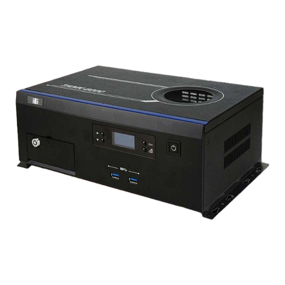
- Page 1 TANK-6000-C226 Em b e d d e d S ys te m MODEL: TANK-6000-C226 Em b e d d e d s ys te m s u p p o rts 22n m LGA1155 In te l® Xe o n ® E3 / Co re ™ i3 CP U, HDMI, VGA, Gb E, Two US B 2.0, Fo u r US B 3.0, Two COM a n d Ro HS Co m p lia n t Us e r Ma n u a l...
- Page 2 TANK-6000-C226 Em b e d d e d S ys te m Re vis io n Date Version Changes 14 March 2014 1.00 Initial release P a g e ii...
- Page 3 TANK-6000-C226 Em b e d d e d S ys te m Co p yrig h t COP YRIGHT NOTICE The information in this document is subject to change without prior notice in order to improve reliability, design and function and does not represent a commitment on the part of the manufacturer.
-
Page 4: Table Of Contents
TANK-6000-C226 Em b e d d e d S ys te m Ta b le o f Co n te n ts 1 INTRODUCTION ......................1 1.1 O ........................2 VERVIEW 1.2 M ....................2 ODEL ARIATIONS 1.3 F ........................3 EATURES 1.4 T .................. - Page 5 TANK-6000-C226 Em b e d d e d S ys te m 3.8.5 USB Device Connection ................... 25 3.8.6 VGA Monitor Connection ................26 4 SYSTEM MOTHERBOARD ..................28 4.1 M ..................29 OTHERBOARD AYOUT 4.2 I ..............30 NTERNAL ERIPHERAL ONNECTORS 4.2.1 12 V Power Connector (CN1) ................
- Page 6 TANK-6000-C226 Em b e d d e d S ys te m 5.1.4 Unable to Reboot after Configuration Changes ..........41 5.1.5 BIOS Menu Bar ....................41 5.2 M ........................42 5.3 A ....................... 44 DVANCED 5.3.1 ACPI Settings ....................45 5.3.2 RTC Wake Settings ...................
- Page 7 TANK-6000-C226 Em b e d d e d S ys te m A.2.2 Cleaning Tools ....................80 B BIOS MENU OPTIONS ..................... 81 C ONE KEY RECOVERY ..................... 84 C.1 O ..............85 ECOVERY NTRODUCTION C.1.1 System Requirement ..................86 C.1.2 Supported Operating System ................
- Page 8 TANK-6000-C226 Em b e d d e d S ys te m Lis t o f Fig u re s Figure 1-1: TANK-6000-C226 ......................2 Figure 1-2: TANK-6000-C226 Front Panel ..................5 Figure 1-3: TANK-6000-C226 Rear Panel ..................6 Figure 1-4: Physical Dimensions (mm) ..................7 Figure 3-1: HDD Cover Retention Screws ..................14 Figure 3-2: HDD Bracket Retention Screws ................15 Figure 3-3: Inserting the HDD ......................15...
- Page 9 TANK-6000-C226 Em b e d d e d S ys te m Figure C-8: Building the Recovery Partition ................95 Figure C-9: Press Any Key to Continue ..................95 Figure C-10: Press F3 to Boot into Recovery Mode ..............96 Figure C-11: Recovery Tool Menu ....................96 Figure C-12: About Symantec Ghost Window ................97 Figure C-13: Symantec Ghost Path ....................97 Figure C-14: Select a Local Source Drive ..................98...
- Page 10 TANK-6000-C226 Em b e d d e d S ys te m Lis t o f Ta b le s Table 1-1: Model Variations ......................2 Table 1-2: Technical Specifications ....................4 Table 2-1: Package List Contents ....................11 Table 4-1: Peripheral Interface Connectors ................30 Table 4-2: 12 V Power Connector (CN1) Pinouts ...............30 Table 4-3: Battery Connector (BAT1) Pinouts ................31 Table 4-4: BMC Debug Connector (J2_BMC) Pinouts ..............31...
-
Page 11: Introduction
TANK-6000-C226 Em b e d d e d S ys te m Ch a p te r In tro d u c tio n P a g e 1... -
Page 12: Overview
1.2 Mo d e l Va ria tio n s The model variations of the TANK-6000-C226 series are listed below. Models TANK-6000-C226i-E3/4G-R10 Intel® quad-core Xeon® E3-1225 v3 3.2GHz (TDP 84W) TANK-6000-C226i-i3/4G-R10 Intel® dual-core Core™ i3- 4330 3.5GHz (TDP 54W) -
Page 13: Features
TANK-6000-C226 Em b e d d e d S ys te m 1.3 Fe a tu re s The TANK-6000-C226 features are listed below: LGA1155 socket supports Intel® Xeon® E3 / Core™ i3 CPU (up to 95W CPU ) ... -
Page 14: Front Panel
TANK-6000-C226 Em b e d d e d S ys te m I/O in te rfa c e s 4 x USB 3.0 US B 2 x USB 2.0 1 x RJ-45 for Intel® i217 PHY with AMT 8.0 supported Eth e rn e t 3 x RJ-45 for Intel®... -
Page 15: Rear Panel
TANK-6000-C226 Em b e d d e d S ys te m 2 x HDD/SSD bay 1 x OLED display 1 x Power button 2 x USB 3.0 connectors Figure 1-2: TANK-6000-C226 Front Panel 1.6 Re a r P a n e l The rear panel of the TANK-6000-C226 has the following features (Figure 1-3): ... -
Page 16: Figure 1-3: Tank-6000-C226 Rear Panel
TANK-6000-C226 Em b e d d e d S ys te m Figure 1-3: TANK-6000-C226 Rear Panel P a g e 6... -
Page 17: Dimensions
TANK-6000-C226 Em b e d d e d S ys te m 1.7 Dim e n s io n s The physical dimensions are shown below: Figure 1-4: Physical Dimensions (mm) P a g e 7... -
Page 18: Unpacking
TANK-6000-C226 Em b e d d e d S ys te m Ch a p te r Un p a c kin g P a g e 8... -
Page 19: Anti - Static Precautions
TANK-6000-C226 Em b e d d e d S ys te m 2.1 An ti-s ta tic P re c a u tio n s WARNING: Failure to take ESD precautions during installation may result in permanent damage to the TANK-6000-C226 and severe injury to the user. -
Page 20: Unpacking Checklist
TANK-6000-C226 Em b e d d e d S ys te m 2.3 Un pa c kin g Ch e c klis t NOTE: If some of the components listed in the checklist below are missing, please do not proceed with the installation. Contact the IEI reseller or vendor you purchased the TANK-6000-C226 from or contact an IEI sales representative directly. -
Page 21: Table 2-1: Package List Contents
TANK-6000-C226 Em b e d d e d S ys te m Qu a n tity Ite m a n d P a rt Nu m b e r Im a g e Utility CD One Key Recovery CD Table 2-1: Package List Contents P a g e 11... -
Page 22: Installation
TANK-6000-C226 Em b e d d e d S ys te m Ch a p te r In s ta lla tio n P a g e 12... -
Page 23: Installation Precautions
TANK-6000-C226 Em b e d d e d S ys te m 3.1 In s ta lla tio n P re c a u tio n s During installation, be aware of the precautions below: Read the user manual: The user manual provides a complete description of the TANK-6000-C226, installation instructions and configuration options. -
Page 24: Hard Disk Drive (Hdd) Installation
TANK-6000-C226 Em b e d d e d S ys te m 3.3 Ha rd Dis k Drive (HDD) In s ta lla tio n 3.3.1 S e ria l ATA 2.0 Drive In s ta lla tio n To install the hard disk drive to the SATA 2.0 driver bay, please follow the steps below: Remove two retention screws from the HDD cover, as shown in F igure 3-1. -
Page 25: Figure 3-2: Hdd Bracket Retention Screws
TANK-6000-C226 Em b e d d e d S ys te m Figure 3-2: HDD Bracket Retention Screws S te p 4: Lift the HDD bracket out of the TANK-6000-C226 and slide the HDD to the HDD bracket ( F igure 3-3). 3 3 6 H Figure 3-3: Inserting the HDD Install the HDD bracket in the same position it was before and tighten the HDD... -
Page 26: Serial Ata 3.0 Drive Installation
TANK-6000-C226 Em b e d d e d S ys te m 3.3.2 S e ria l ATA 3.0 Drive In s ta lla tio n To install the hard disk drive to the SATA 3.0 driver bay, please follow the steps below: S te p 1: Unlock the HDD drive bay using the key. -
Page 27: Pci E Expansion Card Installation (Optional )
TANK-6000-C226 Em b e d d e d S ys te m Figure 3-6: Installing the HDD S te p 4: Install the HDD bracket in the same position it was before and tighten the HDD bracket retention screws. Lock the HDD drive bay using the key S te p 5: 3.4 P CIe Expa n s io n Ca rd In s ta lla tio n (Op tio n a l) To install a PCIe expansion card, please do the following. -
Page 28: Figure 3-8: Expansion Slot Retention Screw
TANK-6000-C226 Em b e d d e d S ys te m S te p 2: Remove the expansion slot cover. The expansion slot cover is secured to the system with a single retention screw. Remove the screw. Figure 3-8: Expansion Slot Retention Screw Insert the expansion card. -
Page 29: At/Atx Mode Selection
TANK-6000-C226 Em b e d d e d S ys te m 3.5 AT/ATX Mo d e S e le c tio n AT or ATX power mode can be used on the TANK-6000-C226. The selection is made through an AT/ATX switch located on the rear panel. To select AT mode or ATX mode, follow the steps below. -
Page 30: Reset The System
TANK-6000-C226 Em b e d d e d S ys te m in standby mode. Remote power control is perfect for advertising applications since the broadcasting time for each panel PC can be set individually and controlled remotely. Other possible application includes: ... -
Page 31: External Peripheral Interface Connectors
TANK-6000-C226 Em b e d d e d S ys te m S te p 3: Secure the brackets to the system by inserting two retention screws into each bracket as illustrated in F igure 3-12. 3 4 0 H Figure 3-12: Mounting Bracket Retention Screws Drill holes in the intended installation surface. -
Page 32: Audio Connection
TANK-6000-C226 Em b e d d e d S ys te m To install these devices, connect the corresponding cable connector from the actual device to the corresponding TANK-6000-C226 external peripheral interface connector making sure the pins are properly aligned. 3.8.1 Au d io Co n n e c tio n The audio jacks on the external audio connector enable the TANK-6000-C226 to be connected to a stereo sound setup. -
Page 33: Hdmi Device Connection
TANK-6000-C226 Em b e d d e d S ys te m 3.8.2 HDMI De vic e Co n n e c tio n The HDMI connector transmits a digital signal to compatible HDMI display devices such as a TV or computer screen. To connect the HDMI cable to the TANK-6000-C226, follow the steps below. -
Page 34: Serial Port Connection
TANK-6000-C226 Em b e d d e d S ys te m Locate the RJ-45 connectors. The location of the LAN connector is shown in S te p 1: Chapter 1. S te p 2: Align the connectors. Align the RJ-45 connector on the LAN cable with one of the RJ-45 connectors on the TANK-6000-C226. -
Page 35: Usb Device Connection
TANK-6000-C226 Em b e d d e d S ys te m Figure 3-16: DB-9 Serial Port Connector Secure the connector. Secure the serial device connector to the external S te p 3: interface by tightening the two retention screws on either side of the connector. Step 0: 3.8.5 US B De vic e Co n n e c tio n NOTE:... -
Page 36: Vga Monitor Connection
TANK-6000-C226 Em b e d d e d S ys te m Align the connectors. Align the USB device connector with one of the S te p 2: connectors on the external peripheral interface. See Figure 3-18. Figure 3-17: USB Device Connection S te p 3: Insert the device connector. -
Page 37: Figure 3-19: Vga Connector
TANK-6000-C226 Em b e d d e d S ys te m Insert the VGA connector. Once the connectors are properly aligned with the S te p 3: insert the male connector from the VGA screen into the female connector on the TANK-6000-C226. -
Page 38: System Motherboard
TANK-6000-C226 Em b e d d e d S ys te m Ch a p te r S ys te m Mo th e rb o a rd P a g e 28... -
Page 39: Motherboard Layout
TANK-6000-C226 Em b e d d e d S ys te m 4.1 Mo th e rb o a rd La yo u t The TANK-6000-C226 embedded system motherboard comes with a number of peripheral interface connectors and configuration jumpers. The connector locations are shown in Figure 6-1. -
Page 40: Internal Peripheral Connectors
TANK-6000-C226 Em b e d d e d S ys te m 4.2 In te rn a l P e rip h e ra l Co n n e c to rs Internal peripheral connectors are found on the motherboard and are only accessible when the motherboard is outside of the chassis. -
Page 41: Battery Connector (Bat1)
TANK-6000-C226 Em b e d d e d S ys te m 4.2.2 Ba tte ry Co n n e c to r (BAT1) PIN NO. DESCRIPTION VBATT Table 4-3: Battery Connector (BAT1) Pinouts 4.2.3 BMC De b u g Co n n e c to r (J 2_BMC) PIN NO. -
Page 42: Fan Connectors (Cpu_Fan1, Sys_Fan2)
TANK-6000-C226 Em b e d d e d S ys te m 4.2.5 Fa n Co n n e c to rs (CP U_FAN1, S YS _FAN2) PIN NO. DESCRIPTION +12V FANIO Table 4-6: Fan Connectors (CPU_FAN1, SYS_FAN2) Pinouts 4.2.6 Fla s h BIOS ROM Co n n e c to r (J S P I1) PIN NO. -
Page 43: Flash Bmc Rom Connector (Spi1)
TANK-6000-C226 Em b e d d e d S ys te m 4.2.8 Fla s h BMC ROM Co n n e c to r (S P I1) PIN NO. DESCRIPTION SPI_VCC FLA_CS0_R FLA_D2_R FLA_D0_R FLA_D1_R Table 4-9: Flash BMC ROM Connector (SPI1) Pinouts 4.2.9 OLED Co n n e c to r (OLED1) PIN NO. -
Page 44: Serial Ata 3.0 Connectors (Sata1)
TANK-6000-C226 Em b e d d e d S ys te m 4.2.11 S e ria l ATA 3.0 c o n n e c to rs (S ATA1) PIN NO. DESCRIPTION PIN NO. DESCRIPTION SATA_TX2+_C SATA_TX2-_C SATA_RX2-_C SATA_RX2+_C +3.3V +3.3V +12V +3.3V... -
Page 45: Audio Input & Output Connectors (Mic1, Audio1)
TANK-6000-C226 Em b e d d e d S ys te m Co n n e c to r Typ e La b e l USB 2.0 connector Dual USB 2.0 port USB_CON3 VGA connector 15-pin female VGA1 Table 4-13: Rear Panel Connectors 4.3.1 Au d io In p u t &... -
Page 46: Ethernet Connectors (Lan3, Lan4)
TANK-6000-C226 Em b e d d e d S ys te m 4.3.4 Eth e rn e t Co n n e c to rs (LAN3, LAN4) PIN NO. DESCRIPTION PIN NO. DESCRIPTION LAN1_MDI0P LAN1_MDI2P LAN1_MDI0N LAN1_MDI2N LAN1_MDI1P LAN1_MDI3P LAN1_MDI1N LAN1_MDI3N Table 4-17: Ethernet Connector (LAN3, LAN4) Pinouts 4.3.5 Exte rn a l Fib e r Co n n e c to rs (S FP LAN1, S FP LAN 2) -
Page 47: Serial Port (Com1_2)
TANK-6000-C226 Em b e d d e d S ys te m HDMI_GND HDMI_DATA0# HDMI_GND HDMI_CLK HDMI_GND HDMI_GND HDMI_CLK# Table 4-19: HDMI Connector (HDMI1) Pinouts 4.3.7 RS -232 S e ria l P o rt (COM1_2) PIN NO. DESCRIPTION PIN NO. DESCRIPTION -NDCD1 -NDCD2... -
Page 48: Usb 2.0 Connectors (Usb_Con3)
TANK-6000-C226 Em b e d d e d S ys te m USB_DATA- USB_DATA- USB_DATA+ USB_ DATA+ USB3_RX- USB3_RX- USB3_RX+ USB3_ RX+ USB3_TX- USB3_TX- USB3_TX+ USB3_TX+ Table 4-22: USB 3.0 Connector (USB_CON4) Pinouts 4.3.10 US B 2.0 Co n n e c to rs (US B_CON3) PIN NO. -
Page 49: Bios
TANK-6000-C226 Em b e d d e d S ys te m Ch a p te r BIOS P a g e 39... -
Page 50: Introduction
TANK-6000-C226 Em b e d d e d S ys te m 5.1 In tro d u c tio n The BIOS is programmed onto the BIOS chip. The BIOS setup program allows changes to certain system settings. This chapter outlines the options that can be changed. NOTE: Some of the BIOS options may vary throughout the life cycle of the product and are subject to change without prior notice. -
Page 51: Getting Help
TANK-6000-C226 Em b e d d e d S ys te m Ke y Fu n c tio n Decrease the numeric value or make changes Esc key Main Menu – Quit and not save changes into CMOS Status Page Setup Menu and Option Page Setup Menu -- Exit current page and return to Main Menu F1 key General help, only for Status Page Setup Menu and Option... -
Page 52: Main
TANK-6000-C226 Em b e d d e d S ys te m The following sections completely describe the configuration options found in the menu items at the top of the BIOS screen and listed above. 5.2 Ma in The Main BIOS menu (BIOS Menu 1) appears when the BIOS Setup program is entered. The Main menu gives an overview of the basic system information. - Page 53 TANK-6000-C226 Em b e d d e d S ys te m Aptio Setup Utility – Copyright (C) 2012 American Megatrends, Inc. Main Advanced Chipset Boot Security Save & Exit BIOS Information Set the Date. Use Tab to BIOS Vendor American Megatrends switch between Data Core Version...
-
Page 54: Advanced
TANK-6000-C226 Em b e d d e d S ys te m BIOS Information Processor Information Memory Information PCH Information SPI Clock Frequency The Main menu has two user configurable fields: S ys te m Da te [xx/xx/xx] Use the System Date option to set the system date. -
Page 55: Acpi Settings
TANK-6000-C226 Em b e d d e d S ys te m Aptio Setup Utility – Copyright (C) 2012 American Megatrends, Inc. Main Advanced Chipset Boot Security Save & Exit > ACPI Settings System ACPI Parameters > RTC Wake Settings >... -
Page 56: Rtc Wake Settings
TANK-6000-C226 Em b e d d e d S ys te m ACP I S le e p Sta te [S 1 o n ly (CP U Sto p Clo c k)] Use the ACPI Sleep State option to specify the sleep state the system enters when it is not being used. -
Page 57: Cpu Information
TANK-6000-C226 Em b e d d e d S ys te m Wa ke S ys te m with Fixe d Tim e [Dis a b le d ] Use the Wake System with Fixed Time option to specify the time the system should be roused from a suspended state. - Page 58 TANK-6000-C226 Em b e d d e d S ys te m Aptio Setup Utility – Copyright (C) 2012 American Megatrends, Inc. Advanced CPU Information Enable for Windows XP and Linux (OS optimized for Intel® COR(TM) i7-4770S CPU @ 3.10GHz Hyper-Threading CPU Signature 306c3...
- Page 59 TANK-6000-C226 Em b e d d e d S ys te m Intel SMX Technology: Indicates if Intel SMX Technology is supported by the CPU. EIST Technology: Indicates if Enhanced Intel SpeedStep® Techonology is supported by the CPU. ...
-
Page 60: Sata Configuration
TANK-6000-C226 Em b e d d e d S ys te m EIS T [En a b le d ] Use the EIST option to enable or disable Enhanced Intel SpeedStep® Techonology (EIST). Disables Enhanced Intel SpeedStep® Disabled Techonology. -
Page 61: Intel(R) Rapid Start Technology
TANK-6000-C226 Em b e d d e d S ys te m Disables the on-board SATA controller. Disabled S ATA Mo d e S e le c tio n [IDE Mo d e ] Use the SATA Mode Selection option to configure SATA devices as normal IDE devices. ... -
Page 62: Amt Configuration
TANK-6000-C226 Em b e d d e d S ys te m Intel® Rapid Start Technology is enabled Enabled 5.3.6 AMT Co n fig u ra tio n The AMT Configuration submenu (BIOS Menu 8) allows Intel® Active Management Technology (AMT) options to be configured. -
Page 63: Usb Configuration
TANK-6000-C226 Em b e d d e d S ys te m Disable ME unconfigure Disabled EFAULT Enabled Enable ME unconfigure 5.3.7 US B Co n fig u ra tio n Use the USB Configuration menu (BIOS Menu 9) to read USB configuration information and configure the USB settings. -
Page 64: F81866 Super Io Configuration
TANK-6000-C226 Em b e d d e d S ys te m keyboard can control the system even when there is no USB driver loaded onto the system. Enabled Legacy USB support enabled EFAULT Disabled Legacy USB support disabled ... -
Page 65: Serial Port N Configuration
TANK-6000-C226 Em b e d d e d S ys te m 5.3.8.1 S e ria l P o rt n Co n fig u ra tio n Use the Serial Port n Configuration menu (BIOS Menu 11) to configure the serial port n. Aptio Setup Utility –... - Page 66 TANK-6000-C226 Em b e d d e d S ys te m Serial Port I/O port address is 3F8h and the interrupt IO=3F8h; IRQ=3, 4 address is IRQ3,4 IO=2C0h; Serial Port I/O port address is 2C0h and the interrupt address is IRQ3, 4 IRQ=3, 4 ...
-
Page 67: Iwdd H/W Monitor
TANK-6000-C226 Em b e d d e d S ys te m 5.3.9 iWDD H/W Mo n ito r The iWDD H/W Monitor menu (BIOS Menu 12) contains the fan configuration submenus and displays operating temperature, fan speeds and system voltages. Aptio Setup Utility –... -
Page 68: Smart Fan Mode Configuration
TANK-6000-C226 Em b e d d e d S ys te m +3.3V +3.3VSB 5.3.9.1 S m a rt Fa n Mo d e Co nfig u ra tio n Use the Smart Fan Mode Configuration submenu (BIOS Menu 13) to configure smart fan temperature and speed settings. -
Page 69: Serial Port Console Redirection
TANK-6000-C226 Em b e d d e d S ys te m Fa n s ta rt P WM Use the + or – key to change the Fan start PWM value. Enter a decimal number between 1 and 128. ... - Page 70 TANK-6000-C226 Em b e d d e d S ys te m Enabled the console redirection function Enabled The following options are available in the Console Redirection Settings submenu when the Console Redirection option is enabled. Te rm in a l Typ e [ANS I] Use the Terminal Type option to specify the remote terminal type.
- Page 71 TANK-6000-C226 Em b e d d e d S ys te m No parity bit is sent with the data bits. None EFAULT Even The parity bit is 0 if the number of ones in the data bits is even. ...
-
Page 72: Iei Feature
TANK-6000-C226 Em b e d d e d S ys te m 5.3.11 iEi Fe a tu re Use the iEi Feature menu (BIOS Menu 15) to configure IEI One Key Recovery function. Aptio Setup Utility – Copyright (C) 2012 American Megatrends, Inc. Advanced iEi Feature Auto Recovery Function... -
Page 73: Chipset
TANK-6000-C226 Em b e d d e d S ys te m 5.4 Ch ips e t Use the Chipset menu (BIOS Menu 16) to access the PCH-IO and System Agent (SA) Subsystem configuration menus. WARNING! Setting the wrong values for the Chipset BIOS selections in the Chipset BIOS menu may cause the system to malfunction. -
Page 74: Pch-Io Configuration
TANK-6000-C226 Em b e d d e d S ys te m 5.4.1 P CH-IO Co n fig u ra tio n Use the PCH-IO Configuration menu (BIOS Menu 17) to configure the PCH chipset. Aptio Setup Utility – Copyright (C) 2012 American Megatrends, Inc. Chipset Auto Power Button Status [Disabled (ATX)]... -
Page 75: Pch Azalia Configuration
TANK-6000-C226 Em b e d d e d S ys te m Power Saving Function support enabled Enabled US B P o we r S W1 [+5V DUAL] Use the USB Power SW1 BIOS option to configure the USB power source for the corresponding USB connector. -
Page 76: System Agent (Sa) Configuration
TANK-6000-C226 Em b e d d e d S ys te m The onboard High Definition Audio controller is detected Enabled EFAULT automatically and enabled 5.4.2 S ys te m Ag e n t (S A) Co n fig u ra tio n Use the System Agent (SA) Configuration menu (BIOS Menu 19) to configure the video device connected to the system. -
Page 77: Graphics Configuration
TANK-6000-C226 Em b e d d e d S ys te m 5.4.2.1 Gra p h ic s Co n fig u ra tio n Use the Graphics Configuration submenu (BIOS Menu 20) to configure the graphics settings. Aptio Setup Utility – Copyright (C) 2012 American Megatrends, Inc. Chipset Graphics Configuration Select which of... - Page 78 TANK-6000-C226 Em b e d d e d S ys te m 64 MB of memory used by internal graphics device 128M 128 MB of memory used by internal graphics device 256M 256 MB of memory used by internal graphics EFAULT device ...
- Page 79 TANK-6000-C226 Em b e d d e d S ys te m Aptio Setup Utility – Copyright (C) 2012 American Megatrends, Inc. Chipset LCD Control Select the Video Device which will be activated Primary IGFX Boot Display [VBIOS Default] during POST. This has no effect if external graphics present.
-
Page 80: Nb Pcie Configuration
TANK-6000-C226 Em b e d d e d S ys te m 5.4.2.2 NB P CIe Co n fig u ra tio n Use the NB PCIe Configuration submenu (BIOS Menu 22) to configure the northbridge PCIe settings. Aptio Setup Utility – Copyright (C) 2012 American Megatrends, Inc. Chipset NB PCIe Configuration Configure PEG0 B0:D1:F0... -
Page 81: Memory Configuration
TANK-6000-C226 Em b e d d e d S ys te m De te c t No n -Co m p lia n c e [En a b le d ] Use the Detect Non-Compliance option to detect non-compliance PCIe device in PEG. ... -
Page 82: Boot
TANK-6000-C226 Em b e d d e d S ys te m 5.5 Bo o t Use the Boot menu (BIOS Menu 24) to configure system boot options. Aptio Setup Utility – Copyright (C) 2012 American Megatrends, Inc. Main Advanced Chipset Boot Security... - Page 83 TANK-6000-C226 Em b e d d e d S ys te m Qu ie t Bo o t [En a b le d ] Use the Quiet Boot BIOS option to select the screen display when the system boots. ...
-
Page 84: Security
TANK-6000-C226 Em b e d d e d S ys te m 5.6 S e c u rity Use the Security menu (BIOS Menu 25) to set system and user passwords. Aptio Setup Utility – Copyright (C) 2012 American Megatrends, Inc. Main Advanced Chipset... - Page 85 TANK-6000-C226 Em b e d d e d S ys te m Aptio Setup Utility – Copyright (C) 2012 American Megatrends, Inc. Main Advanced Chipset Boot Security Save & Exit Save Changes and Reset Exit the system after Discard Changes and Reset saving the changes.
-
Page 86: A Safety Precautions
TANK-6000-C226 Em b e d d e d S ys te m Appendix S a fe ty P re c a u tio n s P a g e 76... -
Page 87: Safety Precautions
TANK-6000-C226 Em b e d d e d S ys te m WARNING: The precautions outlined in this chapter should be strictly followed. Failure to follow these precautions may result in permanent damage to the TANK-6000-C226. A.1 S a fe ty P re c a u tio n s Please follow the safety precautions outlined in the sections that follow: A.1.1 Ge n e ra l S a fe ty P re c a u tio n s Please ensure the following safety precautions are adhered to at all times. -
Page 88: Anti-Static Precautions
TANK-6000-C226 Em b e d d e d S ys te m A.1.2 An ti-s ta tic P re c a u tio n s WARNING: Failure to take ESD precautions during the installation of the TANK-6000-C226 result permanent damage TANK-6000-C226 and severe injury to the user. -
Page 89: Product Disposal
TANK-6000-C226 Em b e d d e d S ys te m A.1.3 P ro d u c t Dis p o s a l CAUTION: Risk of explosion if battery is replaced by and incorrect type. Only certified engineers should replace the on-board battery. Dispose of used batteries according to instructions and local regulations. -
Page 90: Cleaning Tools
TANK-6000-C226 Em b e d d e d S ys te m The interior of the TANK-6000-C226X does not require cleaning. Keep fluids away from the TANK-6000-C226 interior. Be cautious of all small removable components when vacuuming the TANK-6000-C226. -
Page 91: B Bios Menu Options
TANK-6000-C226 Em b e d d e d S ys te m Appendix BIOS Me n u Op tio n s P a g e 81... - Page 92 TANK-6000-C226 Em b e d d e d S ys te m System Date [xx/xx/xx] ......................44 System Time [xx:xx:xx] .......................44 ACPI Sleep State [S1 only (CPU Stop Clock)] ..............46 Wake System with Fixed Time [Disabled] .................47 ...
- Page 93 TANK-6000-C226 Em b e d d e d S ys te m Azalia [Enabled] ........................65 VT-d [Enabled] ........................66 Primary Display [Auto] ......................67 DVMT Pre-Allocated [256M] ....................67 DVMT Total Gfx Mem [Max] ....................68 Primary IGFX Boot Display [VBIOS Default] ..............69 ...
-
Page 94: C One Key Recovery
TANK-6000-C226 Em b e d d e d S ys te m Ap p e n d ix On e Ke y Re c o ve ry P a g e 84... -
Page 95: One Key Recovery Introduction
TANK-6000-C226 Em b e d d e d S ys te m C.1 On e Ke y Re c o ve ry In tro d u c tio n The IEI one key recovery is an easy-to-use front end for the Norton Ghost system backup and recovery tool. -
Page 96: System Requirement
TANK-6000-C226 Em b e d d e d S ys te m After completing the five initial setup procedures as described above, users can access the recovery tool by pressing <F3> while booting up the system. The detailed information of each function is described in Section C.5. NOTE: The initial setup procedures for Linux system are described in Section C.3. -
Page 97: Supported Operating System
TANK-6000-C226 Em b e d d e d S ys te m partitions. Please take the following table as a reference when calculating the size of the partition. OS Image after Ghost Compression Ratio Windows® 7 7 GB 5 GB Windows®... -
Page 98: Setup Procedure For Windows
TANK-6000-C226 Em b e d d e d S ys te m Ubuntu 8.10 (Intrepid) Ubuntu 7.10 (Gutsy) Ubuntu 6.10 (Edgy) Debian 5.0 (Lenny) Debian 4.0 (Etch) SuSe 11.2 SuSe 10.3 NOTE: Installing unsupported OS versions may cause the recovery tool to fail. C.2 S e tu p P ro c e d u re fo r Win d ows Prior to using the recovery tool to backup or restore, a few setup procedures are required. -
Page 99: Hardware And Bios Setup
TANK-6000-C226 Em b e d d e d S ys te m C.2.1 Ha rdwa re a n d BIOS S e tu p Make sure the system is powered off and unplugged. S te p 1: Install a hard drive or SSD in the system. An unformatted and unpartitioned disk S te p 2: is recommended. -
Page 100: Figure C-2: Launching The Recovery Tool
TANK-6000-C226 Em b e d d e d S ys te m Figure C-2: Launching the Recovery Tool S te p 3: The recovery tool setup menu is shown as below. Figure C-3: Recovery Tool Setup Menu S te p 4: Press <6>... -
Page 101: Figure C-4: Command Prompt
TANK-6000-C226 Em b e d d e d S ys te m Figure C-4: Command Prompt S te p 5: The command prompt window appears. Type the following commands (marked in red) to create two partitions. One is for the OS installation; the other is for saving recovery files and images which will be an invisible partition. -
Page 102: Figure C-5: Partition Creation Commands
TANK-6000-C226 Em b e d d e d S ys te m Figure C-5: Partition Creation Commands P a g e 92... -
Page 103: Install Operating System, Drivers And Applications
TANK-6000-C226 Em b e d d e d S ys te m NOTE: Use the following commands to check if the partitions were created successfully. S te p 6: Press any key to exit the recovery tool and automatically reboot the system. Please continue to the following procedure: Build the Recovery Partition.S t e p 0 : C.2.3 In s ta ll Op e ra tin g S ys te m , Drive rs a n d Ap p lic a tio n s... -
Page 104: Building The Recovery Partition
TANK-6000-C226 Em b e d d e d S ys te m C.2.4 Bu ild in g th e Re c o ve ry P a rtitio n Put the recover CD in the optical drive. S te p 1: Start the system. -
Page 105: Figure C-8: Building The Recovery Partition
TANK-6000-C226 Em b e d d e d S ys te m S te p 5: The Symantec Ghost window appears and starts configuring the system to build a recovery partition. In this process the partition created for recovery files in Section C.2.2 is hidden and the recovery tool is saved in this partition. -
Page 106: Create Factory Default Image
TANK-6000-C226 Em b e d d e d S ys te m C.2.5 Cre a te Fa c to ry De fa u lt Im a g e NOTE: Before creating the factory default image, please configure the system to a factory default environment, including driver and application installations. -
Page 107: Figure C-12: About Symantec Ghost Window
TANK-6000-C226 Em b e d d e d S ys te m Figure C-12: About Symantec Ghost Window Use mouse to navigate to the option shown below (Figure C-13). S te p 4: Figure C-13: Symantec Ghost Path S te p 5: Select the local source drive (Drive 1) as shown in Figure C-14. -
Page 108: Figure C-14: Select A Local Source Drive
TANK-6000-C226 Em b e d d e d S ys te m Figure C-14: Select a Local Source Drive S te p 6: Select a source partition (Part 1) from basic drive as shown in Figure C-15. Then click OK. Figure C-15: Select a Source Partition from Basic Drive Select 1.2: [Recovery] NTFS drive and enter a file name called S te p 7:... -
Page 109: Figure C-16: File Name To Copy Image To
TANK-6000-C226 Em b e d d e d S ys te m Figure C-16: File Name to Copy Image to When the Compress Image screen in Figure C-17 prompts, click High to make S te p 8: the image file smaller. Figure C-17: Compress Image P a g e 99... -
Page 110: Figure C-18: Image Creation Confirmation
TANK-6000-C226 Em b e d d e d S ys te m The Proceed with partition image creation window appears, click Yes to S te p 9: continue. Figure C-18: Image Creation Confirmation The Symantec Ghost starts to create the factory default image (Figure C-19). S te p 10: Figure C-19: Image Creation Complete When the image creation completes, a screen prompts as shown in Figure C-20. -
Page 111: Auto Recovery Setup Procedure
TANK-6000-C226 Em b e d d e d S ys te m S te p 12: The recovery tool main menu window is shown as below. Press any key to reboot the system. S t e p 0 : Figure C-21: Press Any Key to Continue C.3 Au to Re c o ve ry S e tu p P ro c e d u re The auto recovery function allows a system to automatically restore from the factory default image after encountering a Blue Screen of Death (BSoD) or a hang for around 10... -
Page 112: Figure C-22: Auto Recovery Utility
TANK-6000-C226 Em b e d d e d S ys te m Figure C-22: Auto Recovery Utility Reboot the system from the recovery CD. When prompted, press any key to S te p 3: boot from the recovery CD. It will take a while to launch the recovery tool. Please be patient! Figure C-23: Launching the Recovery Tool When the recovery tool setup menu appears, press <4>... -
Page 113: Figure C-25: Building The Auto Recovery Partition
TANK-6000-C226 Em b e d d e d S ys te m S te p 5: The Symantec Ghost window appears and starts configuring the system to build an auto recovery partition. In this process the partition created for recovery files in Section C.2.2 is hidden and the auto recovery tool is saved in this partition. -
Page 114: Figure C-27: Image Creation Complete
TANK-6000-C226 Em b e d d e d S ys te m The Symantec Ghost starts to create the factory default image (Figure C-27). S te p 7: Figure C-27: Image Creation Complete S te p 8: After completing the system configuration, press any key in the following window to restart the system. -
Page 115: Setup Procedure For Linux
TANK-6000-C226 Em b e d d e d S ys te m Aptio Setup Utility – Copyright (C) 2011 American Megatrends, Inc. Advanced iEi Feature Auto Recovery Function Reboot and recover Auto Recovery Function [Disabled] system automatically within 10 min, when OS crashes. -
Page 116: Figure C-29: Partitions For Linux
TANK-6000-C226 Em b e d d e d S ys te m Hardware and BIOS setup. Refer to Section C.2.1. S te p 1: Install Linux operating system. Make sure to install GRUB (v0.97 or earlier) S te p 2: MBR type and Ext3 partition type. -
Page 117: Figure C-30: Manual Recovery Environment For Linux
TANK-6000-C226 Em b e d d e d S ys te m DISKPART>sel disk 0 DISKPART>create part pri size= DISKPART>assign letter=N DISKPART>exit system32>format N: /fs:ntfs /q /v:Recovery /y system32>exit S te p 4: Build the recovery partition. Press any key to boot from the recovery CD. It will take a while to launch the recovery tool. -
Page 118: Figure C-31: Access Menu.lst In Linux (Text Mode)
TANK-6000-C226 Em b e d d e d S ys te m Figure C-31: Access menu.lst in Linux (Text Mode) Modify the menu.lst as shown below. S te p 6: The recovery tool menu appears. (Figure C-32) S te p 7: Figure C-32: Recovery Tool Menu Create a factory default image. -
Page 119: Recovery Tool Functions
TANK-6000-C226 Em b e d d e d S ys te m C.5 Re c o ve ry To o l Fu n c tio n s After completing the initial setup procedures as described above, users can access the recovery tool by pressing <F3>... -
Page 120: Factory Restore
TANK-6000-C226 Em b e d d e d S ys te m WARNING: All data in the system will be deleted during the system recovery. Please backup the system files before restoring the system (either Factory Restore or Restore Backup). C.5.1 Fa c to ry Re s to re To restore the factory default image, please follow the steps below. -
Page 121: Backup System
TANK-6000-C226 Em b e d d e d S ys te m Figure C-35: Recovery Complete Window C.5.2 Ba c ku p S ys te m To backup the system, please follow the steps below. Type <2> and press <Enter> in the main menu. S te p 1: The Symantec Ghost window appears and starts to backup the system. -
Page 122: Restore Your Last Backup
TANK-6000-C226 Em b e d d e d S ys te m Figure C-37: System Backup Complete Window C.5.3 Re s to re Yo u r La s t Ba c ku p To restore the last system backup, please follow the steps below. Type <3>... -
Page 123: Manual
TANK-6000-C226 Em b e d d e d S ys te m Figure C-39: Restore System Backup Complete Window C.5.4 Ma n u a l To restore the last system backup, please follow the steps below. Type <4> and press <Enter> in the main menu. S te p 1: The Symantec Ghost window appears. -
Page 124: Restore Systems From A Linux Server Through Lan
TANK-6000-C226 Em b e d d e d S ys te m C.6 Re s to re S ys te m s fro m a Lin u x S e rve r thro u g h LAN The One Key Recovery allows a client system to automatically restore to a factory default image saved in a Linux system (the server) through LAN connectivity after encountering a Blue Screen of Death (BSoD) or a hang for around 10 minutes. -
Page 125: Configure Dhcp Server Settings
TANK-6000-C226 Em b e d d e d S ys te m C.6.1 Co n fig u re DHCP S e rve r S e ttin g s Install the DHCP S te p 1: #yum install dhcp (CentOS, commands marked in red) #apt-get install dhcp3-server (Debian, commands marked in blue) Confirm the operating system default settings: dhcpd.conf. -
Page 126: Configure Tftp Settings
TANK-6000-C226 Em b e d d e d S ys te m filename “pxelinux.0”; C.6.2 Co n fig u re TFTP S e ttin g s S te p 1: Install the tftp, httpd and syslinux. #yum install tftp-server httpd syslinux (CentOS) #apt-get install tftpd-hpa xinetd syslinux (Debian) -
Page 127: Configure One Key Recovery Server Settings
TANK-6000-C226 Em b e d d e d S ys te m Debian Replace the TFTP settings from “inetd” to “xinetd” and annotate the “inetd” by adding “#”. #vi /etc/inetd.conf Modify: #tftp dgram udp wait root /usr/sbin..(as shown below) #vi /etc/xinetd.d/tftp C.6.3 Co n fig u re On e Ke y Re c o ve ry S e rve r S e ttin g s Copy the Utility/RECOVERYR10.TAR.BZ2 package from the One Key... -
Page 128: Start The Dhcp, Tftp And Http
TANK-6000-C226 Em b e d d e d S ys te m C.6.4 Sta rt th e DHCP, TFTP a n d HTTP Start the DHCP, TFTP and HTTP. For example: CentOS #service xinetd restart #service httpd restart #service dhcpd restart Debian #/etc/init.d/xinetd reload #/etc/init.d/xinetd restart... -
Page 129: Setup A Client System For Auto Recovery
TANK-6000-C226 Em b e d d e d S ys te m Modify: [image] comment = One Key Recovery path = /share/image browseable = yes writable = yes public = yes create mask = 0644 directory mask = 0755 S te p 4: Edit “/etc/samba/smb.conf”... - Page 130 TANK-6000-C226 Em b e d d e d S ys te m Continue to configure the Boot Option Priorities BIOS option of the client S te p 2: system: Boot Option #1 remain the default setting to boot from the original OS. Boot Option #2 ...
- Page 131 TANK-6000-C226 Em b e d d e d S ys te m NOTE: A firewall or a SELinux is not in use in the whole setup process. If there is a firewall or a SELinux protecting the system, modify the configuration information to accommodate them.
-
Page 132: Other Information
TANK-6000-C226 Em b e d d e d S ys te m C.7 Oth e r In fo rm a tio n C.7.1 Us in g AHCI Mo d e o r ALi M5283 / VIA VT6421A Co n tro lle r When the system uses AHCI mode or some specific SATA controllers such as ALi M5283 or VIA VT6421A, the SATA RAID/AHCI driver must be installed before using one key recovery. - Page 133 TANK-6000-C226 Em b e d d e d S ys te m When the following window appears, press <S> to select “Specify Additional S te p 5: Device”. In the following window, select a SATA controller mode used in the system. Then S te p 6: press <Enter>.
-
Page 134: System Memory Requirement
TANK-6000-C226 Em b e d d e d S ys te m S te p 7: After pressing <Enter>, the system will get into the recovery tool setup menu. Continue to follow the setup procedure from Step 4 in Section C.2.2 Create Partitions to finish the whole setup process. -
Page 135: D Hazardous Materials Disclosure
TANK-6000-C226 Em b e d d e d S ys te m Ap p e n d ix Ha za rd o u s Ma te ria ls Dis c lo s u re P a g e 125... -
Page 136: Hazardous Materials Disclosure Table For Ipb Products Certified As R Ohs Compliant Under 2002/95/Ec Without Mercury
TANK-6000-C226 Em b e d d e d S ys te m D.1 Ha za rd o u s Ma te ria ls Dis c lo s u re Ta ble for IP B P ro d u c ts Ce rtifie d a s Ro HS Co m p lia n t Un d e r 2002/95/EC With o u t Me rc u ry The details provided in this appendix are to ensure that the product is compliant with the... - Page 137 TANK-6000-C226 Em b e d d e d S ys te m P a rt Na m e To xic o r Ha za rd o u s S u b s ta n c e s a n d Ele m e n ts Le a d Me rc u ry Ca d m iu m...
- Page 138 TANK-6000-C226 Em b e d d e d S ys te m 此附件旨在确保本产品符合中国 RoHS 标准。以下表格标示此产品中某有毒物质的含量符 合中国 RoHS 标准规定的限量要求。 本产品上会附有”环境友好使用期限”的标签,此期限是估算这些物质”不会有泄漏或突变”的 年限。本 产品可能包含有较短的环境友好使用期限的可替换元件,像是电池或灯管,这些元 件将会单独标示出来。 部件名称 有毒有害物质或元素 铅 汞 镉 六价铬 多溴联苯 多溴二苯 醚 (P b ) (Hg ) (Cd ) (CR(VI)) (P BB) (P BDE) 壳体...
Need help?
Do you have a question about the TANK-6000-C226i-E3/4G-R10 and is the answer not in the manual?
Questions and answers