Table of Contents
Advertisement
Quick Links
Advertisement
Table of Contents

Subscribe to Our Youtube Channel
Related Manuals for IEI Technology TANK -870-Q170 S eries


Summary of Contents for IEI Technology TANK -870-Q170 S eries
- Page 1 TANK -870-Q170 E mbedded S ys tem MODE L : TA NK -870-Q170 S eries E mbedded S ys tem with 6th/7th G eneration Intel® C ore™ proc es s or, 4G B DDR 4 pre-ins talled memory, V G A/HDMI+DP /iDP, Two G igabit E thernet, R S -232/422/485, R oHS C ompliant Us er Manual...
- Page 2 TANK -870-Q170 E mbedded S ys tem R evis ion Date Version Changes 13 July 2018 1.10 Update the pin define in the followings: Section 4.3.3: Ethernet and USB 2.0 Connectors (LAN1_USB1) Section 4.3.4: Ethernet and USB 2.0 Connectors (LAN2_USB2) Section 4.3.10: USB 3.0 Connectors (USB3_CN1) Section 4.3.11: USB 3.0 Connectors (USB3_CN2) 13 July 2018...
- Page 3 TANK -870-Q170 E mbedded S ys tem C opyright C OP Y R IG HT NOT IC E The information in this document is subject to change without prior notice in order to improve reliability, design and function and does not represent a commitment on the part of the manufacturer.
- Page 4 TANK -870-Q170 E mbedded S ys tem Manual C onventions WAR NING Warnings appear where overlooked details may cause damage to the equipment or result in personal injury. Warnings should be taken seriously. C AUT ION Cautionary messages should be heeded to help reduce the chance of losing data or damaging the product.
-
Page 5: Table Of Contents
TANK -870-Q170 E mbedded S ys tem Table of C ontents 1 INTRODUCTION ......................1 1.1 O ........................2 VERVIEW 1.2 M ..................... 3 ODEL ARIATIONS 1.3 F ........................3 EATURES 1.4 T ..................4 ECHNICAL PECIFICATIONS 1.5 F ......................7 RONT ANEL 1.5.1 TANK-870-Q170-2 slot Front Panel .............. - Page 6 TANK -870-Q170 E mbedded S ys tem 3.5.5 HDMI/DP Connector ..................35 3.5.6 LAN Connectors ....................35 3.5.7 Power Input, 3-pin Terminal Block ..............37 3.5.8 Power Input, 4-pin DIN Connector ..............37 3.5.9 RJ-45 RS-232 Serial Ports ................37 3.5.10 DB-9 RS-232/422/485 Serial Port Connectors ..........
- Page 7 TANK -870-Q170 E mbedded S ys tem 4.3.3 Ethernet and USB 2.0 Connectors (LAN1_USB1) ........... 56 4.3.4 Ethernet and USB 2.0 Connectors (LAN2_USB2) ........... 57 4.3.5 Power Connector (PWR1) ................57 4.3.6 Power Connector (PWR2) ................58 4.3.7 RS-232 Serial Port Connector (COM1_2) ............58 4.3.8 RS-232 Serial Port Connectors (COM3_4) .............
- Page 8 TANK -870-Q170 E mbedded S ys tem 5.4.1 System Agent (SA) Configuration ..............90 5.4.1.1 Graphics Configuration ................91 5.4.1.2 PEG Port Configuration ................93 5.4.1.3 Memory Configuration ................94 5.4.2 PCH-IO Configuration ..................95 5.4.2.1 PCI Express Configuration ............... 96 5.4.2.2 HD Audio Configuration ................
- Page 9 TANK -870-Q170 E mbedded S ys tem L is t of F igures Figure 1-1: TANK-870-Q170 Series ....................2 Figure 1-2: TANK-870-Q170 Series Front Panel ................7 Figure 1-3: TANK-870-Q170 Series Front Panel ................9 Figure 1-4: TANK-870-Q170 Series Rear Panel .................10 Figure 1-5: TANK-870-Q170 Series LED Indicators ..............11 Figure 1-6: HPE-2S86 (for 2A model) ..................12 Figure 1-7: HPE-4AS87 (for 4A model) ..................12...
- Page 10 TANK -870-Q170 E mbedded S ys tem Figure 3-19: USB Device Connection ..................40 Figure 3-20: VGA Connector .......................41 Figure 3-21: VGA Connector .......................41 Figure 3-22: Internal DisplayPort Connector Location .............42 Figure 3-23: iDP Module with Bracket ..................42 Figure 3-24: iDP Module Installation ...................43 Figure 3-25: Remove Expansion Slot Bracket ................43 Figure 3-27: Power Button ......................45 Figure 3-28: Power Connectors ....................46...
- Page 11 TANK -870-Q170 E mbedded S ys tem L is t of Tables Table 1-1: TANK-870-Q170 Series Model Variations ..............3 Table 1-2: Technical Specifications ....................6 Table 1-3: LED Indicators Description ..................11 Table 1-4: Supported Signals ......................17 Table 1-5: Rated Voltage and Current ..................18 Table 3-1: RJ-45 Ethernet Connector LEDs ................36 Table 3-2: iDP Converter Cards ....................44 Table 3-3: Power LED Indicators Description ................46...
- Page 12 TANK -870-Q170 E mbedded S ys tem Table 4-23: RS-232 Serial Port Connector Pinouts (COM1_2) ..........58 Table 4-24: RS-232 Serial Port Connectors Pinouts (COM3_4) ..........58 Table 4-25: RS-232/422/485 Serial Port Connector Pinout (COM5_6) ........59 Table 4-26: USB 3.0 Connectors Pinouts (USB3_CN1) .............59 Table 4-27: USB 3.0 Connectors Pinouts (USB3_CN2) .............59 Table 4-28: VGA Connector Pinouts (VGA1) ................60 Table 5-1: BIOS Navigation Keys ....................63...
- Page 13 TANK -870-Q170 E mbedded S ys tem B IOS Menus BIOS Menu 1: Main ........................65 BIOS Menu 2: Advanced ......................67 BIOS Menu 3: Trusted Computing ....................67 BIOS Menu 4: ACPI Configuration ....................68 BIOS Menu 5: AMT Configuration ....................69 BIOS Menu 6: F81866 Super IO Configuration ................70 BIOS Menu 7: Serial Port n Configuration Menu ...............70 BIOS Menu 8: RTC Wake Settings ....................76 BIOS Menu 9: Serial Port Console Redirection .................78...
-
Page 14: Introduction
TANK -870-Q170 E mbedded S ys tem C hapter Introduc tion Page 1... -
Page 15: Overview
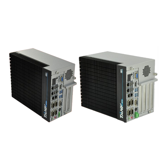
TANK -870-Q170 E mbedded S ys tem 1.1 Overview Figure 1-1: TANK-870-Q170 Series The TANK-870-Q170 Series is an embedded system for wide range temperature environments. It is powered by the 6th/7th generation Intel® Core™ processor, uses the Intel® Q170 chipset and supports two 260-pin DDR4 SDRAM SO-DIMM modules up to 64 GB (4GB memory preinstalled). -
Page 16: Model Variations
TANK -870-Q170 E mbedded S ys tem 1.2 Model Variations The model variations of the TANK-870-Q170 Series series are listed below. Model No. Expansion Slots TANK-870-Q170i-i5/4G/2A 2 x PCIe by 8 expansion, Intel® Core™ i5-6500TE 2.3GHz TANK-870-Q170i-i5/4G/2B 1 x PCIe by 16 & 1 x PCI expansion (up to 3.3 GHz, Quad Core, TDP TANK-870-Q170i-i5/4G/4A 2 x PCIe by 8 &... -
Page 17: Technical Specifications
TANK -870-Q170 E mbedded S ys tem 1.4 Tec hnic al S pecifications The TANK-870-Q170 Series technical specifications are listed in Table 1-2. S pec ific ations C has s is Black C + Silver C olor 2-slot: 121.5 x 255.2 x 205 Dimens ions (W xHxD) (mm) 4-slot: 154.8 x 255.2 x 205 Fanless... - Page 18 TANK -870-Q170 E mbedded S ys tem S pec ific ations 4 x RS-232 (2 x RJ-45, 2 x DB-9 w/ isolation) C OM P ort 2 x RS-232/422/485 (DB-9) 8-bit digital I/O, 4-bit input/4-bit output Digital I/O 1 x VGA 1 x HDMI+DP Dis play 1 x iDP (optional)
-
Page 19: Table 1-2: Technical Specifications
TANK -870-Q170 E mbedded S ys tem S pec ific ations i7-6700TE -20°C ~ 45°C with air flow (SSD), 10% ~ 95%, non-condensing Operating T emperature i5-6500TE -20°C ~ 60°C with air flow (SSD), 10% ~ 95%, non-condensing -40°C ~ 85°C with air flow (SSD), S torage T emperature 10% ~ 90%, non-condensing Half-sine wave shock 5G;... -
Page 20: Front Panel
TANK -870-Q170 E mbedded S ys tem 1.5 F ront P anel 1.5.1 TANK -870-Q170-2 s lot F ront P anel The front panel of the TANK-870-Q170 Series has the following features (Figure 1-2): Figure 1-2: TANK-870-Q170 Series Front Panel Connectors and buttons on the front panel include the following: 1 x 4-pin power DC jack for 9 V ~ 36 V power input ... - Page 21 TANK -870-Q170 E mbedded S ys tem 2 x RS-232/422/485 serial ports (DB-9) 2 x Gigabit Ethernet ports (RJ-45) 4 x USB 3.0 ports 4 x USB 2.0 ports 1 x Reset button 6 x LED indicators (Section 1.7) ...
-
Page 22: Tank-870-Q170-4 Slot Front Panel
TANK -870-Q170 E mbedded S ys tem 1.5.2 TANK -870-Q170-4 s lot F ront P anel The front panel of the TANK-870-Q170 Series has the following features (Figure 1-2): Figure 1-3: TANK-870-Q170 Series Front Panel Connectors and buttons on the front panel include the following: 1 x 4-pin power DC jack for 9 V ~ 36 V power input ... -
Page 23: Rear Panel
TANK -870-Q170 E mbedded S ys tem 4 x USB 2.0 ports 1 x Reset button 6 x LED indicators (Section 1.7) 1 x Power button 1 x VGA port 1 x HDMI+DP port 1 X DIO port ... -
Page 24: Figure 1-5: Tank-870-Q170 Series Led Indicators
TANK -870-Q170 E mbedded S ys tem Figure 1-5: TANK-870-Q170 Series LED Indicators The descriptions of each LED indicator are listed below. L E D Indic ator Des c ription The current power mode status is AT mode. AT Power Mode Controlled by the AT/ATX power mode switch. -
Page 25: Backplane Options
TANK -870-Q170 E mbedded S ys tem 1.8 B ac kplane Options The backplane options of the TANK-870-Q170 Series are shown below. Figure 1-6: HPE-2S86 (for 2A model) PWR1: Description +12 V +12 V Figure 1-7: HPE-4AS87 (for 4A model) Page 12... - Page 26 TANK -870-Q170 E mbedded S ys tem PWR1: Description +12 V +12 V MINI-PCIE1: Description Description PCIE_WAKE# VCC3 1.5 V WLAN_CLKREQ# CLK- Page 13...
-
Page 27: Figure 1-8: Hpe-2S87 (For 2B Model)
TANK -870-Q170 E mbedded S ys tem Description Description CLK+ PCIRST# VCC3 PCIRST# PCIE-RXN VCC3 PCIE-RXP 1.5 V SMBCLK PCIE-TXN SMBDATA PCIE-TXP USBD- USBD+ VCC3 VCC3 RF_LINK# BLUELED# 1.5 V VCC3 Figure 1-8: HPE-2S87 (for 2B model) Page 14... -
Page 28: Figure 1-9: Hpe-4S87 (For 4B Model)
TANK -870-Q170 E mbedded S ys tem PWR1: Description +12 V +12 V Figure 1-9: HPE-4S87 (for 4B model) PWR1: Page 15... - Page 29 TANK -870-Q170 E mbedded S ys tem Description +12 V +12 V MINI-PCIE1: Description Description PCIE_WAKE# VCC3 1.5 V WLAN_CLKREQ# CLK- CLK+ PCIRST# VCC3 PCIRST# PCIE-RXN VCC3 PCIE-RXP Page 16...
-
Page 30: Table 1-4: Supported Signals
TANK -870-Q170 E mbedded S ys tem Description Description 1.5 V SMBCLK PCIE-TXN SMBDATA PCIE-TXP USBD- USBD+ VCC3 VCC3 RF_LINK# BLUELED# 1.5 V VCC3 The supported signals of the backplane slots are listed below. B ac kplane S lot S ignal PCIe x16 PCIe x8 HP E -2S 86... -
Page 31: Table 1-5: Rated Voltage And Current
TANK -870-Q170 E mbedded S ys tem R ated V oltage R ated C urrent +5 V 4.0 A +12 V 2.5 A -12 V 0.1 A +3.3 V 5.0 A Table 1-5: Rated Voltage and Current WARNING: The system default power is 120 W. The maximum total power of the backplane to support expansion cards is 45 W. -
Page 32: Physical Dimensions
TANK -870-Q170 E mbedded S ys tem 1.9 P hys ic al Dimens ions The following sections describe the physical dimensions for each model of the TANK-870-Q170 Series. 1.9.1 TANK -870-Q170-2 s lot P hys ic al Dimens ions The physical dimensions of the TANK-870-Q170-2 slot are shown in Figure 1-11. Figure 1-10: TANK-870-Q170-2 slot Physical Dimensions (millimeters) Page 19... -
Page 33: Tank-870-Q170-4 Slot Physical Dimensions
TANK -870-Q170 E mbedded S ys tem 1.9.2 TANK -870-Q170-4 s lot P hys ic al Dimens ions The physical dimensions of the TANK-870-Q170-4 slot are shown in Figure 1-12. Figure 1-11: TANK-870-Q170-4 slot Physical Dimensions (millimeters) Page 20... -
Page 34: Unpacking
TANK -870-Q170 E mbedded S ys tem C hapter Unpac king Page 21... -
Page 35: Anti - Static Precautions
TANK -870-Q170 E mbedded S ys tem 2.1 Anti-s tatic P recautions WAR NING : Failure to take ESD precautions during installation may result in permanent damage to the TANK-870-Q170 Series and severe injury to the user. Electrostatic discharge (ESD) can cause serious damage to electronic components, including the TANK-870-Q170 Series. -
Page 36: Unpacking Checklist
TANK -870-Q170 E mbedded S ys tem 2.3 Unpac king C hec klis t NOT E : If some of the components listed in the checklist below are missing, please do not proceed with the installation. Contact the IEI reseller or vendor you purchased the TANK-870-Q170 Series from or contact an IEI sales representative directly. - Page 37 TANK -870-Q170 E mbedded S ys tem Quantity Item and P art Number Image S tandard HDMI Security Holder The following table lists the optional items that can be purchased separately. Optional European power cord (P/N: 32702-000400-200-RS) Power adapter, FSP120-ABBN2, 9NA1205302, Active PFC, Vin:90~264VAC, 120W, plug=6.5mm, cable=1500mm, Erp (no load 0.15W), Vout:19VDC, 4-pin DIN with lock, CCL, RoHS (P/N: 63040-010120-210-RS)
- Page 38 TANK -870-Q170 E mbedded S ys tem Optional DisplayPort to DisplayPort converter board (For iEi IDP connector) (P/N: DP-DP-R10) DisplayPort to HDMI converter board (For iEi IDP connector) (P/N: DP-HDMI-R10) DisplayPort to 24 bit dual channel LVDS converter board (For iEi IDP connector) (P/N: DP-LVDS-R10) DisplayPort to VGA converter board (For iEi IDP connector)
- Page 39 TANK -870-Q170 E mbedded S ys tem Optional OS Image with Windows® Embedded Standard 7 E 64-bit for TANK-870-Q170 Series, with DVD-ROM, RoHS (P/N: TANK-870-Q170-WES7E64-R10) OS Image with Windows Embedded Standard 10 E High End 64-bit for TANK-870-Q170-i7 Series, with DVD-ROM, RoHS (P/N: TANK-870-Q170-W10E64-H-R10) OS Image with Windows Embedded Standard 10 E...
-
Page 40: Installation
TANK -870-Q170 E mbedded S ys tem C hapter Ins tallation Page 27... -
Page 41: Installation Precautions
TANK -870-Q170 E mbedded S ys tem 3.1 Ins tallation P rec autions During installation, be aware of the precautions below: Read the user manual: The user manual provides a complete description of the TANK-870-Q170 Series, installation instructions and configuration options. -
Page 42: Figure 3-1: Unscrew The Cover
TANK -870-Q170 E mbedded S ys tem Figure 3-1: Unscrew the Cover Unplug the SATA signal and power cables connected to the TANK-870-Q170 S tep 2: Series, and then put the cover on a flat surface (Figure 3-2). Figure 3-2: Remove the Cover from TANK-870-Q170 Series Attach the HDD to the HDD bracket, and then slide the HDD to connect with the S tep 3: SATA connector (Figure 3-3). -
Page 43: System Fan Installation
TANK -870-Q170 E mbedded S ys tem Figure 3-3: HDD Installation Secure the HDD with the HDD bracket by four retention screws (Figure 3-4). S tep 4: Figure 3-4: HDD Retention Screws Reconnect the SATA signal and power cables to the TANK-870-Q170 Series. S tep 5: Reinstall the cover. -
Page 44: Mounting The System With Mounting Brackets
TANK -870-Q170 E mbedded S ys tem Loosen the two thumbscrews on the front panel, slide the cover outward, and S tep 1: then lift the cover up gently (Figure 3-1). S tep 2: Unplug the SATA signal and power cables connected to the TANK-870-Q170 Series, and then place the cover on a flat surface (Figure 3-2). -
Page 45: External Peripheral Interface Connectors
TANK -870-Q170 E mbedded S ys tem Align the two retention screw holes in each bracket with the corresponding S tep 2: retention screw holes on the bottom surface or the left side panel (Figure 3-6). Left Side Panel Figure 3-6: Mounting Bracket Retention Screws Secure the brackets to the system by inserting two retention screws into each S tep 3: bracket (Figure 3-6). -
Page 46: Acc Mode Selection
TANK -870-Q170 E mbedded S ys tem Power button Power DC jack Power terminal block RS-232 RS-232/422/485 3.5.1 AC C Mode S elec tion The ACC mode is designed for vehicle applications. The TANK-870-Q170 Series allows turning the ACC mode on or off. -
Page 47: At/Atx Power Mode Selection
TANK -870-Q170 E mbedded S ys tem 3.5.2 AT /AT X P ower Mode S elec tion The TANK-870-Q170 Series supports AT and ATX power modes. The setting can be made through the AT/ATX power mode switch on the external peripheral interface panel as shown below. -
Page 48: Digital Input/Output Connector
TANK -870-Q170 E mbedded S ys tem 3.5.4 Digital Input/Output C onnec tor The digital I/O connector provides programmable input and output for external devices. The pinouts for the digital I/O connector are listed in the table below. Figure 3-10: DIO Connector 3.5.5 HDMI/DP C onnec tor To connect the HDMI/DP devices, please plug in HDMI/DP connector in the right direction as shown below:... -
Page 49: Figure 3-11: Lan Connection
TANK -870-Q170 E mbedded S ys tem Figure 3-12: LAN Connection Insert the LAN cable RJ-45 connector. Once aligned, gently insert the LAN S tep 3: cable RJ-45 connector into the on-board RJ-45 connector. Figure 3-13: RJ-45 Ethernet Connector The RJ-45 Ethernet connector has two status LEDs, one green and one yellow. The green LED indicates activity on the port and the yellow LED indicates the port is linked. -
Page 50: Power Input, 3-Pin Terminal Block
TANK -870-Q170 E mbedded S ys tem 3.5.7 P ower Input, 3-pin Terminal B loc k The power connector connects the leads of a 9 V~36 V DC power supply into the terminal block. Make sure that the power and ground wires are attached to the correct sockets of the connector. -
Page 51: Rs-232/422/485 Serial Port Connectors
TANK -870-Q170 E mbedded S ys tem Figure 3-16: RJ-45 RS-232 Serial Device Connection Insert the serial connector. Insert the DB-9 connector of a serial device into S tep 3: the DB-9 connector on the RJ-45 to DB-9 COM port cable. Secure the connector. -
Page 52: Usb Connectors
TANK -870-Q170 E mbedded S ys tem Insert the serial connector. Insert the DB-9 connector of a serial device into S tep 2: the DB-9 connector on the external peripheral interface. See Figure 3-17. Figure 3-18: Serial Device Connector Secure the connector. Secure the serial device connector to the external S tep 3: interface by tightening the two retention screws on either side of the connector. -
Page 53: Vga Connector
TANK -870-Q170 E mbedded S ys tem Align the connectors. Align the USB device connector with one of the S tep 2: connectors. See Figure 3-19. Figure 3-20: USB Device Connection Insert the device connector. Once aligned, gently insert the USB device S tep 3: connector into the on-board connector. -
Page 54: Internal Peripheral Interface Connectors
TANK -870-Q170 E mbedded S ys tem Figure 3-21: VGA Connector Secure the connector. Secure the DB-15 VGA connector from the VGA S tep 4: monitor to the external interface by tightening the two retention screws on either side of the connector. Figure 3-22: VGA Connector 3.6 Internal P eripheral Interfac e C onnectors 3.6.1 iDP Module Ins tallation... -
Page 55: Figure 3-22: Internal Displayport Connector Location
TANK -870-Q170 E mbedded S ys tem Locate the internal DisplayPort connector. The location of the internal S tep 2: DisplayPort connector is shown in Figure 3-22. Figure 3-23: Internal DisplayPort Connector Location Secure the iDP module with the bracket by tightening the two retention screws S tep 3: on either side of the iDP module. -
Page 56: Figure 3-24: Idp Module Installation
TANK -870-Q170 E mbedded S ys tem Figure 3-25: iDP Module Installation Remove the retention screws on the expansion slot bracket. See Figure 3-25. S tep 5: Figure 3-26: Remove Expansion Slot Bracket Secure the iDP module with bracket to the system. S tep 6: Reinstall the cover. -
Page 57: Table 3-2: Idp Converter Cards
TANK -870-Q170 E mbedded S ys tem WARNING: Installing the iDP module will occupy one expansion slot. The following table lists the iDP converter cards that can be installed to the system. DisplayPort to HDMI converter board (for IEI iDP connector) (P/N: DP-HDMI-R10) DisplayPort to LVDS converter board (for IEI iDP... -
Page 58: Powering O N /Off The System
TANK -870-Q170 E mbedded S ys tem 3.7 P owering On/Off the S ys tem WARNING: Make sure a power supply with the correct input voltage is being fed into the system. Incorrect voltages applied to the system may cause damage to the internal electronic components and may also cause injury to the user. -
Page 59: Acc On Mode
TANK -870-Q170 E mbedded S ys tem Figure 3-28: Power Connectors L E D Indic ator Des c ription Standby mode. Power LED1 (Breathing Orange) Power-on mode. Power LED2 (Solid blue) Table 3-3: Power LED Indicators Description NOTE: The power LED turns off when the power cable is unplugged from the system. -
Page 60: Acc Off Mode
TANK -870-Q170 E mbedded S ys tem 3. If ACC signal jumps from high to low during the power on process, the system will soft shut down and shut down the system power after 10s. 4. When Power 1 < 9 V and Power 2 < 9 V, the system will soft shut down and shut down the system power after 10s. - Page 61 TANK -870-Q170 E mbedded S ys tem Click the driver file name on the page and you will be prompted with the S tep 3: following window. You can download the entire ISO file ( ), or click the small arrow to find an individual driver and click the file name to download ( ...
-
Page 62: System Motherboard
TANK -870-Q170 E mbedded S ys tem Chapter S ys tem Motherboard Page 49... -
Page 63: Overview
TANK -870-Q170 E mbedded S ys tem 4.1 Overview This chapter details all the jumpers and connectors of the system motherboard. 4.1.1 L ayout The figures below show all the connectors and jumpers of the system motherboard. The Pin 1 locations of the on-board connectors are also indicated in the diagram below. Figure 4-1: System Motherboard (Front) Figure 4-2: System Motherboard (Rear) Page 50... -
Page 64: Internal Peripheral Connectors
TANK -870-Q170 E mbedded S ys tem 4.2 Internal P eripheral C onnec tors The table below shows a list of the internal peripheral interface connectors on the system motherboard. Pinouts of these connectors can be found in the following sections. C onnec tor T ype L abel... -
Page 65: Battery Connector (Bat1)
TANK -870-Q170 E mbedded S ys tem 4.2.2 B attery C onnec tor (B AT 1) PIN NO. DESCRIPTION VBATT Table 4-3: Battery Connector Pinouts (BAT1) 4.2.3 B IOS P rogramming C onnec tor (J S P I1) PIN NO. DESCRIPTION PIN NO. -
Page 66: Ec Debug Connector (Cn4)
TANK -870-Q170 E mbedded S ys tem Table 4-6: DisplayPort connector Pinouts (DP1) 4.2.6 E C Debug C onnec tor (C N4) PIN NO. DESCRIPTION PIN NO. DESCRIPTION KSI0 KSO9 KSO0 KSO10 KSO1 KSO12 KSO2 KSI1 KSO3 KSO11 KSO4 KSI2 KSO5 KSI3 KSO6... -
Page 67: Led Connector (J2)
TANK -870-Q170 E mbedded S ys tem 4.2.9 L E D C onnec tor (J 2) PIN NO. DESCRIPTION PIN NO. DESCRIPTION +V3.3S_IO +V3.3A_EC_IO IRST_PD# IATX_LED# IPWRLED01# IPWRLED02# IIPMI_LED# ICPU_LED# IDISKLED# Table 4-10: LED Connector Pinouts (J2) 4.2.10 S ATA P ower C onnec tors (C N2, C N3) PIN NO. -
Page 68: Usb 3.0 Connectors (Usb3-1)
TANK -870-Q170 E mbedded S ys tem 4.2.12 US B 3.0 c onnec tors (US B 3-1) PIN NO. DESCRIPTION PIN NO. DESCRIPTION VCC_USB3_56 USB3_RX5_N_C USB3_RX5_P_C USB3P1_TXDN5_C USB3P1_TXDP5_C USB2P5_DM1_L USB2P5_DP1_L USB2P6_DP2_L USB2P6_DM2_L USB3P1_TXDP6_C USB3P1_TXDN6_C USB3_RX6_P_C USB3_RX6_N_C VCC_USB3_56 Table 4-13: USB 3.0 connectors Pinouts (USB3-1) 4.3 E xternal Interfac e P anel C onnec tors The table below shows a list of the external interface panel connectors on the system motherboard. -
Page 69: Audio Jack (Jaudio1)
TANK -870-Q170 E mbedded S ys tem 4.3.1 Audio J ac k (J AUDIO1) PIN NO. DESCRIPTION PIN NO. DESCRIPTION ILMIC1-CONN-L IJD_MIC ILMIC1-CONN-R ILFRONT-L IJD_FRONT ILFRONT-R Table 4-15: Audio Jack Pinouts (JAUDIO1) 4.3.2 DIO c onnec tor (DIO1) PIN NO. DESCRIPTION PIN NO. -
Page 70: Ethernet And Usb 2.0 Connectors (Lan2_Usb2)
TANK -870-Q170 E mbedded S ys tem DESCRIPTION DESCRIPTION ILAN_MDI3_DN ILAN1_1000- ILAN1_100- ILAN1_LINK_ACT- ILAN1_LINK_PWR Table 4-18: LAN Pinouts (LAN1) 4.3.4 E thernet and US B 2.0 C onnec tors (L AN2_US B 2) DESCRIPTION DESCRIPTION USBV9L DATA9_N DATA9_P IO_GND USBV9L DATA10_N DATA10_P IO_GND... -
Page 71: Power Connector (Pwr2)
TANK -870-Q170 E mbedded S ys tem 4.3.6 P ower C onnec tor (P W R 2) PIN NO. DESCRIPTION PIN NO. DESCRIPTION ACCON +VIN Table 4-22: Power Connector Pinouts (PWR1) 4.3.7 R S -232 S erial P ort C onnec tor (C OM1_2) PIN NO. -
Page 72: Usb 3.0 Connectors (Usb3_Cn1)
TANK -870-Q170 E mbedded S ys tem 7(16) 8(17) 9(18) Table 4-25: RS-232/422/485 Serial Port Connector Pinout (COM5_6) 4.3.10 US B 3.0 C onnec tors (US B 3_C N1) PIN NO. DESCRIPTION PIN NO. DESCRIPTION VCC_USB12 USB_PN1_C USB_PP1_C USB3_RX1_N_C USB3_RX1_P_C USB3_TX1_N_C USB3_TX1_P_C VCC_USB12... -
Page 73: Vga Connector (Vga1)
TANK -870-Q170 E mbedded S ys tem 4.3.12 V G A C onnec tor (V G A1) PIN NO. DESCRIPTION PIN NO. DESCRIPTION Green Blue VGAVCC HOTPLUG DDCDAT HSYNC VSYNC DDCCLK Table 4-28: VGA Connector Pinouts (VGA1) Page 60... -
Page 74: Bios
TANK -870-Q170 E mbedded S ys tem C hapter B IOS Page 61... -
Page 75: Introduction
TANK -870-Q170 E mbedded S ys tem 5.1 Introduc tion The BIOS is programmed onto the BIOS chip. The BIOS setup program allows changes to certain system settings. This chapter outlines the options that can be changed. NOTE: Some of the BIOS options may vary throughout the life cycle of the product and are subject to change without prior notice. -
Page 76: Getting Help
TANK -870-Q170 E mbedded S ys tem K ey F unc tion Decrease the numeric value or make changes Page Up key Increase the numeric value or make changes Page Dn key Decrease the numeric value or make changes Esc key Main Menu –... - Page 77 TANK -870-Q170 E mbedded S ys tem Save & Exit – Selects exit options and loads default settings. The following sections completely describe the configuration options found in the menu items at the top of the BIOS screen and listed above. Page 64...
-
Page 78: Main
TANK -870-Q170 E mbedded S ys tem 5.2 Main The Main BIOS menu (BIOS Menu 1) appears when the BIOS Setup program is entered. The Main menu gives an overview of the basic system information. Aptio Setup Utility – Copyright (C) 2016 American Megatrends, Inc. Main Advanced Chipset... -
Page 79: Advanced
TANK -870-Q170 E mbedded S ys tem The Main menu has two user configurable fields: S ys tem Date [x x/x x/xx] Use the System Date option to set the system date. Manually enter the day, month and year. S ys tem T ime [xx: xx: xx] ... -
Page 80: Trusted Computing
TANK -870-Q170 E mbedded S ys tem Aptio Setup Utility – Copyright (C) 2016 American Megatrends, Inc. Advanced > Trusted Computing Trusted Computing > ACPI Settings Settings > AMT Configuration > F81866 Super IO Configuration > RTC Wake Settings > Serial Port Console Redirection ---------------------- >... -
Page 81: Acpi Settings
TANK -870-Q170 E mbedded S ys tem S ec urity Devic e S upport [Dis able] Use the Security Device Support option to configure support for the security device. Disable Security device support is disabled. EFAULT Enable Security device support is enabled. -
Page 82: Amt Configuration
TANK -870-Q170 E mbedded S ys tem 5.3.3 AMT C onfiguration The AMT Configuration menu (BIOS Menu 5) allows the advanced power management options to be configured. Aptio Setup Utility – Copyright (C) 2016 American Megatrends, Inc. Advanced Intel AMT [Enabled] Enable/Disable Intel (R) Un-Configure ME... -
Page 83: F81866 Super Io Configuration
TANK -870-Q170 E mbedded S ys tem 5.3.4 F 81866 S uper IO C onfiguration Use the F81866 Super IO Configuration menu (BIOS Menu 6) to set or change the configurations for the serial ports. Aptio Setup Utility – Copyright (C) 2016 American Megatrends, Inc. Advanced F81866 Super IO Configuration Set Parameters of Serial... - Page 84 TANK -870-Q170 E mbedded S ys tem 5.3.4.1.1 S erial P ort 1 C onfiguration S erial P ort [E nabled] Use the Serial Port option to enable or disable the serial port. Disabled Disable the serial port ...
- Page 85 TANK -870-Q170 E mbedded S ys tem Enabled Enable the serial port EFAULT C hange S ettings [Auto] Use the Change Settings option to change the serial port IO port address and interrupt address. Auto The serial port IO port address and interrupt EFAULT address are automatically detected.
- Page 86 TANK -870-Q170 E mbedded S ys tem Auto The serial port IO port address and interrupt EFAULT address are automatically detected. IO=3E8h; IRQ=10 Serial Port I/O port address is 3E8h and the interrupt address is IRQ10 IO=3E8h; IRQ=3, Serial Port I/O port address is 3E8h and the 4, 7, 9, 10, 11 interrupt address is IRQ3, 4, 7, 9, 10, 11...
- Page 87 TANK -870-Q170 E mbedded S ys tem IO=2E8h; IRQ=3, Serial Port I/O port address is 2E8h and the 4, 7, 9, 10, 11 interrupt address is IRQ3, 4, 7, 9, 10, 11 IO=3E0h; IRQ=3, Serial Port I/O port address is 3E0h and the 4, 7, 9, 10, 11 interrupt address is IRQ3, 4, 7, 9, 10, 11 ...
- Page 88 TANK -870-Q170 E mbedded S ys tem Devic e Mode [R S 232] Use the Device Mode option to select the serial port mode. RS232 Enables serial port RS-232 support. EFAULT RS422 Enables serial port RS-422 support. ...
-
Page 89: Rtc Wake Settings
TANK -870-Q170 E mbedded S ys tem Devic e Mode [R S 232] Use the Device Mode option to select the serial port mode. RS232 Enables serial port RS-232 support. EFAULT RS422 Enables serial port RS-422 support. ... -
Page 90: Serial Port Console Redirection
TANK -870-Q170 E mbedded S ys tem Enabled If selected, the following appears with values that can be selected: *Wake up every day *Wake up date *Wake up hour *Wake up minute *Wake up second After setting the alarm, the computer turns itself on from a suspend state when the alarm goes off. -
Page 91: Console Redirection Settings
TANK -870-Q170 E mbedded S ys tem Aptio Setup Utility – Copyright (C) 2016 American Megatrends, Inc. Advanced COM1 Console Redirection Console Redirection [Disabled] Enable or Disable > Console Redirection Settings COM2 Console Redirection [Disabled] > Console Redirection Settings COM3 Console Redirection [Disabled] >... - Page 92 TANK -870-Q170 E mbedded S ys tem Aptio Setup Utility – Copyright (C) 2016 American Megatrends, Inc. Advanced COM1 Emulation: ANSI: Console Redirection Settings Extended ASCII char set. VT100: ASCII char set. Terminal Type [ANSI] VT100+: Extends VT100 to Bits per second [115200] support color, function Data Bits...
- Page 93 TANK -870-Q170 E mbedded S ys tem 57600 The transmission speed is 57600 115200 The transmission speed is 115200 EFAULT Data B its [8] Use the Data Bits option to specify the number of data bits. Sets the data bits at 7.
-
Page 94: Cpu Configuration
TANK -870-Q170 E mbedded S ys tem 5.3.7 C P U C onfiguration Use the CPU Configuration menu (BIOS Menu 11) to enter the CPU Information submenu or enable Intel Virtualization Technology. Aptio Setup Utility – Copyright (C) 2016 American Megatrends, Inc. Advanced CPU Configuration Enabled for Windows XP... - Page 95 TANK -870-Q170 E mbedded S ys tem Processor Cores: Lists the number of the processor core Hyper Threading Technology: Indicates if Intel Hyper Threading Technology is supported by the CPU. Intel VT-x Technology: Indicates if Intel VT-x Technology is supported by the ...
- Page 96 TANK -870-Q170 E mbedded S ys tem Intel Virtualization Tec hnology [Dis abled] Use the Intel Virtualization Technology option to enable or disable virtualization on the system. When combined with third party software, Intel Virtualization technology allows several OSs to run on the same system at the same time. ...
-
Page 97: Sata Configuration
TANK -870-Q170 E mbedded S ys tem 5.3.8 S ATA C onfiguration Use the SATA Configuration menu (BIOS Menu 12) to change and/or set the configuration of the SATA devices installed in the system. Aptio Setup Utility – Copyright (C) 2016 American Megatrends, Inc. Advanced SATA Controller(s) [Enabled]... -
Page 98: Usb Configuration
TANK -870-Q170 E mbedded S ys tem 5.3.9 US B C onfiguration Use the USB Configuration menu (BIOS Menu 13) to read USB configuration information and configure the USB settings. Aptio Setup Utility – Copyright (C) 2016 American Megatrends, Inc. Advanced USB Configuration Enables Legacy USB... -
Page 99: Iei Feature
TANK -870-Q170 E mbedded S ys tem Disabled Legacy USB support disabled Auto Legacy USB support disabled if no USB devices are connected 5.3.10 iE i F eature Use the iEi Feature menu (BIOS Menu 14) to configure the iEi features. Aptio Setup Utility –... -
Page 100: Iwdd H/W Monitor
TANK -870-Q170 E mbedded S ys tem 5.3.11 iW DD H/W Monitor The iWDD H/W Monitor menu (BIOS Menu 15) shows the operating temperature, fan speeds and system voltages. Aptio Setup Utility – Copyright (C) 2016 American Megatrends, Inc. Advanced PC Health Status If CPU Temperature reach Tcc... -
Page 101: Smart Fan Mode Configuration
TANK -870-Q170 E mbedded S ys tem +V5S +V12S +VDDQ MBATTERY_IN1_EC SBATTERY_A_EC Tc c Temperature [E nabled] Use the Tcc Temperature option to change the Tcc Temperature value. If CPU Temperature reaches Tcc Temperature then reduces CPU Frequency. Minimum Value: 40°C ... -
Page 102: Chipset
TANK -870-Q170 E mbedded S ys tem Manual Mode The fan spins at the speed set in the manual setting Auto Mode The fan adjusts its speed using these EFAULT settings: CPU_FAN1 Start Temperature CPU_FAN1 Off Temperature CPU_FAN1 Start PWM C P U_FAN1 S tart/Off Temperature ... -
Page 103: System Agent (Sa) Configuration
TANK -870-Q170 E mbedded S ys tem Aptio Setup Utility – Copyright (C) 2016 American Megatrends, Inc. Chipset > System Agent (SA) Configuration PCH Parameters > PCH-IO Configuration --------------------- : Select Screen ↑ ↓: Select Item Enter Select +/-: Change Opt. General Help Previous Values Optimized Defaults... -
Page 104: Graphics Configuration
TANK -870-Q170 E mbedded S ys tem Enabled Enable VT-d support. 5.4.1.1 G raphic s C onfiguration Use the Graphics Configuration (BIOS Menu 19) menu to configure the video device connected to the system. Aptio Setup Utility – Copyright (C) 2016 American Megatrends, Inc. Chipset Graphics Configuration Select which of... - Page 105 TANK -870-Q170 E mbedded S ys tem then only be used as graphics memory, and is no longer available to applications or the operating system. Configuration options are listed below: 128M 256M Default 512M DV MT Total G fx Mem [MAX] ...
-
Page 106: Peg Port Configuration
TANK -870-Q170 E mbedded S ys tem 5.4.1.2 P E G P ort C onfiguration Aptio Setup Utility – Copyright (C) 2016 American Megatrends, Inc. Chipset PEG Port Configuration Enable or Disable the Root Port PEG 0 :1 :0 Not Present Enabled Root Port [Auto] Max Link Speed... -
Page 107: Memory Configuration
TANK -870-Q170 E mbedded S ys tem Detec t Non-C omplianc e Devic e [Dis abled] Use the Detect Non-Compliance Device option to enable or disable detecting a non-compliance PCI Express device in the PEG. The following options are available: Disabled Default ... -
Page 108: Pch-Io Configuration
TANK -870-Q170 E mbedded S ys tem 5.4.2 P C H-IO C onfiguration Use the PCH-IO Configuration menu (BIOS Menu 22) to configure the PCH parameters. Aptio Setup Utility – Copyright (C) 2016 American Megatrends, Inc. Chipset Auto Power Button Status [Disabled(ATX)] High Definition Audio Restore AC Power Loss... -
Page 109: Pci Express Configuration
TANK -870-Q170 E mbedded S ys tem US B P ower S W 1 [+5V DUAL ] Use the USB Power SW1 BIOS option to configure the USB power source for the corresponding USB connectors. Sets the USB power source to +5V ... - Page 110 TANK -870-Q170 E mbedded S ys tem P C Ie S peed Use PCIe Speed option to select the speed type of the PCIe Mini slot. The following options are available: Auto Default Gen1 Gen2 Gen3 ...
-
Page 111: Hd Audio Configuration
TANK -870-Q170 E mbedded S ys tem 5.4.2.2 HD Audio C onfiguration Use the HD Audio Configuration submenu (BIOS Menu 24) to configure the High Definition Audio codec. Aptio Setup Utility – Copyright (C) 2016 American Megatrends, Inc. Chipset HD Audio Configuration Control Detection of the Azalia device. - Page 112 TANK -870-Q170 E mbedded S ys tem Aptio Setup Utility – Copyright (C) 2016 American Megatrends, Inc. Security Password Description Set Administrator Password If ONLY the Administrator’s password is set, then this only limits access to Setup and is only asked for when entering Setup. --------------------- If ONLY the User’s password is set, then this : Select Screen...
-
Page 113: Boot
TANK -870-Q170 E mbedded S ys tem 5.6 B oot Use the Boot menu (BIOS Menu 26) to configure system boot options. Aptio Setup Utility – Copyright (C) 2016 American Megatrends, Inc. Boot Boot Configuration Select the keyboard Bootup NumLock State [On] NumLock state Quiet Boot... - Page 114 TANK -870-Q170 E mbedded S ys tem Quiet B oot [E nabled] Use the Quiet Boot BIOS option to select the screen display when the system boots. Disabled Normal POST messages displayed Enabled OEM Logo displayed instead of POST messages EFAULT L aunc h P XE OpR OM [Dis abled] ...
-
Page 115: Save & Exit
TANK -870-Q170 E mbedded S ys tem 5.7 S ave & E xit Use the Save & Exit menu (BIOS Menu 27) to load default BIOS values, optimal failsafe values and to save configuration changes. Aptio Setup Utility – Copyright (C) 2016 American Megatrends, Inc. Save &... -
Page 116: Server Mgmt
TANK -870-Q170 E mbedded S ys tem S ave as Us er Defaults Use the Save as User Defaults option to save the changes done so far as user defaults. R es tore Us er Defaults Use the Restore User Defaults option to restore the user defaults to all the setup options. 5.8 S erver Mgmt Use the Server Mgmt menu (BIOS Menu 28) to access the server management menus. -
Page 117: System Event Log
TANK -870-Q170 E mbedded S ys tem 5.8.1.1 S ys tem E vent L og Use the System Event Log menu (BIOS Menu 29) to configure the event log. Aptio Setup Utility – Copyright (C) 2016 American Megatrends, Inc. Server Mgmt Enabling/Disabling Options Change this to anable or SEL Components... -
Page 118: Bmc Network Configuration
TANK -870-Q170 E mbedded S ys tem W hen S E L is F ull [Do Nothing] Use When SEL is FULL option to select options for reactions to a full SEL. The following options are available: Do Nothing Default ... -
Page 119: A Regulatory Compliance
TANK -870-Q170 E mbedded S ys tem Appendix R egulatory C omplianc e Page 106... - Page 120 TANK -870-Q170 E mbedded S ys tem DE C L AR AT ION OF C ONF OR MIT Y This equipment is in conformity with the following EU directives: EMC Directive (2004/108/EC, 2014/30/EU) Low-Voltage Directive (2006/95/EC, 2014/35/EU) RoHS II Directive (2011/65/EU, 2015/863/EU) ...
- Page 121 TANK -870-Q170 E mbedded S ys tem Eesti [Estonian] IEI Integration Corp deklareerib seadme seadme vastavust direktiivi 2014/53/EÜ põhinõuetele ja nimetatud direktiivist tulenevatele teistele asjakohastele sätetele. Español [Spanish] IEI Integration Corp declara que el equipo cumple con los requisitos esenciales y cualesquiera otras disposiciones aplicables o exigibles de la Directiva 2014/53/EU.
- Page 122 TANK -870-Q170 E mbedded S ys tem Magyar [Hungarian] IEI Integration Corp nyilatkozom, hogy a berendezés megfelel a vonatkozó alapvetõ követelményeknek és az 2014/53/EU irányelv egyéb elõírásainak. Polski [Polish] IEI Integration Corp oświadcza, że wyrobu jest zgodny z zasadniczymi wymogami oraz pozostałymi stosownymi postanowieniami Dyrektywy 2014/53/EU.
- Page 123 TANK -870-Q170 E mbedded S ys tem F C C WAR NING This equipment complies with Part 15 of the FCC Rules. Operation is subject to the following two conditions: This device may not cause harmful interference, and This device must accept any interference received, including interference ...
-
Page 124: B Bios Options
TANK -870-Q170 E mbedded S ys tem Appendix B IOS Options Page 111... - Page 125 TANK -870-Q170 E mbedded S ys tem Below is a list of BIOS configuration options in the BIOS chapter. System Date [xx/xx/xx] ......................66 System Time [xx:xx:xx] .......................66 Security Device Support [Disable] ..................68 ACPI Sleep State [S3 (Suspend to RAM)] ................68 ...
- Page 126 TANK -870-Q170 E mbedded S ys tem SATA Controller(s) [Enabled] .....................84 SATA Mode Selection [AHCI] ....................84 USB Devices .........................85 Legacy USB Support [Enabled] ..................85 Auto Recovery Function [Disabled] ...................86 PC Health Status ........................87 Tcc Temperature [Enabled] ....................88 ...
- Page 127 TANK -870-Q170 E mbedded S ys tem Save as User Defaults .......................103 Restore User Defaults .......................103 SEL Components [Enabled] ....................104 Erase SEL [No] ........................104 When SEL is Full [Do Nothing] ..................105 Configuration Address source [Unspecified] ..............105 ...
-
Page 128: C Terminology
TANK -870-Q170 E mbedded S ys tem Appendix T erminology Page 115... - Page 129 TANK -870-Q170 E mbedded S ys tem Audio Codec 97 (AC’97) refers to a codec standard developed by Intel® AC ’97 in 1997. Advanced Configuration and Power Interface (ACPI) is an OS-directed AC P I configuration, power management, and thermal management interface. Advanced Host Controller Interface (AHCI) is a SATA Host controller AHC I register-level interface.
- Page 130 TANK -870-Q170 E mbedded S ys tem Direct Memory Access (DMA) enables some peripheral devices to bypass the system processor and communicate directly with the system memory. Dual Inline Memory Modules are a type of RAM that offer a 64-bit data DIMM bus and have separate electrical contacts on each side of the module.
- Page 131 TANK -870-Q170 E mbedded S ys tem Liquid crystal display (LCD) is a flat, low-power display device that L C D consists of two polarizing plates with a liquid crystal panel in between. Low-voltage differential signaling (LVDS) is a dual-wire, high-speed L V DS differential electrical signaling system commonly used to connect LCD displays to a computer.
-
Page 132: D Safety Precautions
TANK -870-Q170 E mbedded S ys tem Appendix S afety P rec autions Page 119... -
Page 133: Safety Precautions
TANK -870-Q170 E mbedded S ys tem D.1 S afety P rec autions WAR NING : The precautions outlined in this appendix should be strictly followed. Failure to follow these precautions may result in permanent damage to the TANK-870-Q170 Series. Please follow the safety precautions outlined in the sections that follow: D.1.1 G eneral S afety P rec autions Please ensure the following safety precautions are adhered to at all times. -
Page 134: Anti-Static Precautions
TANK -870-Q170 E mbedded S ys tem D.1.2 Anti-s tatic P rec autions WAR NING : Failure to take ESD precautions during the installation of the TANK-870-Q170 Series may result in permanent damage to the TANK-870-Q170 Series and severe injury to the user. Electrostatic discharge (ESD) can cause serious damage to electronic components, including the TANK-870-Q170 Series. -
Page 135: Product Disposal
TANK -870-Q170 E mbedded S ys tem D.1.3 P roduc t Dis pos al CAUTION: Risk of explosion if battery is replaced by and incorrect type. Only certified engineers should replace the on-board battery. Dispose of used batteries according to instructions and local regulations. -
Page 136: Maintenance And Cleaning
TANK -870-Q170 E mbedded S ys tem D.2.1 Maintenanc e and C leaning Prior to cleaning any part or component of the TANK-870-Q170 Series, please read the details below. The interior of the TANK-870-Q170 Series does not require cleaning. Keep ... - Page 137 TANK -870-Q170 E mbedded S ys tem Cotton swabs - Cotton swaps moistened with rubbing alcohol or water are excellent tools for wiping hard to reach areas. Foam swabs - Whenever possible, it is best to use lint free swabs such as ...
-
Page 138: E Digital I/O Interface
TANK -870-Q170 E mbedded S ys tem Appendix Digital I/O Interfac e Page 125... -
Page 139: Introduction
TANK -870-Q170 E mbedded S ys tem E .1 Introduc tion The DIO connector on the TANK-870-Q170 Series is interfaced to GPIO ports on the Super I/O chipset. The DIO has both 4-bit digital inputs and 4-bit digital outputs. The digital inputs and digital outputs are generally control signals that control the on/off circuit of external devices or TTL devices. -
Page 140: Assembly Language Sample
TANK -870-Q170 E mbedded S ys tem E .2 As s embly L anguage S ample 1 AX, 6F08H ;setting the digital port as input AL low byte = value AH – 6FH Sub-function: AL – 9 :Set the digital port as OUTPUT :Digital I/O input value E .3 As s embly L anguage S ample 2 AX, 6F09H... -
Page 141: Assembly Language Samplef Hazardous Materials Disclosure
TANK -870-Q170 E mbedded S ys tem Appendix Hazardous Materials Dis c los ure Page 128... - Page 142 TANK -870-Q170 E mbedded S ys tem The details provided in this appendix are to ensure that the product is compliant with the Peoples Republic of China (China) RoHS standards. The table below acknowledges the presences of small quantities of certain materials in the product, and is applicable to China RoHS only.
- Page 143 TANK -870-Q170 E mbedded S ys tem 此附件旨在确保本产品符合中国 RoHS 标准。以下表格标示此产品中某有毒物质的含量符 合中国 RoHS 标准规定的限量要求。 本产品上会附有”环境友好使用期限”的标签,此期限是估算这些物质”不会有泄漏或突变”的 年限。本产品可能包含有较短的环境友好使用期限的可替换元件,像是电池或灯管,这些元 件将会单独标示出来。 部件名称 有毒有害物质或元素 铅 汞 镉 六价铬 多溴联苯 多溴二苯 醚 (P b) (Hg) (C d) (C R (V I)) (P B B ) (P B DE ) 壳体...
Need help?
Do you have a question about the TANK -870-Q170 S eries and is the answer not in the manual?
Questions and answers