Table of Contents
Advertisement
Advertisement
Table of Contents

Related Manuals for Extreme Networks ExtremeAnalytics PV-A-305


Summary of Contents for Extreme Networks ExtremeAnalytics PV-A-305
- Page 1 ® ExtremeAnalytics PV-A-305 Installation Guide 9035117-02 Published April 2018...
- Page 2 Copyright © 2018 Extreme Networks All rights reserved. Legal Notice Extreme Networks, Inc. reserves the right to make changes in specifications and other information contained in this document and its website without prior notice. The reader should in all cases consult representatives of Extreme Networks to determine whether any such changes have been made.
-
Page 3: Table Of Contents
Table of Contents About This Guide........................4 Text Conventions...................................4 Related Publications................................5 Getting Help.....................................5 Providing Feedback to Us..............................5 Chapter 1: Engine Overview and Setup...................7 Kit Contents..................................... 7 Specifications..................................7 Front Panel Features................................9 Back Panel Features................................10 Removing and Installing the Front Bezel........................11 Installing the Engine into a Rack..........................12 Chapter 2: Configuration......................14 Pre-Configuration Tasks.............................. -
Page 4: About This Guide
About This Guide This document describes the installation and initial configuration of the Extreme Application Analytics PV-A-305 hardware engine. This document is intended for experienced network administrators who are responsible for implementing and maintaining communications networks. Text Conventions The following tables list text conventions that are used throughout this guide. Table 1: Notice Icons Icon Notice Type... -
Page 5: Related Publications
The Hub — A forum for Extreme customers to connect with one another, answer questions, and share ideas and feedback. This community is monitored by Extreme Networks employees, but is not intended to replace specific guidance from GTAC. Before contacting Extreme Networks for technical support, have the following information ready: •... - Page 6 Ideas for improvements to our documentation so you can find the information you need faster. • Broken links or usability issues. If you would like to provide feedback to the Extreme Networks Information Development team about this document, please contact us using our short online feedback form.
-
Page 7: Chapter 1: Engine Overview And Setup
Products Product Safety and Regulatory Compliance, available at the following links: http://download.intel.com/support/motherboards/server/sb/g23122003_safetyregulatory.pdf http://www.extremenetworks.com/support/documentation/ Kit Contents The PV-A-305 engine ships with the following components: • Extreme Networks URL card • Front bezel label • A rack mounting kit • Two rack handles and appropriate screws •... - Page 8 Engine Overview and Setup Table 3: PV-A-305 Physical Specifications (continued) Architecture 2400 MHz Dual Ranked Registered (RDIMM) ECC DDR4 Memory module capacities 4 GB DIMMs Minimum RAM (included) 64 GB (sixteen 4 GB DIMMs) Maximum RAM 128 GB (thirty-two 4 GB RDIMMs) RAID Configuration RAID 1 with BBU Drives...
-
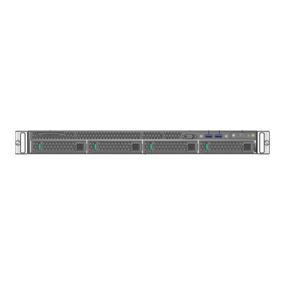
Page 9: Front Panel Features
Engine Overview and Setup Table 4: PV-A-305 Environmental Specifications (continued) Parameter Limits Storage humidity 50% to 90%, non-condensing at 28°C (82°F) Vibration, unpackaged 5 Hz to 500 Hz, 2.20 g RMS random Shock, operating Half sine, 2 g-force peak, 11 milliseconds Shock, unpackaged Trapezoidal, 25 g, velocity change 136 inches/second (40 lb to <... -
Page 10: Back Panel Features
Engine Overview and Setup Mgmt port activity LED Hard drive activity LED Not used Not used System cold reset button Not used Hard Drive LED Indicator Patterns The hard drive has two LED indicators visible from the front of the system: one is a green LED for disk activity, and the other is amber and indicates hard drive status. -
Page 11: Removing And Installing The Front Bezel
Engine Overview and Setup Table 7: RJ45 Port LEDs (Management Port) LED Type LED Pattern Status Indication Network speed (right) 10 Mbps Amber 100 Mbps Green 1000 Mbps Link activity (left) No link Solid Green Active link Blinking Green Data traffic activity Power Supply Status Indicator Patterns The engine has two power supplies, supplying hot-pluggable power redundancy. -
Page 12: Installing The Engine Into A Rack
Engine Overview and Setup 3 Rotate the front bezel counterclockwise to release the latches on the right end from the rack handle. Installing the Front Bezel Note Before installing the bezel, you must install the rack handles. See Installing the Engine into a Rack on page 12. - Page 13 Engine Overview and Setup Table 9: Recommended Torque Values by Screw Size Screw Size Torque in Pounds Bit Size English Metric Nominal 1.42 1.57 2 – 56 2.85 3.15 4 – 40 4.75 5.25 6 – 32 8.55 9.45 8 – 32 17.10 18.0 18.90...
-
Page 14: Chapter 2: Configuration
Configuration Pre-Configuration Tasks Configuring the Application Analytics Engine Launching the Application Analytics Application Adding the Application Analytics Engine Changing Application Analytics Engine Settings Upgrading Application Analytics Engine Software Once the PV-A-305 engine is physically installed into a rack, you need to connect a monitor and a USB keyboard, connect the power cord and network cable, and power it on (see Figure 1 on page 9 and... - Page 15 Configuration ================================================================= Extreme Networks - Application Analytics Engine - Welcome to the Application Analytics Engine Setup ================================================================= Please enter the information as it is requested to continue with the configuration. Typically a default value is displayed in brackets. Pressing the [enter] key without entering a new value will use the bracketed value and proceed to the next item.
- Page 16 Configuration 1. Single Interface With Tunnel A single interface is used for both management and monitoring traffic. A GRE Tunnel will be configured for traffic monitoring. Suitable for feeds from Coreflow switches. 2. Interface Mirrored Separate interfaces are configured for management and monitoring traffic. The monitoring interface will put into tap mode for traffic monitoring.
- Page 17 Configuration 8 Specify one or more tap ports. If you have an installed the optional PV-A-305-10G-UG I/O module, the ports are eth4 and eth5. For each line, type the requested configuration information and press [Enter]. ====================================================================== Application Analytics Engine Network Configuration for Tap Mode ====================================================================== Enter the interface name for Tap Mode [eth1]: eth4...
- Page 18 Configuration Enter the SRC IP address for the GRE Tunnel [10.54.222.117]: Enter the DST IP address for the GRE Tunnel [192.168.1.1]: 10.54.2.117 Add another GRE Tunnel (y/n) [n]? n 11 A screen appears asking you to confirm your network setting. Enter 0 to accept the settings. The following example shows the Confirm Network Settings screen for deployment mode 1.
- Page 19 Configuration ================================================================= The following information will be used to configure SNMP management of this device. The SNMP information entered here must be used to contact this device with remote management applications such as Extreme Management Center Console. ================================================================= Please enter the SNMP user name [snmpuser]: Please enter the SNMP authentication credential [snmpauthcred]: Please enter the SNMP privacy credential [snmpprivcred]: 13 A summary screen appears asking you to accept your SNMP Configuration settings.
- Page 20 Configuration ================================================================= The current system date and time is: Thu Oct 28 09:34:08 2013 Please enter the values for date and time as directed where input is expected in the following format: - 2 digit month of year - 2 digit day of month YYYY - 4 digit year - 2 digit hour of day using a 24 hour clock - 2 digit minute of hour...
-
Page 21: Launching The Application Analytics Application
The Application Analytics application software is automatically installed. This may take a few minutes. When the installation is complete, you see the following screen. ================================================================= Extreme Networks - Application Analytics Engine - Setup Complete ================================================================= Setup of the Application Analytics Engine is now complete. The engine is now operational and ready to accept remote connections. - Page 22 Configuration Select the Configuration tab in the Analytics tab. 2 Click the Menu icon and select Add Engine. The Add Application Analytics Engine window displays. ExtremeAnalytics® PV-A-305 Installation Guide for version 8.1...
-
Page 23: Changing Application Analytics Engine Settings
Configuration 3 Enter the IP Address of the eth0 interface and the Name of the Application Analytics engine. 4 Select the appropriate SNMP Profile from the Profile drop-down menu. 5 Click OK. 6 Select Enforce Engine from the drop-down menu. The Application Analytics engine is added to Management Center. -
Page 24: Upgrading Application Analytics Engine Software
Configuration Changing Date and Time Settings To enable or disable using NTP to configure the engine date and time, or to manually set the date and time on the engine, enter the following command at the engine CLI: /usr/postinstall/dateconfig This starts the date and time configuration script and allows you to change the settings. Changing the Management Center Server IP Address To change the IP address of the Management Center server, enter the following command at the engine CLI:... - Page 25 Configuration 5 Select a version. 6 Download the following image file and extract the file to a directory on your system: Application Analytics Engine Upgrade (BIN) 2 Use FTP, SCP, or a shared mount point, to copy the upgrade file to the Application Analytics engine. 3 SSH to the engine.
-
Page 26: Appendix A: Reinstalling Engine Software
Reinstalling Engine Software In the event a software reinstall becomes necessary, use this procedure. Be aware that this procedure reformats the hard drive and reinstalls all the engine software, the operating system, and all related Linux packages. Connect a monitor and a USB keyboard to the Application Analytics engine prior to performing these steps. - Page 27 Reinstalling Engine Software 10 Verify the USB flash drive is available as a boot option: a Press F2 to open the BIOS Setup Menu when prompted, as shown in the figure below. b Press the right arrow button to select the Boot Options tab. c Select Internal EFI Shell as Boot Option #1 in the boot menu.
-
Page 28: Glossary
Glossary ad hoc mode An 802.11 networking framework in which devices or stations communicate directly with each other, without the use of an AP. Address Resolution Protocol is part of the TCP/IP suite used to dynamically associate a device's physical address (MAC address) with its logical address (IP address). - Page 29 WEP keys. Unlike EAP-TLS, EAP-TTLS requires only server-side certificates. (See also PEAP (Protected Extensible Authentication Protocol).) ESRP Extreme Standby Router Protocol is an Extreme Networks-proprietary protocol that provides redundant Layer 2 and routing services to users. Extreme Access Control EAC, formerly NAC ™...
- Page 30 Glossary This can be used to better understand customer behavior on the network, identify the level of user engagement, and assure business application delivery to optimize the user experience. The software also provides visibility into network and application performance allowing IT to pinpoint and resolve performance issues in the infrastructure whether they are caused by the network, application, or server.
- Page 31 Glossary over a wide band of frequencies. This technique reduces interference. If synchronized properly, a single logical channel is maintained. (Compare with DSSS (Direct-Sequence Spread Spectrum).) IBSS An IBSS is the 802.11 term for an ad hoc network. See ad hoc mode. Message Integrity Check (or Code), also called ‘Michael’, is part of WPA and TKIP.
-
Page 32: Index
Index Numerics 1U engine:back panel connections 10 1U engine:front panel features 9 1U engine:kit contents 7 1U engine:specifications 7 2U Multi-Gigabit engine:Installing and removing bezel 11 2U Multi-Gigabit engine:rack installation 12 Adding Application Analytics Engine 21 Back panel features:1U engine 10 Bezel:Installing and removing:2U Multi-Gigabit engine 11 conventions notice icons 4 text 4 documentation feedback 5...
Need help?
Do you have a question about the ExtremeAnalytics PV-A-305 and is the answer not in the manual?
Questions and answers