Extreme Networks Extreme Management Center ExtremeControl IA-A-25 Installation Manual
Extreme access control engine
Hide thumbs
Also See for Extreme Management Center ExtremeControl IA-A-25:
- Installation manual (31 pages)

Related Manuals for Extreme Networks Extreme Management Center ExtremeControl IA-A-25


Summary of Contents for Extreme Networks Extreme Management Center ExtremeControl IA-A-25
- Page 1 ExtremeControl IA-A-25 Installation Guide ® Extreme Management Center Extreme Access Control Engine 9035113-01 Published March 2018...
- Page 2 Copyright © 2018 Extreme Networks All rights reserved. Legal Notice Extreme Networks, Inc. reserves the right to make changes in specifications and other information contained in this document and its website without prior notice. The reader should in all cases consult representatives of Extreme Networks to determine whether any such changes have been made.
-
Page 3: Table Of Contents
Table of Contents About this Guide........................4 Text Conventions...................................4 Providing Feedback to Us..............................4 Getting Help.....................................5 Related Publications................................5 Chapter 1: Engine Overview and Setup.................. 6 Kit Contents..................................... 6 Specifications..................................6 Front Panel Features................................8 Back Panel Features................................9 Removing and Installing the Front Bezel.........................10 Installing the Engine into a Rack........................... -
Page 4: About This Guide
About this Guide This document describes the installation and initial configuration of the Extreme Networks ® Extreme Access Control IA–A–25 hardware engine. This document is intended for experienced network administrators who are responsible for implementing and maintaining communications networks. Text Conventions The following tables list text conventions that are used throughout this guide. -
Page 5: Getting Help
Ideas for improvements to our documentation so you can find the information you need faster. • Broken links or usability issues. If you would like to provide feedback to the Extreme Networks Information Development team about this document, please contact us using our short online feedback form. -
Page 6: Chapter 1: Engine Overview And Setup
Products Product Safety and Regulatory Compliance, available at the following links: http://download.intel.com/support/motherboards/server/sb/g23122003_safetyregulatory.pdf http://www.extremenetworks.com/support/documentation/ Kit Contents The engine ships with the following components: • Extreme Networks URL card • Front bezel label • A rack mounting kit • Two rack handles and appropriate screws •... - Page 7 Engine Overview and Setup Table 3: IA-A-25 Physical Specifications (continued) Memory module capacities 4 GB DIMMs Minimum RAM (included) 16 GB (four 4 GB DIMMs) Maximum RAM 48 GB (twenty-four 2 GB RDIMMs) Drives Hard drives One 150 GB SSD hard drive Connectors Back Four RJ-45...
-
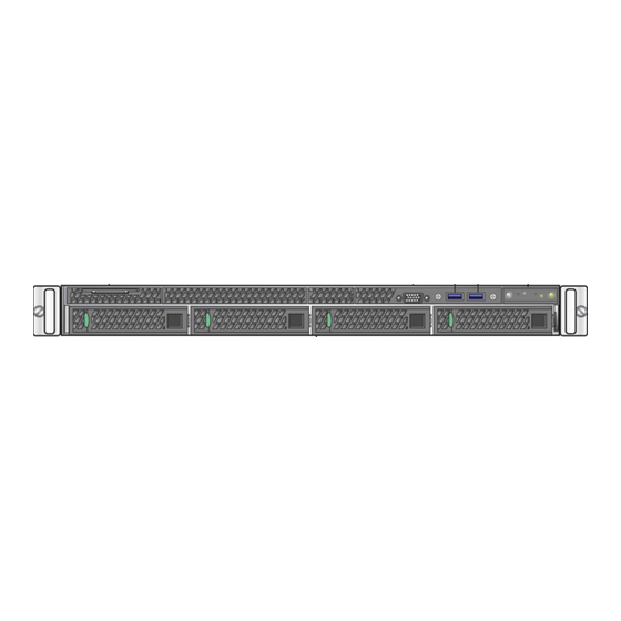
Page 8: Front Panel Features
Engine Overview and Setup Table 4: IA-A-25 Environmental Specifications (continued) Parameter Limits Shock, operating Half sine, 2 g-force peak, 11 milliseconds Shock, unpackaged Trapezoidal, 25 g, velocity change 136 inches/second (40 lb to < 80 Shock, packaged Non-palletized free fall in height 24 inches (40 lb to < 80 lb) ±12 KV except I/O port ±8 KV per Intel®... -
Page 9: Back Panel Features
Engine Overview and Setup Mgmt port activity LED Hard drive activity LED Not used Not used System cold reset button Not used Hard Drive LED Indicator Patterns The hard drive has two LED indicators visible from the front of the system: one is a green LED for disk activity, and the other is amber and indicates hard drive status. -
Page 10: Removing And Installing The Front Bezel
Engine Overview and Setup Table 7: RJ45 Port LEDs (Management Port) LED Type LED Pattern Status Indication Network speed (right) 10 Mbps Amber 100 Mbps Green 1000 Mbps Link activity (left) No link Solid green Active link Blinking green Data traffic activity Power Supply Status Indicator Patterns The engine has two power supplies, supplying hot-pluggable power redundancy. -
Page 11: Installing The Engine Into A Rack
Engine Overview and Setup 3 Rotate the front bezel counterclockwise to release the latches on the right end from the rack handle. Installing the Front Bezel Note Before installing the bezel, you must install the rack handles. See Installing the Engine into a Rack on page 11. - Page 12 Engine Overview and Setup Torque Values The following table describes the recommended torque values to use when installing the engine using standard threaded fastener machine screws and bolts. Table 9: Recommended Torque Values by Screw Size Screw Size Torque in Pounds Bit Size English Metric...
-
Page 13: Chapter 2: Configuration
Login as root with no password, and press [Enter]. The following screen appears. ================================================================= Extreme Networks - Access Control Engine - Welcome to the Access Control Engine 7.1.2.11 Setup ================================================================= Please enter the information as it is requested to continue with the configuration. - Page 14 Configuration At the end of the setup process, the existing settings will be displayed and opportunity will be provided to correct any errors. ================================================================= Press [enter] to begin setup or CTRL-C to exit: 2 Press [Enter] to begin the setup. The Root Password Configuration screen appears: ================================================================= Root Password Configuration...
- Page 15 Configuration ================================================================= The engine date and time can be set manually or using an external Network Time Protocol (NTP) server. It is strongly recommended that NTP is used to configure the date and time to ensure accuracy of time values for SNMP communications and logged events. Up to 5 server IP addresses may be entered if NTP is used.
- Page 16 Enter selection [0]: When you see the following screen, configuration is complete. ================================================================= Extreme Networks - Access Control Engine - Setup Complete ================================================================= Setup of the Access Control is now complete. Details of the engine setup process are located in the log files in the /var/log/install directory.
-
Page 17: Changing Engine Settings
Configuration If you have reinstalled your Extreme Access Control engine software, use Management Center to enforce the engine. Enforcing writes your Management Center configuration information to the engine. Changing Engine Settings This section provides instruction for changing your engine settings following your initial engine configuration, should the need arise. - Page 18 Configuration 6 Click Static Routes in the Interface Summary section to open the Static Route Configuration window, where you can add or edit the static routes used for advanced routing configuration. For more information, see the "Static Route Configuration Window" topic in the Management Center online Help.
-
Page 19: Upgrading Engine Software
Configuration /usr/postinstall/dateconfig This starts the date and time configuration script and allow you to change the settings. Upgrading Engine Software Upgrades to the Extreme Access Control engine software are available on the Extreme Portal: https:// extremeportal.force.com/. After entering your email address and password, you will be on the Support page. -
Page 20: Chapter 3: Reinstalling Engine Software
Reinstalling Engine Software Use the procedure in this chapter to reinstall the engine software, in the event a software reinstall becomes necessary. Be aware that this procedure reformats the hard drive and reinstalls all the engine software, the operating system, and all related Linux packages. You will need to connect a monitor and a USB keyboard to the engine prior to performing these steps. -
Page 21: Appendix A: Product Regulatory And Compliance Information
Product Regulatory and Compliance Information For complete regulatory compliance and safety information, refer to the document Intel® Server Products Product Safety and Regulatory Compliance, available at the following links: http://download.intel.com/support/motherboards/server/sb/g23122003_safetyregulatory.pdf https://www.extremenetworks.com/support/documentation/ Federal Communications Commission (FCC) Notice This product has been tested and found to comply with the limits for a class A digital device, pursuant to Part 15 of the FCC rules. - Page 22 Product Regulatory and Compliance Information CE Notice This product has been determined to be in compliance with 2006/95/EC (Low Voltage Directive), 2004/108/EC (EMC Directive). VCCI Notice This is a class A product based on the standard of the Voluntary Control Council for Interference by Information Technology Equipment (VCCI).
- Page 23 Product Regulatory and Compliance Information The symbol above indicates that separate collection of electrical and electronic equipment is required. 2 When this product has reached the end of its serviceable life, it cannot be disposed of as unsorted municipal waste. It must be collected and treated separately. 3 It has been determined by the European Parliament that there are potential negative effects on the environment and human health as a result of the presence of hazardous substances in electrical and electronic equipment.
- Page 24 Product Regulatory and Compliance Information Declaration of Conformity Application of Council Directive(s): 2004/108/EC 2006/95/EC 2011/65/EU Manufacturer’s Name: Extreme Networks, Inc. ExtremeControl IA-A-25 Installation Guide for version 8.1...
- Page 25 Product Regulatory and Compliance Information Manufacturer’s Address: 145 Rio Robles San Jose, CA 95134 European Representative Name: Enterasys Networks Limited European Representative Address: Nexus House, Newbury Business Park London Road, Newbury Berkshire RG14 2PZ, England Conformance to Directive(s)/Product EC Directive 2004/108/EC EN55022:2006 A1:2007 EN Standards: 55024:1998 A1:2001 A2:2003 EN 61000-3-2:2006 A1:2009 A2:2009 EN 61000-3-3:2008 EC Directive 2006/95/EC EN...
-
Page 26: Glossary
Glossary ad hoc mode An 802.11 networking framework in which devices or stations communicate directly with each other, without the use of an AP. Address Resolution Protocol is part of the TCP/IP suite used to dynamically associate a device's physical address (MAC address) with its logical address (IP address). - Page 27 WEP keys. Unlike EAP-TLS, EAP-TTLS requires only server-side certificates. (See also PEAP (Protected Extensible Authentication Protocol).) ESRP Extreme Standby Router Protocol is an Extreme Networks-proprietary protocol that provides redundant Layer 2 and routing services to users. Extreme Access Control EAC, formerly NAC ™...
- Page 28 Glossary This can be used to better understand customer behavior on the network, identify the level of user engagement, and assure business application delivery to optimize the user experience. The software also provides visibility into network and application performance allowing IT to pinpoint and resolve performance issues in the infrastructure whether they are caused by the network, application, or server.
- Page 29 Glossary IBSS An IBSS is the 802.11 term for an ad hoc network. See ad hoc mode. Message Integrity Check (or Code), also called ‘Michael’, is part of WPA and TKIP. The MIC is an additional 8-byte code inserted before the standard 4-byte ICV appended in by standard WEP to the 802.11 message.
-
Page 30: Index
Index Numerics 1U appliance:back panel connections 9 1U appliance:front panel features 8 1U appliance:kit contents 6 1U appliance:specifications 6 2U Multi-Gigabit appliance:Installing and removing bezel 10 2U Multi-Gigabit appliance:rack installation 11 Back panel features:1U appliance 9 Bezel:Installing and removing:2U Multi-Gigabit appliance 10 Changing:Basic Network Configuration 18 Changing:TAG Settings 17 conventions notice icons 4 text 4 documentation...
Need help?
Do you have a question about the Extreme Management Center ExtremeControl IA-A-25 and is the answer not in the manual?
Questions and answers