
Subscribe to Our Youtube Channel
Related Manuals for Extreme Networks 9920


Summary of Contents for Extreme Networks 9920
- Page 1 9920 Network Packet Broker Hardware Installation Guide 9037024-00 Rev. AB December 2022...
- Page 2 Copyright © 2022 Extreme Networks, Inc. Legal Notice Extreme Networks, Inc. reserves the right to make changes in specifications and other information contained in this document and its website without prior notice. The reader should in all cases consult representatives of Extreme Networks to determine whether any such changes have been made.
-
Page 3: Table Of Contents
Power Supplies for Use with the Extreme 9920...................11 AC power supply..............................12 DC power supply..............................13 DC power cable..............................13 Fan Modules for Use with the Extreme 9920....................13 Fan speed................................14 Interface Module for Use with the Extreme 9920..................16 Port Partioning..............................18 FEC Configuration Support ......................... - Page 4 Install the Device and the Components....................33 Safety Considerations for Installation......................33 What You Will Need for the Installation......................34 Install the Extreme 9920 in an Equipment Rack..................34 Ground the Chassis..............................37 Install an Interface Module............................ 38 Install an AC Power Supply...........................39 Connect an AC Power Supply........................
- Page 5 Table of Contents Select Power Supply Cords..........................69 Battery Notice................................70 Battery Warning - Taiwan............................70 EMC Warnings................................71 Taiwan BSMI Warning............................71 China CCC Warning............................71 Japan (VCCI Class A)..............................71 Korea EMC Statement.............................. 71 Index................................72 9920 Network Packet Broker Hardware Installation Guide...
-
Page 6: Preface
See the and the for information about configuring Extreme Networks devices. Note If the information in an installation note or release note shipped with your Extreme Networks equipment differs from the information in this guide, follow the installation or release note. - Page 7 Default responses to system prompts are enclosed in square brackets. { x | y | z } A choice of required parameters is enclosed in curly brackets separated by vertical bars. You must select one of the options. 9920 Network Packet Broker Hardware Installation Guide...
-
Page 8: Terminology
Providing Feedback The Information Development team at Extreme Networks has made every effort to ensure the accuracy and completeness of this document. We are always striving to improve our documentation and help you work better, so we want to hear from you. -
Page 9: Subscribe To Product Announcements
Extreme Optics Compatibility Other resources such as white papers, data sheets, and case studies Extreme Networks offers product training courses, both online and in person, as well as specialized certifications. For details, visit www.extremenetworks.com/education/. 9920 Network Packet Broker Hardware Installation Guide... -
Page 10: Extreme 9920 Overview
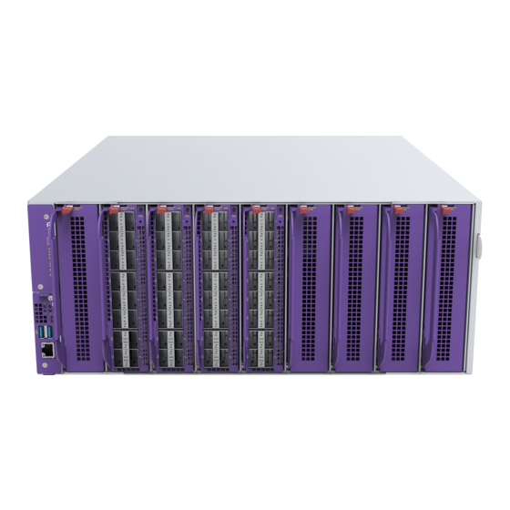
Works in tandem with Extreme Visibility Manager. The Extreme 9920 is a high density chassis in a 4U vertically oriented configuration. The Extreme 9920 supports up to 256 multispeed ports ranging from 10 Gb to 100 Gb, and aggregates and monitors up to 12.8 Tbps of total traffic. -
Page 11: Management
Figure 1: 9920 Network Packet Broker Management A Type A USB console port on the front panel of the Extreme 9920 connects the chassis to a laptop or PC for local management functions. A Mini-B USB console serial port on the front panel can also be used for management functions. -
Page 12: Ac Power Supply
AC power supply Extreme 9920 Overview Figure 2: View of the power supply units in the rear of the 9920 AC power supply Figure 3: Front view of a 1600W AC power supply 9920 Network Packet Broker Hardware Installation Guide... -
Page 13: Dc Power Supply
A DC power cord is provided with the DC power supply. Figure 5: DC power cord provided with the DC power supply Fan Modules for Use with the Extreme 9920 Five fan module slots accommodate five fan modules. Each fan module contains 2x80 mm fans that provide front-to-back airflow to cool the chassis. -
Page 14: Fan Speed
When you remove a fan module, wait for the fans to spin down before you fully withdraw the fan module. Be careful to keep your fingers out of the fan blades. Figure 6: View of the fans in the rear of the 9920 Fan speed There are thermal sensors inside the chassis that monitor the temperature inside the chassis. - Page 15 NPB# show sysinfo sensor all Sensor Information Name Current(°C) Warning(°C) Critical(°C) Shutdown(°C) -------------------------------------------------------------------------------------- CPU Core TF2 MAC TF2 Serdes1 TF2 Serdes2 TF2 Serdes3 TF2 Serdes4 LC1 PHY MAX LC1 QSFP MAX LC2 PHY MAX 9920 Network Packet Broker Hardware Installation Guide...
-
Page 16: Interface Module For Use With The Extreme 9920
Interface Module for Use with the Extreme 9920 Eight vertically oriented interface module slots support the installation of up to eight 9920-16C interface modules. Each interface module supports up to sixteen 100 Gb ports, for a total of 128 100Gb ports. - Page 17 Extreme 9920 Overview Interface Module for Use with the Extreme 9920 There is also one feature slot that is reserved for future use. The 9920-16C interface module is hot- swappable. The front panel of the 9920-16C modules contains four LEDs located between the upper and lower ports.
-
Page 18: Port Partioning
FEC is not supported on a 100 Gbps port operating at 40 Gbps speed or on a management port. Important On ports that support FEC configuration, ensure that you configure the same option at both end points. Otherwise, the link does not come up. 9920 Network Packet Broker Hardware Installation Guide... -
Page 19: Site Preparation
The physical installation site must meet the following requirements for a safe and successful installation: • Building and electrical code requirements • Environmental, safety, and thermal requirements for the equipment you plan to install • Equipment rack requirements 2. Evaluating and meeting cable requirements. 9920 Network Packet Broker Hardware Installation Guide... -
Page 20: Operating Environment Requirements
Site Preparation After examining your physical site and verifying that all environment requirements are met, evaluate and compare your existing cable plant with the requirements of the Extreme Networks equipment to determine if you need to install new cables. 3. Meeting power requirements. -
Page 21: Set Up The Wiring Closet
Consult an electrical contractor for commercial building and wiring specifications. Control the Temperature Extreme Networks equipment generates a significant amount of heat. It is essential that you provide a temperature-controlled environment for both performance and safety. Install the equipment only in a temperature- and humidity-controlled indoor area that is free of airborne materials that can conduct electricity. -
Page 22: Control The Humidity Level
Table 6 summarizes the behavior of ExtremeSwitching switches when they experience high operating temperatures. Safeguards are built into all Extreme Networks switches and power supply units to minimize the risk of fire. Table 6: Thermal Shutdown and Restart Behavior Switch Model(s) -
Page 23: Rack Specifications And Recommendations
Because building codes vary worldwide, consult an electrical contractor to ensure proper equipment grounding for your specific installation. Provide Adequate Space for the Rack Provide enough space in front of and behind the switch so that you can service it easily. 9920 Network Packet Broker Hardware Installation Guide... -
Page 24: Secure The Rack
Extra room on each side is optional. Warning Extreme Networks switches do not have a switch for turning power to the unit on and off. For systems using an AC power supply, power to the switch is disconnected by removing the wall plug from the electrical outlet. -
Page 25: Install Cable
Assign a unique block of sequential numbers to the group of cables that run between each pair of wiring closets. • Assign a unique identification number to each equipment rack. • Identify all wiring closets by labeling the front panel of your Extreme Networks equipment and other hardware. • Keep accurate and current cable identification records. •... - Page 26 Use care in dressing the optical fiber cables: provide satisfactory strain relief to support the cable and maintain an adequate bend radius at all cable turns, particularly where the cable connects to the I/O module. 9920 Network Packet Broker Hardware Installation Guide...
- Page 27 10/125 µm single-mode fiber – 100,000 (1550nm optical window) 1 Proprietary to Extreme Networks. Connections between two Extreme Networks 1000BASE-LX interfaces that use 10/125 µm single-mode fiber can use a maximum distance of 10,000 meters. 9920 Network Packet Broker Hardware Installation Guide...
-
Page 28: Use Rj45 Connector Jackets
Use RJ45 cable with connector jackets that are flush with the connector or that have connectors with a no-snag feature. Using cable with jackets that are wider than the connectors can cause: • Connectors that are not properly aligned with the port. 9920 Network Packet Broker Hardware Installation Guide... -
Page 29: Prevent Radio Frequency Interference (Rfi)
Routing UTP cable near electrical transformers In areas or applications where these situations cannot be avoided, use fiber optic cabling or shielded twisted pair cabling. Meet Power Requirements Observe the following requirements and precautions for powering your hardware. 9920 Network Packet Broker Hardware Installation Guide... -
Page 30: Power Supply Requirements
Extreme Networks equipment. The web page provides specifications for power cords in each country so that you can purchase cords locally. UPS (Uninterruptible Power Supply) Requirements... -
Page 31: Dc Power Requirements
UPS transfer time. UPS transition times vary between UPS models and implementations, but shorter transition times are preferred. For Extreme Networks stacking products, a UPS transition time of 20 milliseconds or less ensures optimum performance and minimizes service interruptions. -
Page 32: Follow Applicable Industry Standards
For more information, see the following ANSI/TIA/EIA standards: • ANSI/TIA/EIA-568-A—the six subsystems of a structured cabling system • ANSI/TIA/EIA-569-A—design considerations • ANSI/TIA/EIA-606—cabling system administration • ANSI/TIA/EIA-607—commercial building grounding and bonding requirements You can access these standards at: www.ansi.org or www.tiaonline.org. 9920 Network Packet Broker Hardware Installation Guide... -
Page 33: Install The Device And The Components
Install the Device and the Components Safety Considerations for Installation on page 33 What You Will Need for the Installation on page 34 Install the Extreme 9920 in an Equipment Rack on page 34 Ground the Chassis on page 37 Install an Interface Module... -
Page 34: What You Will Need For The Installation
Install the Extreme 9920 in an Equipment Rack The Extreme 9920 can be installed in any standard 19–inch (48 cm) deep four-post equipment rack in a flush-mount configuration. Take care to load the rack so that it is not top-heavy. Start installing equipment at the bottom and work up A four-post rack-mounting kit is included in the box with your device. - Page 35 Install the Device and the Components Install the Extreme 9920 in an Equipment Rack 2. Separate the inner sliding rails from the outer rails. Note which direction the sliding rails slide from the outer rails for correct installation. Figure 11 illustrates how to separate the sliding rails from the outer rails.
- Page 36 Install the Extreme 9920 in an Equipment Rack Install the Device and the Components c. Fasten the M4 screws in the 4 available holes of a sliding rail while the rail is in position, as shown Figure 12 on page 35.
-
Page 37: Ground The Chassis
Pull the middle rails, and the raceways inside them, to full extension from the rack so that they lock into place. b. Align the sliding rails that are attached to the Extreme 9920 with the middle rails on the rack and slide the device along the rails until it reaches the extension latch. -
Page 38: Install An Interface Module
2. Remove the interface module from the box and then remove it from the anti-static bag. Handle the interface module by the edges and avoid touching the components or connector pins. 3. Identify the I/O slot in the chassis to install the 9920-16C interface module and remove the filler panel. -
Page 39: Install An Ac Power Supply
4. Unlock the handle by sliding the red handle release away from the handle of the interface module that you are inserting. 5. Insert the 9920-16C interface module into the slot with the handle facing towards you and to the left side of the slot. - Page 40 3. Slide the power supply into the power supply slot, until the release lever locks the power supply in place and the power supply is properly seated. Figure 17: Inserting an AC power supply into the Extreme 9920 4. Connect the AC power cord and secure it using the retention clip as the provided cable management.
-
Page 41: Connect An Ac Power Supply
Power cable plugs vary in size so when you extend the retention strap to its full length, you can accommodate most plug sizes. Figure 18: Connecting an AC power supply 2. Connect the AC power cord to the power supply. 9920 Network Packet Broker Hardware Installation Guide... -
Page 42: Install A Dc Power Supply
Install a DC Power Supply Up to four 1,600 watt power supply modules can be installed in the Extreme 9920 chassis. Each power supply is self enclosed and vents directly to the rear of the chassis. If the chassis has more than two power supplies installed, power supplies are hot-swappable. -
Page 43: Required Tools And Materials For Installing A Dc Power Supply
4. Slide the power supply into the power supply slot, until the release lever locks the power supply in place and the power supply is properly seated, as shown in Figure 9920 Network Packet Broker Hardware Installation Guide... -
Page 44: Connect A Dc Power Supply To The Source Voltage
3. Position the DC power cable connector so that the wide, flat side is closest to the fan, as shown in Figure 22. The DC power cable connector can only connect to the power supply one way. 9920 Network Packet Broker Hardware Installation Guide... - Page 45 DC power source. 6. Repeat these steps for each power supply. Leave the ESD strap permanently connected to the rack, so that the strap is always available when you need to handle ESD-sensitive components. 9920 Network Packet Broker Hardware Installation Guide...
-
Page 46: Turn On The Extreme 9920
An AC power cord is not included with the AC power supply. You can purchase AC power cords for use in the US and Canada from Extreme Networks or from your local supplier. The cord must meet the requirements listed in Power Cord Requirements for AC-Powered Switches and AC Power Supplies page 64. -
Page 47: Activate And Verify The Extreme 9920
47 Configure the IP Address for the Management VLAN on page 47 After the Extreme 9920 is installed and powered on, use the instructions in the following topics to activate and verify the device: • Connect to a Management Console on page 47 •... - Page 48 Your changes take effect immediately. 2. Enter save to save your configuration changes so that they will be in effect after the next system reboot. The configuration is saved to the configuration database of the switch. 9920 Network Packet Broker Hardware Installation Guide...
-
Page 49: Replace Components
Replace an Interface Module on page 52 This following topics provide information about replacing components in the Extreme 9920. Replace a Power Supply Use the following procedure when you need to remove or replace an AC power supply module, part number 9920-ACPWR-1600W-F, or a DC power supply module, part number 9920-DCPWR-1600W-F, from the appliance. - Page 50 Disconnect both ends of the power cord. b. Remove the grounding cable. 3. Pull up on the lever bar until it reaches straight out, and forms a 90° angle with the front of the power supply. 9920 Network Packet Broker Hardware Installation Guide...
-
Page 51: Replace A Fan Module
A filler panel is required if you are not replacing the power supply. Replace a Fan Module Use the following procedure when you need to replace a fan module, part number 9920-FAN-F. You can hot swap the fan modules. The following items are needed: •... -
Page 52: Replace An Interface Module
Antistatic wrist strap • Remove all cables and optics from the network interface ports. To prevent damage, use the following best practices when installing or handling 9920-16C modules: • Keep the modules on antistatic material when not in the chassis. - Page 53 1. Slide the red handle release of the I/O slot to the right, as you are facing the chassis, to unlock the handle for the slot. 2. Pull the handle slightly down to fully unlock the 9920-16C module and slide it out of the slot in the chassis.
-
Page 54: Monitor The Device
Management Port LEDs on page 55 9920-16C Module LEDs on page 55 The following topics help you monitor the status of the Extreme 9920 while it is operating. 9920 LEDs ExtremeSwitching 9920 Front Panel LEDs, as described in the following table: State... -
Page 55: Management Port Leds
The port is operating at 100 Mbps. 9920-16C Module LEDs The front panel of the 9920-16C modules contains four LEDs located between the upper and lower ports. The two LEDs on the left are both green and indicate the channel within the port, which is indicated by the remaining two LEDs. - Page 56 Purple (steady) Link in 25 Gbps mode. Purple (fast Activity in 25 Gbps mode. blinking) Green (steady) Link in 10 Gbps mode. Green (fast Activity in 10 Gbps mode. blinking) Red (steady) Fault detected. 9920 Network Packet Broker Hardware Installation Guide...
-
Page 57: Technical Specifications
9920-16C Module Specifications on page 63 Power Cord Requirements for AC-Powered Switches and AC Power Supplies on page 64 The following topics list technical specifications for the hardware products described in this document. 9920 Network Packet Broker Hardware Installation Guide... -
Page 58: 9920 Technical Specifications
• Width: 17.24 inches (43.8 cm) • Depth: 23.39 inches (59.4 cm) Table 10: 9920 Unpackaged Weight (no fan modules; no PSU; no interface modules) 72.75 pounds (33 kg), 4 empty power supply slots, no power supply filler panels, 8 empty interface... -
Page 59: Fan Speed And Temperature Variation
Low (50%) 8500 (typ) 7250 (typ) 16.6W (per module) Power Options Refer to the 9920 Data Sheet for up-to-date information. Table 15: 9920 Power Supply Options Power Supply Input Rating 100-120/200-240Vac, 50/60 Hz, 10A/8A max for 1600 W AC Power Supply: each PSU Part no. -
Page 60: Standards And Environmental Data
IEC 61000-4-11:2004 Power Dips & Interruptions, >30%, 25 periods, Criteria C Country-specific VCCI Class A (Japan Emissions) Table 19: Telecom Standards EN/ETSI 300 386 EN 300 386 V2.1.1 (2016-07) (EMC Telecommunications) EN/ETSI 300 019 (Environmental for Telecommunications) 9920 Network Packet Broker Hardware Installation Guide... -
Page 61: Ac And Dc Power Supply Specifications
There are four power supply units. Both AC and DC power supplies have 12 V output and load sharing. Power supplies vent to the rear of the chassis. A minimum of one installed power supply is required. Note Power supplies do not ship installed. 9920 Network Packet Broker Hardware Installation Guide... - Page 62 AC and DC Power Supply Specifications Technical Specifications The following table provides the AC power supply specifications for the 9920: Table 22: AC power supply Dimensions: Height 1.57 in. (4 cm) Width 2.89 in. (7.35 cm) Depth 7.28 in. (18.5 cm) Weight 2.2 lb (1 kg)
-
Page 63: Fan Module Specifications
329,447 hours @ 30°C Power dissipated Maximum 60 watts Typical 16.66 watts 9920-16C Module Specifications Eight 9920-16C interface modules can be installed in the chassis. 9920-16C interface module specifications: Physical specifications Height: 1.58 inches (4.0 cm) Width: 6.7 inches (17.0 cm) -
Page 64: Power Cord Requirements For Ac-Powered Switches And Ac Power Supplies
The power cords for switches that use either the 1100 W or 715 W power supplies are keyed with a “notch” to ensure the proper orientation when plugged in. These cords are of 3x14 AWG. For details about obtaining AC power cords for use in your country, refer to http:// www.extremenetworks.com/product/powercords/. 9920 Network Packet Broker Hardware Installation Guide... -
Page 65: Safety And Regulatory Information
Only trained and qualified service personnel (as defined in IEC 60950-1 and AS/NZS 3260) should install, replace, or perform service to Extreme Networks switches and their components. Qualified personnel have read all related installation manuals, have the technical training and experience necessary to be aware of the hazards to which they are exposed in performing a task, and are aware of measures to minimize the danger to themselves or other persons. -
Page 66: General Safety Precautions
Make sure that your power supplies meet the site DC power or AC power requirements of all the network equipment. • Racks for Extreme Networks equipment must be permanently attached to the floor. Failure to stabilize the rack can cause the rack to tip over when the equipment is removed for servicing. •... -
Page 67: Maintenance Safety
Install all cables in a manner that avoids strain. Use tie wraps or other strain relief devices. Fiber Optic Ports and Optical Safety The following safety warnings apply to all optical devices used in Extreme Networks equipment that are removable or directly installed in an I/O module or chassis system. -
Page 68: Gbic, Sfp (Mini-Gbic), Qsfp+, Xenpak, And Xfp Regulatory Compliance
GBIC, SFP (Mini-GBIC), QSFP+, XENPAK, and XFP Regulatory Compliance Safety and Regulatory Information GBIC, SFP (Mini-GBIC), QSFP+, XENPAK, and XFP Regulatory Compliance Extreme Networks pluggable optical modules and direct-attach cables meet the following regulatory requirements: • Class 1 or Class 1M Laser Product •... -
Page 69: Install Power Supply Units And Connect Power
When you install DC power supplies or connect DC power: • Extreme Networks DC power supplies do not have switches for turning the unit on and off. Make sure that the DC circuit is de-energized before connecting or disconnecting the DC power cord at the DC input power socket. -
Page 70: Battery Notice
Il y a risque d’explosion si la pile est remplacée par un type de pile incorrect. Éliminez les piles usées en conformité aux règlements locaux d'élimination des piles. Battery Warning - Taiwan 9920 Network Packet Broker Hardware Installation Guide... -
Page 71: Emc Warnings
This is a Class A product based on the standard of the VCCI Council. If this equipment is used in a domestic environment, radio interference may occur, in which case the user may be required to take corrective actions. Korea EMC Statement 9920 Network Packet Broker Hardware Installation Guide... -
Page 72: Index
IP address 47 VLAN 47 discharge from cable 25 connecting system protection 22 to management console 47 connecting power 46 connector jackets RJ45 28 feedback 8 console port fiber optic cable settings 47 9920 Network Packet Broker Hardware Installation Guide... - Page 73 RJ45 connector 28 safety precautions when installing 33 requirements 65 service access to the rack 23 labeling cables 24 settings LEDs for management console 47 9920 Series 54 signal quality 29 9920-16C module 55 site planning 19 local management connection 47 site preparation 34 slack in cable 25 space requirements, rack 23 management port specifications connecting to switch 47...
- Page 74 Index technical support contacting 8, 9 temperature 21 tools for installing equipment switches 34 transition time UPS 31 unshielded twisted pair, see UTP cable UPS (uninterruptible power supply) requirements 30 selecting 31 transition time 31 UTP cable bend radius 25 category 5 25 discharge ESD 25 preventing RFI 29 VLAN configuring 47 warnings 6 wiring closet electrostatic discharge (ESD) 22...
Need help?
Do you have a question about the 9920 and is the answer not in the manual?
Questions and answers