Table of Contents

Subscribe to Our Youtube Channel
Related Manuals for Advantage Controls MegaTronMT


Summary of Contents for Advantage Controls MegaTronMT
- Page 1 Manual Touch Screen Controller Installation Maintenance Repair Manual Advantage Controls P.O. Box 1472 Muskogee, OK 74402 Phone: 918-686-6211 Fax: 918-686-6212 www.advantagecontrols.com 12/2018 email: support@advantagecontrols.com...
-
Page 2: Table Of Contents
MegaTronMT Touch Screen Controller Instruction & Maintenance Manual Table of Contents Contents Page Introduction ................. 3 Model Numbering ............... 3 Description of Unit ..............3 Installation .................. 4 Electrical Wiring ................4 Wiring Diagrams ................. 5 Mounting Instructions ..............8 Electrode Installation .............. -
Page 3: Introduction
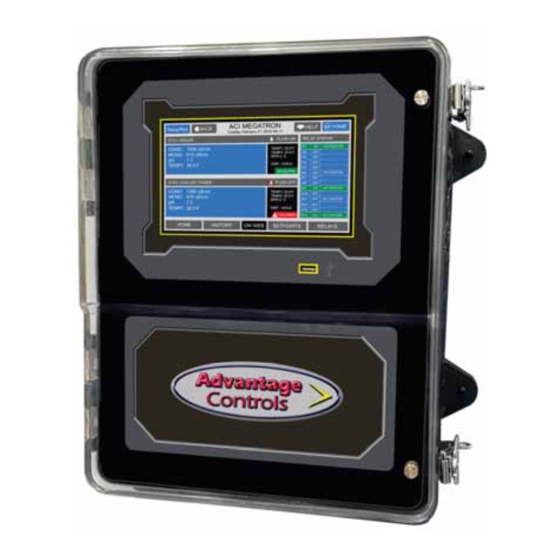
Consult representative for more details. Description of Unit MegaTronMT controllers can control single or multiple recirculating water systems, including cooling tower and boiler applications, and may have various features depending on the model number. -
Page 4: Installation
Chemical Feed Timers Chemical feed timers are designed to automate the addition of various chemicals by activating a relay output. Multiple timers can be supplied depending upon the model number and each timer will include a relay output. All timers can be programmed to be one of the following types. Pulse Time - Accepts pulses from a make-up water meter (supplied separately). -
Page 5: Wiring Diagrams
Pre-Wired Pre-wired units are supplied with a 16 AWG cable(s) with 3-wire grounded USA 115 volt plug for incoming power and 3-wire grounded receptacle cords for all control relay outputs also 16 AWG. Conduit Conduit units are predrilled at the factory and supplied with conduit knockouts for easy hard wiring to supplied detachable connectors on the relay card(s) located in the lower section of the controller. - Page 6 Back Pane Connections MegaTronMT Back Pane Card Slots (H11, H12) Comm. Jumper Block Spare Power +12 VDC for paddlewheel flowmeters Relay Card Outputs 11-15 16-20 6-10 Incoming Power System Card Connections Standard System Card White White Note: Conductivity probe’s wire colors...
- Page 7 4-20mA Output Card Wiring For isolated 4-20mA outputs an external power source for the loop must be supplied. JP4 and JP5 on the board must be jumpered for isolated with an external power source supplied to the external VDC input. The external power source must not exceed 24 volts DC.
-
Page 8: Mounting Instructions
Mounting Instructions Select a mounting location that provides the operator easy access to the unit and a clear view of the controls through the cover of the controller. The location should be convenient to grounded electrical connections, the needed sample line plumbing, and should be on a stable vertical surface. WARNING: Avoid locations that expose the controller to direct sunlight, vapors, vibration, liquid spills or extreme temperatures;... - Page 9 Typical Cooling Tower Installation Diagram COOLING TOWER BLOWDOWN BLEED VALVE MAKE-UP TO DRAIN WATERMETER PUMP CIRCULATION CHILLER Cooling Tower Probe Assembly FS-FC TFS-C FS-0C TFS-OC 1A9A000262 E-30-PH pH Probe PE-21 FS-T -or- OE-21 ORP Probe PE-NUT FS-B1-SP 2C0A-150 FS-PT-P E-30-PH Paddle Flow Switch used with option FS-SP...
-
Page 10: Boiler
Boiler Standard boiler electrodes have a MNPT stainless steel bushing and are supplied with a FNPT cross & hold). For a successful installation, it is critical to observe the recommended distances and pipe sizes provided in the installation drawings. the electrode is exposed to water and not steam. Properly installed and adjusted, this device will prevent NOTES: Install a fully ported type valve between the electrode and the boiler. - Page 11 Boiler Conductivity Electrodes Fully ported gate or ball valve Throttling device 1" Continuous blow down line Electrode within a 1" cross with electrical 1/2" pipe connection vented Electrically between probe actuated and throttle blow down device and valve flush valve Warning - Do not use on bottom blowdown lines, only continuous or surface blowdown lines.
-
Page 12: Front Panel
III. Front Panel Description SET UP/RUN - System initializes into RUN mode. Press this key to put the controller in SET UP Mode and see HOME menu page. HOME - Used to go back to the HOME menu page. HELP - Used to access help screens. -
Page 13: System Operation Overview
Calibration All MegaTronMT controllers are factory calibrated for temperature, conductivity, pH and ORP. All units are shipped with the date preset, and the clock set to your current time. These readings and settings should be 1. -
Page 14: Menu Navigation
V. Menu Navigation To access the menus press the Set Up / Run key on the front panel. This takes you to the Home menu. box on the screen. Once you have stepped through the sub menus to reach a point at which a value or selection is made a Pop-up window will appear prompting you to enter a desired value or selection. - Page 15 Set Point Options SET POINT - What reading turns the relay on DIFFERENTIAL - Amount reading changes by before HIGH ALARM - What reading generates a High alarm. LOW ALARM - What reading generates a Low alarm. LIMIT TIME - What amount of continuous bleeding will generate a time alarm notice.
- Page 16 2.4. Boiler Conductivity the conductivity sampling method. Timed sampling incorporates a sample timer which allows the boiler to be sampled at periodic intervals. Sample intervals are adjustable from 1 minute to 99 hours, 59 min. Sample duration (on-time) is adjustable from 1 second to 99 minutes, 59 seconds.
- Page 17 2.6. Calibration Calibration is for adjusting the displayed value of a probes reading to match your tester or known solution. CALIBRATION - For adjusting the actual reading values of the available analog probe inputs, such as conductivity, pH, ORP or temperature. 2.6.a.
- Page 18 2.7. Timers A unit may have up to 5 selectable timers for each system on a controller. All timers are associated with their system, so for a % of post bleed timer looks at the bleed of that system. TIMERS - Select the type (28-day, pulse, limit, percent or percent of post blowdown) as well as the run times of each timer available per system.
- Page 19 2.7.d. Recycle Timer ON CYCLE timer is to be on. OFF CYCLE - The amount of time that the cycle will ON/OFF TIMER - This is the displayed count down of time for the cycle the timer is in. 2.7.e. Post Bleed Timer % of SOURCE - The % of the post bleed time or other source time that you want the timer to run.
- Page 20 2.7.g. 28-Day Timer Each 28-day timer has Program 1-4 for programming the various feed times. While the programming steps WEEKS - The week(s) that the timer is to feed. DAYS - The day(s) that the timer is to feed. START - The time of day for the timer to start. RUN - How long the timer is to run.
- Page 21 2.9. Water Meters / Totalizers Each system with a timer on it will have 2 water meter inputs. Each of these can have the incoming contact loss by subtracting the deference between a systems 2 water meter inputs. CONTACT VALUE contact;...
- Page 22 3.1. 4-20mA Out Units with a 4-20mA output option will have a menu for setting up the 4-20mA output. The 4mA and 20mA of 8.0. SIGNAL SOURCE - Select which probe reading the mA will use as its reading source. 4 mA VALUE - What the 4mA signal equals 20mA VALUE - What the 20mA signal equals on the assigned signal sources scale.
- Page 23 While in the High or Low calibration pop-up screen use the up and down arrows to change the output value being read with the volt meter. Adjust the High value for the 20 mA reading and the Low value for the 4 mA value.
- Page 24 Customize RUN SCREEN - Allows the user to select what will be shown on the screen while the controller is in the RUN mode. Like diplaying temperature readings, water meter totals for a particular system or the conductivity units of measure. NOTE: When entering values for custom names use the numerical keys for numbers and the up / down arrows to scroll through all the characters of a key...
- Page 25 Run Screen This lets you customize various aspects of the RUN screen. MAIN SCREEN - Customize what is displayed on the RUN screen. SCREENS SHOWN - Pick if the mA input & Aux Flow screens are scrolled. CYCLE TIME - The amount of time between screen scrolls.
- Page 26 Date and Time Set Up DATE AND TIME - For setting the date, time, day and week on the controller. Relays CONFIGURE RELAYS - This menu lets you choose a Main Action or function (timer 1, conductivity, alarms etc...) to activates a relay. A pop-up screen appears with a list of all available activation functions to arrow through.
- Page 27 Flow Switch Temperature Scale This menu is used to select the type of temperature scale to display. Network The Network menu is used when a controller is being remotely communicated with either a local network connection or over the internet on the Web Advantage server. IP Address, IP Mask, Gateway, and other information can be viwed from this menu.
- Page 28 Viewing History RELAY LOGS - Relay activations displayed in a log form. Arrow up to advance through the log. ALARM LOG - Alarm activations in log form. SENSOR HISTORY - For selecting the parameters graph form. EVENT LOG - Displays various activities. Notepad Entries The Notepad section under History is where the user goes to enter new values for the customized notepad...
- Page 29 Flow Meter Setup of the current settings. PULSE VALUE contact, i.e. 225. UNITS i.e. Pulses / Ounce. RESET TOTAL - Resets the totalized count of the meter. VERIFY ALARM - relay the controller will give an alarm if it does not receive a contact or pulse from the aux meter within the amount of RELAY LINK - The relay link informs the particular aux meter input is relevant to the control function that the should be linked to the relay that is driven by the feed timer that pump will be controlled by.
- Page 30 In the STATUS view the accumulated ON time is shown along with the main activator, custom name and current status: action...
-
Page 31: Maintenance
VI. Maintenance The only required maintenance for normal uninterrupted operation of your MegaTronMT controller is cleaning of the electrode(s). After initial start up, it is a good idea to clean the electrode frequently until a schedule To determine the required cleaning frequency, record the reading on the controller before the electrode is removed for cleaning. -
Page 32: Troubleshooting
VII. Troubleshooting The MegaTronMT controller is designed for many years of trouble free operation. Should a problem occur, refer to the following chart to help identify the problem. If replacement is required, follow the procedures listed in the Warranty and Factory Service portion of this manual. -
Page 33: Warranty & 30 Day Billing Memo Policy
VIII. Advantage Controls’ Product Warranty Advantage Controls warrants control systems of its manufacture to be free of defects in material or workmanship. Liability under this policy extends for 24 months from date of installation. Liability is limited to repair or replacement of any failed equipment or part proven defective in material or workmanship... -
Page 34: Additional Wiring Diagrams
Common boiler blowdown valve connections. N.C. N.O. COM (1 - WHITE) N.O. (2 - BLACK) GND ( - GREEN) SOLENOID VALVE (TOP VIEW) MBWB 1036 MOTORIZED BALL VALVE (SIDE VIEW) MBWA 1075 BLOWDOWN VALVE (TOP VIEW) Card Slots (H11, H12) Comm. - Page 35 Pyxis Fluorometer Wiring for Card Slots MegaTron MT (H11, H12) Comm. Note: Refer to Jumper Block full manual for additional information Spare Power Cable Relay Card Outputs 11-15 16-20 6-10 Input 1 - Incoming Power Input 1 + GREEN (-4-20) WHITE (+4-20) NOTE: Pyxis may replace the WHITE wire with a BROWN wire...
- Page 36 CABLE-7P-2A Wiring a Nano-M to a MegaTronMT, or *Other Building Management System Note: Refer to full manual for Card Slots (H11, H12) additional information Comm. Jumper Block Spare Power Incoming Power Cable Relay Card Outputs 11-15 16-20 6-10 BLACK (ground)
- Page 37 - Notes -...
- Page 40 Get the Advantage in Water Treatment Equipment Advantage Controls can give you the Advantage in products, knowledge and support on all of your water treatment equipment needs. Cooling Tower Controllers Boiler Blow Down Controllers Blow Down Valve Packages Solenoid Valves...
Need help?
Do you have a question about the MegaTronMT and is the answer not in the manual?
Questions and answers