Table of Contents
Advertisement
Quick Links
Advertisement
Table of Contents

Related Manuals for Advantage Controls MegaTron Series


Summary of Contents for Advantage Controls MegaTron Series
- Page 1 MegaTron Controller Manual Installation Maintenance HE-30 8/26/2002...
-
Page 2: Table Of Contents
MegaTron Combination Controller Instruction & Maintenance Manual Table of Contents Contents Page No. Introduction ............... 3 Model Numbering.............. 3 Description of Unit............. 3 Installation………………………………………………………5 Electrical Wiring ..............5 Wiring Diagrams………………………………………………6 Mounting Instructions ............7 Electrode Installation ............7 Cooling Tower............8 Boiler................ -
Page 3: Introduction
Introduction The MegaTron microprocessor based controllers are designed to provide a wide range of control functions for recirculating water treatment systems. The controller is programmed through a front panel keypad and can be configured to provide a customized control system for your application. Your particular unit’s functions can be determined be comparing the units model number to the Model Numbering Table (see page 3). - Page 4 may be feature differences between the two systems on a unit with two systems. (See model numbering table on page 3.) Control Functions Each of these control functions are based on an analog input from a probe and will include user settable relay control settings along with a High and Low Alarm setting and Limit Timer.
-
Page 5: Installation
Installation Electrical Wiring The MegaTron controller has an internal regulated fused power supply that will operate off of 90 to 250 VAC at 47 to 63 Hz on the incoming wiring. Each output relay is individually protected with a replaceable fuse. Relay outputs will equal incoming line voltage. -
Page 6: Wiring Diagrams
Relay Card Diagram System Card Wiring Units are provided with all low signal wires (probe, water meter, flow …) pre-wired with labeled cables coming out of the controller. If it is desirable to wire directly to the system cards the following diagram indicates all connection for each system card. ☼... -
Page 7: Mounting Instructions
Mounting Instructions Select a mounting location that provides the operator easy access to the unit and a clear view of the controls through the cover of the controller. The location should be convenient to grounded electrical connections, the needed sample line plumbing and is on a stable vertical surface. -
Page 8: Cooling Tower
pH and/or Conductivity Probe ORP Probe TE-4A PE-2 or OE-2 Typical Cooling Tower Installation Diagram Boiler Standard boiler electrodes (part # BE-4BC) have a 1” MNPT stainless steel bushing and are supplied with a 1”FNPT cross designed for mounting in the skimmer (surface) blowdown line. - Page 9 successful installation, it is critical to observe the recommended distances and pipe sizes provided in the installation drawings. The probes are temperature compensated for increased accuracy. For best results, the electrode cross should be mounted on a 1"skimmer blowdown line within 4' of the boiler.
- Page 10 Typical Continuous Sampling Boiler Installation Diagram Typical Timed Sampling and Sample and Hold Boiler Installation...
-
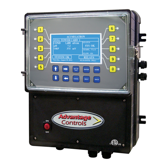
Page 11: Front Panel Drawing
Front Panel Description NUMBER Keys- Used to enter new values in the SET UP mode and to access desired sub menus. UP/DOWN - Used to cycle through text options to find desired setting. LEFT/RIGHT - Used to cycle through text or setting options to find desired setting. -
Page 12: System Operation Overview
IV. System Operation Overview Operation MegaTron controllers have two modes of operation, RUN and SET-UP. RUN - This mode is for normal operation. In the RUN mode the display will show each system's parameters. If an alarm is present the ALARM box will flash how many alarms are present. -
Page 13: Menu Navigation
match, key in the correct ORP value, and push ENTER. Press the SETUP/RUN key to resume normal operation. There are limits to how much the calibration can be adjusted. The instrument will only accept new conductivity values which are from 1/2 to 2x the present reading. Any entry outside this range will cause a default to the original reading. - Page 14 Set Points The same basic format is used for defining each available analog probe input’s control parameters. Boiler conductivity systems will also have an additional menu step for programming the sampling method desired from continuous, timed or sample and hold. SET POINTS –...
- Page 15 pH and ORP Calibration >SYSTEM 1 pH CALIBRATION< 1 POINT – With a clean probe on-line seeing the 1 POINT CAL system’s water enter the known (tested from a calibrated hand held tester) value. 2 POINT CAL 2 POINT – Enter a known Low value with a clean probe in a buffer solution.
- Page 16 Pulse Timer PULSES- The number of contacts from water >SYSTEM 1 TIMER 1 CHANGE< meter to count be activating timer. The amount of timer for the timer RUN TIME- PULSES to run RUN TIME Since each system with METER INPUT- METER INPUT timers has two water meter inputs you must select which meter to get contacts from.
- Page 17 28-Day Timer Each 28-day timer has a Program 1 and a Program 2 for programming the various feed times. The programming for Program 1 and 2 are the same but allow for more variation in the timer’s relay activation. >SYSTEM 1 TIMER 1 CHANGE< WEEKS- The week(s) that the timer is to feed.
- Page 18 Configure Provides access to menus to set-up passwords, relay activation, temp scale, display contrast, flow switch, inputs, history time stamps, factory set-up and system information. INPUTS- This screen shows what digital >CONFIGURE< inputs are available on the unit such as water PASSWORD CONTRAST meters, flow and drum level alarms.
- Page 19 History The onboard history allows for viewing the history of the probe readings, relay activations, key pad activity, calibrations and alarm logs for each system present. An initial overview page is displayed showing your current sample interval, the calculated number of days the unit can keep probe history for before loosing the oldest.
-
Page 20: Maintenance
VI. Maintenance The only required maintenance for normal uninterrupted operation of your MegaTron controller is cleaning of the electrode(s). After initial start up, it is a good idea to clean the electrode frequently until a schedule based on need has been developed. Since each application is unique, it is difficult to estimate the required frequency of cleaning. - Page 21 2. Spray with water and/or detergent, using a soft brush to dislodge any particulate matter. 3. Visually inspect the electrode for signs of damage. 4. Calibrate the electrode. 5. Replace the PTFE tape and re-mount into the system, taking care to avoid torsion on the cable.
-
Page 22: Troubleshooting
VII. Troubleshooting The Advantage MegaTron controller is designed for many years of trouble free operation. Should a problem occur, refer to the following chart to help identify the problem. If replacement is required, follow the procedures listed in the Warranty and Factory Service portion of this manual. -
Page 23: Warranty & 30 Day Billing Memo Policy
VIII. Advantage Controls’ Product Warranty Advantage Controls, Inc. warrants control systems of its manufacture to be free of defects in material or workmanship. Liability under this policy extends for 24 months from date of installation. Liability is limited to repair or replacement of any failed equipment or part proven defective in material or workmanship upon manufacturer’s...
Need help?
Do you have a question about the MegaTron Series and is the answer not in the manual?
Questions and answers