Table of Contents

Subscribe to Our Youtube Channel
Related Manuals for Advantage Controls MicroTron


Summary of Contents for Advantage Controls MicroTron
- Page 1 Manual MicroTron Tower Controller Installation Maintenance Repair Manual Advantage Controls 4700 Harold Abitz Dr. Muskogee, OK 74403 Phone: 918-686-6211 Fax: 888-686-6211 www.advantagecontrols.com 04/19 email: support@advantagecontrols.com...
-
Page 2: Table Of Contents
VIII. Warranty & 30 Day Billing Memo Policy ........23 Instructions herein apply to all MicroTron tower controllers. Additional options described in this manual may or may not be present on your unit. Refer to Model Numbering on Page 3. -
Page 3: Introduction
Model Numbering MicroTron controllers have several base functions and optional features available. Your unit may be supplied with one or more of the options that are described in this manual. To determine what features apply to your unit, check the model number label located on the controller enclosure. -
Page 4: Description Of Unit
Description Control Functions Each of the control functions is based on an analog input from a probe and will include user settable relay control settings along with a High and Low Alarm setting and Limit Timer. Each control function will include a control relay output. -
Page 5: Installation
III. Installation Electrical Wiring The standard MicroTron Tower controller has an internal regulated power supply that will operate in the range of approximately 100 to 240 VAC on the incoming wiring. Output relay(s) are protected with a replaceable fuse. Each relay’s output voltage will equal incoming line voltage. Prewired units are supplied with a 16 AWG cable with 3-wire grounded USA 115 volt plug for incoming power and 18 AWG 3-wire grounded U.S.A. -
Page 6: Conduit Layout For Lcd Display
Conduit Layout for LCD Display Logic Board Relay / Power Board (Rev. D) Rev. D 5A (R2) 5A (R4) Level Wand Pulse 1 Contrast Ribbon Cable POWER INPUT Test Serial Line TP-8 Pulse 2 Level 2 Connection TP-6 Pulse 3 Level 3 Test TP-10... -
Page 7: Electrode Installation
Electrode Installation MicroTron tower controllers may come configured for various recirculating water systems. Listed below are instructions for typical cooling tower installations. Your specific installation requirements may differ but should conform to these instructions as much as possible for proper operation. The standard probe(s) and/or flow assembly for cooling tower installations is constructed of schedule 80 PVC and supplied with ¾” slip fittings for installing into a sample line. To insure proper operation the sample line must have a flow rate of 3-10 gpm. Inlet pressure must be higher than outlet pressure in order for water to flow past the electrode(s) at the required rate. The probes are temperature compensated for increased accuracy. NOTES: Install an isolation valve on either side of the flow assembly so electrodes can be easily isolated for removal and cleaning. -
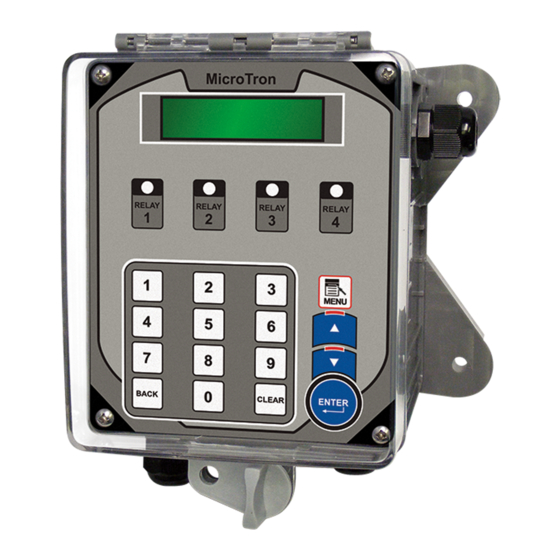
Page 8: Front Panel Description
Front Panel Description READ: 1x16 (1/4”) Alpha Numeric Display. CONTROL: Relay 1, Relay 2, Relay 3, Relay 4 - HOA switches for control relays. SET UP SET UP/RUN key - System initializes into RUN mode. Press this switch to toggle the controller from SET UP mode to RUN mode. -
Page 9: System Operation Overview
System Operation Overview MicroTron controllers have two modes of operation, RUN and SET UP. Both the RUN and SET UP menus are circular. Pressing the DOWN key in either menu will display the next line of information on the display. -
Page 10: Calibration
CALIBRATION -- CALIBRATION -- All MicroTron controllers are factory calibrated for CALIBRATE xxxoF temperature, conductivity, pH and/or ORP (if present). ENTER These values should be verified for accuracy, and adjusted as per the instructions listed below and to the To change temperature CLEAR side. - Page 11 This menu is used to set bleed control parameters -- CALIBRATION -- including set point, differential, high and low alarms BLEED TRIP XXXX plus a feed limit timer. ENTER BleedTrip - A reading above this value will activate the To change bleed trip point CLEAR blowdown relay until the reading falls by the amount of the differential below the trip point.
-
Page 12: Ph Feed Set
This menu is used to set pH control parameters -- PH FEED SET -- including set point, differential, high and low alarms PH TRIP XXX plus a feed limit timer. (This menu choice will be ENTER present only if you have the pH control option, see model numbering on page 3.) To change pH trip point CLEAR... -
Page 13: Orp Feed Set
This menu is used to set ORP control parameters -- ORP FEED SET -- including set point, differential, high and low alarms ORP TRIP XXX plus a feed limit timer. (This menu choice will be ENTER present only if you have the ORP control option, see model numbering on page 3.) To change trip point CLEAR... -
Page 14: Chem Feed Set
-- CHEM FEED SET -- Units with selectable feed timer(s) will have this SET Shows timer currently selected UP menu for selecting the chemical feed method ENTER and setting the feed time. A selectable feed timer can be programmed to be one of the following: To change to a different timer ENTER 1. -
Page 15: Biocide Set
-- BIOCIDE SET -- Units with a biocide timer will have this SET UP menu Shows BIO A timer 1 activation day for setting biocide feed times. Biocide Set Menu ENTER consists of two weekdays, week and start times, one feed length time and an overall prebleed and lockout To change day of the week ENTER... -
Page 16: Clock Set
-- CLOCK SET -- The CLOCK SET menu is for adjusting the time, date SET TIME XX.XX.XX (hh.mm.ss) and day of the week. ENTER After entering a new value, hit the ENTER key to To change clock setting CLEAR accept the value and advance. To accept value keyed in The clock time is based on a 24 hour clock. -
Page 17: System Menu Set
-- SYSTEM SET -- This menu is used to configure the controller to specific PASSWORD XXXX operational needs. All of the items in this menu may not apply depending on the controller model but will always be present. Numeric keys to set ENTER password NOTE: Do not use this menu to make calibration adjustments. -
Page 18: Diagnostics Menu
SYSTEM SET (continued) FLOW ALARM - With FLOW ALARM ON when FLOW WHEN CLOSED the system loses flow, an alarm signal can be sent. FLOW ALARM OFF means that no alarm signal is Flow When Open ENTER sent in the event of loss of system flow. CONCURRENT - Only applies if there are two or FLOW ALARM ON more feed timers. -
Page 19: Run Menu
-- SYSTEM SET -- This menu is used to select, enter and test the MODEL # LCFB-2 following items. MODEL NUMBER - Read only screen. FIRMWARE V.(n) SOFTWARE VERSION NUMBER - Read only screen. Please have this number should you need to TEST DISPLAY contact customer service. -
Page 20: Maintenance
During normal operations the controller will be in the RUN mode where current values are displayed. If left in the SET UP mode the display will revert to the RUN mode screen if no keys are touched for 3 minutes. If an alarm is present it will be flashed on the screen in the RUN mode. -
Page 21: Troubleshooting
The only required maintenance for normal uninterrupted operation of your MicroTron controller is cleaning of the electrode(s). After initial start up, it is a good idea to clean the electrode(s) frequently until a schedule based on need has een developed. Since each application is unique, it is difficult to estimate the required frequency of cleaning. o determine the required cleaning frequency, record the reading on the controller before the electrode is removed for cleaning. After cleaning, record the new reading. If a change is observed in the two readings, the electrode was dirty. The more significant the change, the dirtier the electrode. If no change occurs, cleaning... - Page 22 The Advantage Microtron controller is designed for many years of trouble free operation. Should a problem occur, refer to the following chart to help identify the problem. SYMPTOM POSSIBLE CAUSE SOLUTION False reading Bad or dirty electrode Clean as needed...
-
Page 23: Warranty & 30 Day Billing Memo Policy
VIII. Advantage Controls’ Product Warranty Advantage Controls warrants control systems of its manufacture to be free of defects in material or workmanship. Liability under this policy extends for 24 months from date of installation. Liability is limited to repair or replacement of any failed equipment or part proven defective in material or workmanship upon manufacturer’s... - Page 24 Get the Advantage in Water Treatment Equipment Advantage Controls can give you the Advantage in products, knowledge and support on all of your water treatment equipment needs. Cooling Tower Controllers Boiler Blow Down Controllers Blow Down Valve Packages Solenoid Valves Water Meters Chemical Metering Pumps Corrosion Coupon Racks...
Need help?
Do you have a question about the MicroTron and is the answer not in the manual?
Questions and answers