Table of Contents
Advertisement
Quick Links
Advertisement
Table of Contents

Subscribe to Our Youtube Channel
Related Manuals for Advantage Controls MegaTronMR


Summary of Contents for Advantage Controls MegaTronMR
- Page 1 T ouc h Manual Touch Screen Controller Installation Maintenance Repair Manual Advantage Controls 4700 Harold-Abitz Dr. Muskogee, OK 74403 Phone: 800-743-7431 Fax: 888-686-6212 www.advantagecontrols.com 9/2024 E-mail: support@advantagecontrols.com...
-
Page 2: Table Of Contents
MegaTronMR Touch Screen Controller Instruction & Maintenance Manual Table of Contents Contents Page Introduction ................. 3 Model Numbering ............... 3 Installation .................. 4 Electrical Wiring ................4 Box Layout Overview..............5 Wiring Diagrams ................. 5 A. Relay Card Wiring ..............5 B. -
Page 3: Introduction
Model Numbering table listed below. MegaTronMR units have several base system control functions and unit optional features. Your unit may be supplied with one or more of the features described in this manual. To determine what features apply to your unit check the model number label located on the controller enclosure. -
Page 4: Installation
Installation Electrical Wiring The MegaTron MR controller has an internal regulated fused power supply that will operate off of 90 to 250 VAC at 47 to 63 Hz on the incoming wiring. Each output relay is individually protected with a replaceable 2.5 amp fuse. -
Page 5: Box Layout Overview
Box Layout Overview Carrier Board for RO System, mA and BMS cards RO Card mA Card Auxilary Flow Meter Inputs Logic Board Relay Relay Board Power Supply Board Relay Relay Relay Relay Wiring Diagrams Relay Card Wiring System Card Wiring RO System Card Rev. -
Page 6: Adding Ph/Orp Bnc Wiring
Adding pH/ORP BNC Wiring RO System Card Green Inlet Conductivity White Temperature Note: Conductivity probe’s wire colors Black may vary. If so, Green match based on Permeate Conductivity White cond and temp. BNC wires Temperature Black Black Black Single green solution reference wire Ground for pH/ORP... -
Page 7: 4-20Ma Output Card Wiring
4-20mA Output Card Wiring Isolated Configuration For isolated 4-20mA outputs an external power source for the loop must be supplied. JP4 and JP5 on the board must be jumpered for isolated, with an external power source supplied to the external VDC input. The external power source must not exceed 24 volts DC. -
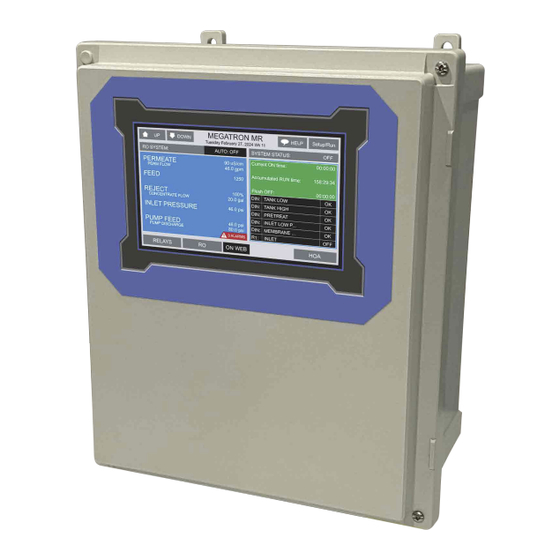
Page 8: Front Panel
III. Front Panel Description SET UP/RUN - System initializes into RUN mode. Press this key to put the controller in SET UP Mode and see HOME menu page. HOME - Used to go back to the HOME menu page. HELP - Used to access help screens. -
Page 9: System Operation Overview
Calibration All MegaTronMR controllers are factory calibrated for temperature, conductivity, pH, and ORP. All units are shipped with the date preset, and the clock set to your current time. These readings and settings should be verified for accuracy, and adjusted as per the instructions listed below. -
Page 10: Menu Navigation
To access the menus, press the Set Up / Run key on the front panel. This takes you to the Home menu. MegaTronMR controller’s menus are easily navigated by pressing the associated number key next to a menu box on the screen. Once you have stepped through the sub menus to reach a point at which a value or selection is made, a Pop-up window will appear prompting you to enter a desired value or selection. - Page 11 Set Point Options SET POINT - What reading turns the relay on. DIFFERENTIAL - Amount reading changes by before the relay is turned off HIGH ALARM - What reading generates a High alarm. LOW ALARM - What reading generates a Low alarm. LIMIT TIME - What amount of continuous bleeding will generate a time alarm notice.
- Page 12 1.2.1. RO Activators and Shut-Offs RO ACTIVATOR 1-3 - Defines what will activate the RO like a low tank level or other input. Multiple things can activate the RO but typically only Activator 1 is needed. STARTUP TIME - The amount of time the inlet valve must be open before the RO pump relay is activated.
- Page 13 FLUSH METHOD -Define the flush type. FLUSH TRIGGER- Define the input to use. FLUSH DURATION - The amount of time for this flush. 1.2.4. RO Run Timers RO ACCUMULATE RUN TIMER - Settings for the amount of accumulated RO run limit time and alarming. RO OFF TIMER- Alarm settings for consecutive amount of timer the RO has not ran.
- Page 14 LIMIT TIME - Setting for an individual or consecutive number of on or run hours to trigger an alarm. ALARM NOTIFY - Select if the alarm is to be displayed, send remote notification or not. 1.3. pH and ORP The pH and ORP set point settings follow the same format as shown above in section 1.1. INTERRUPT - Only applies to pH settings and allows the Interruption of pH control during bleed, other chemical feed, or both.
- Page 15 1.5. Calibration Calibration is for adjusting the displayed value of a probes reading to match your tester or known solution. Pick the system or mA input first. From a particular system, pick the probe to calibrate. CALIBRATION - For adjusting the actual reading values of the available analog probe inputs, such as conductivity, pH, ORP or temperature.
- Page 16 1.6. Chem Feed A unit may have up to 4 selectable timers for each system on a controller. All timers are associated with their system. CHEM FEED - Select the type (28-Day, pulse, percent, recycle), as well as the run times of each timer available per system.
- Page 17 1.6.3. Pulse Timer ACCUMULATE - The number of gallons or liters from water meter to count before activating timer. RUN TIME - The amount of time for the timer to run METER INPUT - Select water meter 1 or 2 for the timer’s activation.
- Page 18 1.7. Alarms ALARMS - Shows any current alarms. Accessible from the Setup/Run screen. 1.8. Water Meters / Totalizers Each system will have 2 water meter inputs. Each of these can have the incoming contact defined and track the water usage. A volume alarm can also be defined.. CONTACT VALUE - Defines the numerical value for a contact;...
- Page 19 mA Signals mA OUT SETTINGS - Selecting source and range of outputs. mA IN SETTINGS - Setting control and alarms for inputs mA OUT CALIBRATION - Calibrating outputs. mA IN CALIBRATION - Calibrating inputs and displayed range. 2.1. 4-20mA Out Settings Units with a 4-20mA output option will have a menu for setting up the 4-20mA output.
- Page 20 4-20mA Output Calibration 4-20mA outputs can be calibrated to ensure that the output generated by the controller and received by the external device match. With a voltmeter connected across the out and return wires (see page 6) of the 4-20mA output channel, to be calibrated, go into the output’s Low or High calibration.
- Page 21 The 20mA and 4mA values are where the controller’s raw analog to digital value is adjusted to match a 20mA (full scale) and 4mA (bottom of scale) signal from the external device inputting the 4-20mA input. The external device must be connected to the controller and showing either full or bottom of scale when calibrating each.
- Page 22 Notepad The Notepad function allows the user to set up and store manually entered data or perform simple calculations between two differernt sensor or notepad inputs. There are ten notepad fields per system card and each can be given a custom name, UOM and number range. NAME - Pick from a list of defined names or customize your own or if you want the Notepad to be a Calculation.
- Page 23 mA Inputs NAME - Name the input. UNITS - Set the units of measurement. NUMBER - Set the number range. Run Screen This lets you customize various aspects of the RUN screen. MAIN SCREEN - Customize what is displayed on the RUN screen.
- Page 24 Password ADMIN PASSWORD - The administrator password gives access to all menus except factory set up. USER PASSWORD - The user password allows the user to access HOME menus that are made available in USER SET UP. USER SETUP - The user setup chooses which menus they can access.
- Page 25 History This menu is used to set the history “time stamp” interval, the water meter daily history starting hour, the alarm delay period and the USB history save format. INTERVAL - The amount of time between each history time stamp for probe readings. W/M HOUR - The time of day that the daily water meter history cycle is to start.
- Page 26 History The onboard history allows for viewing the history of the probe readings, relay activations, key-pad activity, calibrations, water meter hourly and daily logs, and alarms for each system present. It is also where Notepad data is entered and reviewed. An initial overview page is displayed showing your current sample interval, the calculated number of days the unit can keep probe history for before losing the oldest.
- Page 27 Flow Meters A unit may have up to 5 option auxiliary flow meter inputs. These additional inputs are for tracking various flow meter devices. They can also be linked to a system’s water meter input for additional tracking and alarm capabilities.
- Page 28 Relays STATUS - Allows for viewing accumulated relay ON times, temporary forcing relays ON or OFF or seeing which relay is on. RESET - Allows the accumulated run time of a particular relay to be reset to zero. FORCE - Allows a relay to be manually forced ON or OFF for a single event from 0-999 minutes.
-
Page 29: Maintenance
VI. Maintenance The only required maintenance for normal uninterrupted operation of your MegaTron MR controller is cleaning of the electrode(s). After initial startup, it is a good idea to clean the electrode frequently until a schedule based on need has been developed. Since each application is unique, it is difficult to estimate the required frequency of cleaning. -
Page 30: Warranty & 30 Day Billing Memo Policy
VII. Advantage Controls’ Product Warranty Advantage Controls warrants control systems of its manufacture to be free of defects in material or workmanship. Liability under this policy extends for 24 months from the date of installation. Liability is limited to repair or replacement of any failed equipment or part proven defective in material or workmanship upon manufacturer’s examination. -
Page 31: Related Items
VIII. Related Items CHIP RO Controller CHIP Manual ROC-2HE RO Controller ROC-2HE Manual ROC-3HE RO Controller ROC-3HE Manual ROC-5 RO Controller ROC-5 Manual... - Page 32 Get the Advantage in Water Treatment Equipment Advantage Controls can give you the Advantage in products, knowledge, and support for all of your water treatment equipment needs. Cooling Tower Controllers Boiler Blow Down Controllers Blow Down Valve Packages Solenoid Valves...
Need help?
Do you have a question about the MegaTronMR and is the answer not in the manual?
Questions and answers