Table of Contents

Subscribe to Our Youtube Channel
Related Manuals for Advantage Controls 200 Series


Summary of Contents for Advantage Controls 200 Series
- Page 1 Manual Series 200 Controller Installation Maintenance Repair Manual Advantage Controls 4700 Harold-Abitz Dr. Muskogee, OK 74403 Phone: 800-743-7431 Fax: 888-686-6212 www.advantagecontrols.com email: support@advantagecontrols.com 09/2020...
-
Page 2: Table Of Contents
Series 200 Controller Manual Table of Contents Contents Page Introduction ................3 Installation ..................4 Mounting ..................4 Power Wiring ................4 Wiring Diagrams ................5 I/O List ..................6 Switch Inputs ................7 III. System Operation ..............9 Operation ................9 Calibration ...............14 Control Functions ............14 Setpoints ..................15 Set Standard Setpoints ...........15 Differential Pressure Setpoints ........16 Conductivity Setpoints ............17... -
Page 3: Introduction
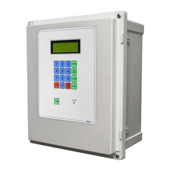
Introduction The Advantage Controls Series 200 RO controller is a state of the art control system for commercial and industrial reverse osmosis systems. The S200 combines features that have not previously been available in one compact unit. The S200 is a microprocessor-controlled system that can monitor multiple pressure sensors and/or pressure switches. -
Page 4: Installation
Installation Mounting Instructions Mount the S200 in a convenient location on the RO equipment using the four mounting ears provided with the unit or the optional panel mounting bracket. Power Wiring AC power for the controller can be S5-265VAC, 50/60Hz. AC power for the unit is connected to terminal strip P1. -
Page 5: Wiring Diagrams
Terminal Strips and Connectors NOTES: 1. High voltage wiring should not be run in the same conduit as sensor and control wiring. 2. The switch inputs are dry contact only. Connecting power to these inputs will damage the controller. 3. The supply voltage to the board is the voltage that is output from the relays. -
Page 6: I/O List
I/O List The following table is a list of the inputs and outputs on the main board. The list shows the reference name for each input or output, the description and the terminals strip number/ pin connections. Output Description Connection Inlet Valve P6, 4-6 RO Pump... -
Page 7: Switch Inputs
Valve Wiring Solenoid valves or motor valves can be operated by the controller. All valves must operate at the same voltage as the controller unless an external control relay is used. The inlet valve connects to NO and L2 of R1, terminals 4-5 of P6. If a motor valve is used, the common connection is connected to L2, the open connection connects to NO and the close connection connects to NC of R1, terminals 4-6 of P6. - Page 8 TDS / Conductivity Cell Wiring For accurate TDS / Conductivity readings, the cell should be installed in a tee fitting where a continuous flow of water passes over the cell and no air can be trapped around the cell. Refer to the figure below for example installation and page 5 for wiring. The feed cell is connected with 5 wires to terminal strip P16. The permeate cell is connected with 5 wires to terminal strip P17. Connect each colored wire to the terminal labeled with the same color.
-
Page 9: System Operation
III. System Operation Operation The S200 has 2 modes of operation: a standby mode and an operating mode. In the standby mode, the unit is effectively off. All output relays are turned off and the display shows STANDBY. In the operating mode, the unit operates automatically. All inputs are monitored and the outputs are controlled accordingly. Pressing the Power key will toggle the unit from standby to operate or from operate to standby. - Page 10 Tank Full The S200 can be operated with 1 or 2 level switches. With 1 level switch, the switch is connected to the tank full high input. When this switch has been active for the Tank Full Delay (107), the unit will shut down on tank full.
- Page 11 warning occurs, after the time programmed in this setpoint, the RO unit will shut down and the alarm will sound. The alarm can be cleared by pressing the Alarm Silence/Reset key twice. High Pressure Switch Alarm If the high pressure switch input becomes active for the the delay programmed in the Hi PSI Sw Delay (126), the unit will shutdown for a high pressure switch alarm.
- Page 12 Divert When the C2 limit is enabled and the C2 reading is above the limit, the divert relay will be activated. This will occur immediately with no delay. When the C2 reading drops below the limit, the divert relay will remain active for the time programmed in the Divert Delay(113) setpoint.
- Page 13 Flow Metering If the optional flow metering board is installed, up to 4 flow sensors can be monitored by the controller. The flow board is mounted on the main board. Each flow meter requires 3 connections: Power (+), signal (SIG) and ground (GND). For magnetic pickup sensors such as a Signet 515, the jumper for the meter should be in the B position. For sensors that require power, the jumper for the sensor should be moved to the A position. The K-Factor as supplied from the sensor manufacturer should be entered in the Span setpoint for each installed meter.
-
Page 14: Calibration
Refer to the figures on page 13 for the location of the terminal strips for connecting the sensors. The Terminal strips are 4 pin connections. The sensors connect to pins 2 and 3. The shield wire of the sensor connects to pin 3 and the signal wire connect to pin 2. To set a channel for pH, the 2 jumpers in the channel must be in the UPPER position. -
Page 15: Setpoints
Function 4 - CLOCK PROGRAMMING The clock time is programmed by pressing the Function key, 4 and then entering the current time, date and then pressing the Enter key. The time is entered in military format HHMM and the date is entered as MMDDYY. Function 5 - pH1 4 BUFFER/ ORP1 CALIBRATE If pH1 is enabled, Function 5 is used to calibrate the pH sensor to a pH 4 buffer. For further details, refer to the pH section of the manual. If ORP1 and ORP2 are enabled, Function 5 is used to calibrate the ORP1 sensor. -
Page 16: Differential Pressure Setpoints
SETPOINT DESCRIPTION RANGE DEFAULT 015 PS3 DELAY 0-999 PS3 WARNING/SHUTDOWN PS3 OFFSET 0-99 PS3 SPAN 0-9999 PS4 LO 0-9999 PS4 HI 0-9999 021 PS4 DELAY 0-999 PS4 WARNING/SHUTDOWN PS4 OFFSET 0-99 PS4 SPAN 0-9999 PS5 LO 0-9999 PS5 HI 0-9999 027 PS5 DELAY 0-999 PS5 WARNING/SHUTDOWN PS5 OFFSET... -
Page 17: Conductivity Setpoints
Conductivity Setpoints There are 5 setpoints for each conductivity input. The limit setpoint sets the value of the high conductivity alarm for the input. If set to 0000, the limit is disabled. When the limit is enabled, the delay setpoint is the time in seconds before a warning is generated. -
Page 18: Temperature Setpoints
SETPOINT DESCRIPTION RANGE DEFAULT FS2 LO LIMIT 0-9999 FS2 HI LIMIT 0-9999 062 FS2 DELAY 0-999 FS2 SPAN 0-999999 100000 FS3 LO LIMIT 0-9999 FS3 HI LIMIT 0-9999 066 FS3 DELAY 0-999 FS3 SPAN 0-999999 100000 FS4 LO LIMIT 0-9999 FS4 HI LIMIT 0-9999 070 FS4 DELAY... -
Page 19: Ph/Orp Setpoints
pH/ORP Setpoints SETPOINT DESCRIPTION RANGE DEFAULT pH/ORP SELECT - Enables display of the installed pH/ORP sensors. If set to 0, all displays are disabled. pH1 LO WARNING - Sets limit for pH1 low 0-14 warning. If set to 0, warning is disabled. pH1 HI WARNING - Sets limit for pH1 high 0-14 warning. -
Page 20: Misc. Setpoints
Misc. Setpoints SETPOINT DESCRIPTION RANGE DEFAULT 106 RO RELAY - When start signal is received 0-9999 sec. delay before RO pump starts. 107 TANK FULL DELAY - Delay before the RO 0-99 sec. shuts down due to a tank full condition. TANK FULL RESTART - Delay before RO 0-9999 sec. starts after a tank full condition clears. TANK FULL OVERRIDE - Time system will 0-9 min. - Page 21 SETPOINT DESCRIPTION RANGE DEFAULT FLUSH MODE - Determines the operation of the inlet valve and RO pump during flush. 123 FLUSH TIME - Length of flush cycle. 0-99 min. FLUSH INTERVAL - Selects the interval 0-99 hrs. between flushes when an interval type of flush is selected. 125 LO PSI DELAY - Delay before an active 0-99 sec. low pressure switch will cause a shutdown. 126 HI PSI SW DELAY - Delay before an active 0-99 sec. high pressure switch will cause a shutdown. AUX MODE - If set to 0, relay 4 operates as auxiliary pump control.If set to 1, relay 4 operates as a boost pump control.
-
Page 22: Warranty And Factory Service Policies
Manufacturer’s Product Warranty Advantage Controls warrants to the original purchaser that the products it manufactures will be free from defects in material and workmanship for a period of twelve months from the date of shipment on parts and ninety days on labor. Some non-Advantage manufactured resale items may have warranty periods less than twelve months. - Page 24 Get the Advantage in Water Treatment Equipment Advantage Controls can give you the Advantage in products, knowledge and support on all of your water treatment equipment needs. Cooling Tower Controllers Boiler Blow Down Controllers SET UP ENTER HOME Blow Down Valve Packages...
Need help?
Do you have a question about the 200 Series and is the answer not in the manual?
Questions and answers