Table of Contents

Subscribe to Our Youtube Channel
Related Manuals for Advantage Controls MINI-TROL IF


Summary of Contents for Advantage Controls MINI-TROL IF
- Page 1 Manual MINI-TROL IF Reverse Osmosis Controller Installation Maintenance Repair Manual Advantage Controls 4700 Harold-Abitz Dr. Muskogee, OK 74403 Phone: 800-743-7431 Fax: 888-686-6212 www.advantagecontrols.com 03/2021 email: support@advantagecontrols.com...
- Page 2 Installation 1. Confirm that the controller is configured for the proper voltage: 120, 240 or 24-volt. See ID label, as well as the label located on top of the transformer designating voltage. (See Fig. 1) 2. The RO pump motor or motor starter and the solenoid valves must be of the same voltage: 120, 240, or 24-volt. 3. Confirm that the (3) input signals – pressure switch, tank level switch, and pretreat switch – are all of the same configuration, normally open OR normally closed. 4. Confirm the desired jumper settings for your operation. The jumpers are factory set to Position B Auto Reset (disabled), Pressure Fault Retry (disabled), Tank Full restart time delay (2 seconds), Input contact type (NC, open to operate), and flush on tank full. If you wish to change any jumper functions, move that jumper to Position A. (See Table on next page.) 5. If a wire harness is provided with this controller, skip this section and proceed to Step 6. If wiring to the controller is required, proceed as follows: A. Remove the enclosure cover. B. Mark and drill necessary electrical entry holes in the empty enclosure. C. Terminate necessary wiring to the terminal strips as required. (See Fig. 1) Each terminal is labeled for the proper connection.
- Page 3 Figure 1 SELECTABLE JUMPERS J6 J5 J4 FLUSH RELAY RO PUMP RELAY K3 INLET RELAY CAUTION: REPLACE FUSES WITH SAME TYPE OR EQUIVALENT. JUMPER POSITION B POSITION A AUTO RESET DISABLED AUTO RESET ENABLED RETRIES DISABLED RETRIES ENABLED 2-SEC RESTART 15-MIN. RESTART N.O. SWITCHES N.C. SWITCHES TANK FULL FLUSH 24-HOUR FLUSH WARNING: All switch inputs must be dry contact only. If voltage is applied to these inputs, damage to the controller will result.
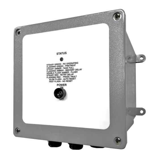
- Page 4 System Operation When the power switch it turned ON, the status LED will light Green, the inlet valve with OPEN and, after a 5-second delay, the RO pump will start. Under normal operation, the RO unit will run until: (A) the storage tank is full (status LED Amber) or (B) Pretreat lockout has occurred (status LED flashing Green). When A or B has cleared, after a time delay, the RO unit will restart, and the status LED will return to Green. Jumper setting J-6 selects a 2-second or 15-minute tank full restart time delay. Upon an alarm signal for Pressure Fault, the status LED will turn RED, the RO pump will stop, and the inlet valve will close. If jumper J-4 and J-5 are in Position B (disabled), the status LED will flash RED and the RO unit will not restart until the Power Switch has been manually cycled OFF and then ON to reset the unit. If jumper J-4 is in Position A (auto reset), every 60 minutes the controller will check the pressure fault and either stay OFF or START accordingly. If J-5 is in Position A (pressure fault retry), the RO unit will attempt to restart after 30 seconds, then 5 minutes, then 30 minutes. If the pressure alarm has not cleared after the third attempt, the RO unit will remain off until manually reset. If jumper J-4 and J-5 are in Position A, after a pressure fault condition, the RO unit will continually attempt to restart after each 60-minute cycle until the pressure switch input has cleared. If jumper J-8 is in Position A, the RO unit will flush every 24 hours of elapsed time. If jumper J-8 is in Position B, the RO unit will flush on tank full. During Flush, the inlet and flush valves are open and the RO pump is On. The flush time is 5 minutes. The status LED will double-flash AMBER. CAUTION 1. There are live circuits inside the controller even when the power switch on the front panel is in the OFF position.
- Page 5 Manufacturer’s Product Warranty Advantage Controls warrants units of its manufacture to be free of defects in material or workmanship. Liability under this policy extends for 24 months from date of installation. Liability is limited to repair or replacement of any failed equipment or part proven defective in material or workmanship upon manufacturer’s examination. Removal and installation costs are not included under this warranty. Manufacturer’s liability shall never exceed the selling price of equipment or part in question. Advantage disclaims all liability for damage caused by its products by improper installation, maintenance, use or attempts to operate products beyond their intended functionality, intentionally or otherwise, or any unauthorized repair. Advantage is not...
- Page 6 -Notes-...
- Page 7 Get the Advantage in Water Treatment Equipment Advantage Controls can give you the Advantage in products, knowledge and support on all of your water treatment equipment needs. Cooling Tower Controllers Boiler Blow Down Controllers SET UP ENTER HOME Blow Down Valve Packages HELP CANCEL BACK Solenoid Valves Water Meters Chemical Metering Pumps Corrosion Coupon Racks Chemical Solution Tanks Solid Feed Systems Feed Timers...
Need help?
Do you have a question about the MINI-TROL IF and is the answer not in the manual?
Questions and answers