
Subscribe to Our Youtube Channel
Related Manuals for Advantage Controls MegaTron


Summary of Contents for Advantage Controls MegaTron
- Page 1 Manual MegaTron Controller Installation Maintenance Repair Manual Advantage Controls P.O. Box 1472 Muskogee, OK 74402 Phone: 800-743-7431 Fax: 888-686-6212 www.advantagecontrols.com 03/2017 email: support@advantagecontrols.com...
-
Page 2: Table Of Contents
MegaTron Controller Instruction & Maintenance Manual Table of Contents Contents Page Introduction ................. 3 Model Numbering ............... 3 Description of Unit ..............3 Installation .................. 4 Electrical Wiring ................4 Wiring Diagrams ................. 5 Mounting Instructions ..............8 Electrode Installation ..............8 A. -
Page 3: Introduction
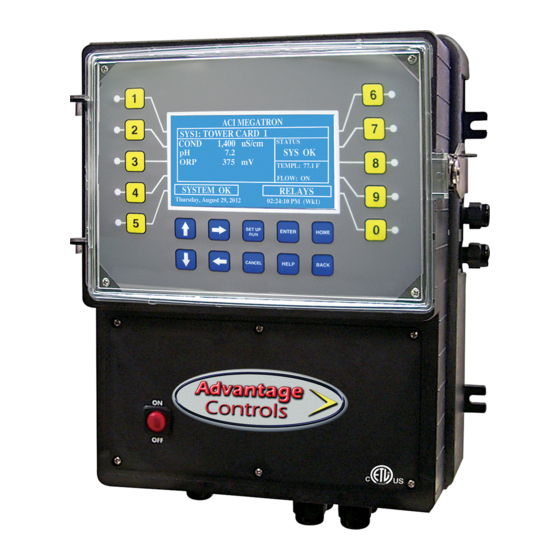
Introduction The MegaTron microprocessor based controllers are designed to provide a wide range of control functions for recirculating water treatment systems. The controller is programmed through a front panel keypad and can be configured to provide a customized control system for your application. Your particular unit’s functions can be determined by comparing the units model number to the Model Numbering table listed below. -
Page 4: Installation
Electrical Wiring The MegaTron controller has an internal regulated fused power supply that will operate off of 90 to 250 VAC at 47 to 63 Hz on the incoming wiring. Each output relay is individually protected with a replaceable fuse. -
Page 5: Wiring Diagrams
Pre-Wired Pre-wired units are supplied with a 16 AWG cable(s) with 3-wire grounded USA 115 volt plug for incoming power and 3-wire grounded receptacle cords for all control relay outputs also 16 AWG. NOTE: An additional male power cord is supplied with each group of 5 relays. All incoming power cords must be plugged in for the unit to work correctly. - Page 6 The communications card is always the first slot and system 1 card the second. The 4-20mA output card will be the slot after the last active system card and the 4-20mA input card 2 after the last system card. Ground Aux. 4 MegaTron Mother Board +5 VDC Aux. 3 Signal...
- Page 7 4-20mA Output Card Wiring Isolated Configuration For isolated 4-20mA outputs an external power source for the loop must be supplied. JP1 and JP2 on the board must not be jumpered when an external power source is being supplied. The external power source must not exceed 24 volts DC and will connect onto the card on connector J1 on the postion marked Loop Supply.
-
Page 8: Mounting Instructions
Electrode Installation MegaTron controllers may come configured for various circulating water systems. Listed below are instructions for cooling tower and boiler typical installations. Your specific installation requirements may differ but should conform to these instructions as much as possible for proper operation. - Page 9 Typical Cooling Tower Installation Diagram BLEED VALVE TO DRAIN Cooling Tower Probe Assembly FS-FC TFS-C FS-0C 1A9A000262 TFS-OC E-30-PH pH Probe PE-21 FS-T -or- OE-21 ORP Probe PE-NUT FS-B1-SP FS-PT-P 2C0A-150 E-30-PH Paddle Flow Switch used with option FS-SP Sample Valve Standard Tower Probes UNION-3/4TT Conductivity ....E-4A...
-
Page 10: Boiler
Boiler Standard boiler electrodes have a MNPT stainless steel bushing and are supplied with a FNPT cross designed for mounting in the skimmer (surface) blowdown line. Sampling of the boiler’s water can be achieved using one of two typical plumbing configurations (continuous sampling or timed and/or hold sampling). - Page 11 Boiler Conductivity Electrodes Fully ported gate or ball valve Throttling device SET UP HOME BACK CANCEL HELP 1" Continuous blow down line Advantage Controls, Inc. Electrode within a 1" cross with electrical 1/2" pipe connection vented Electrically between probe actuated and throttle blow down device and...
-
Page 12: Front Panel Drawing
III. Front Panel Description <HOME SETUP> SET POINTS DATE/TIME CALIBRATION CONFIGURE TIMERS HISTORY CUSTOMIZE WATER METER ALARMS RELAYS SET UP ENTER HOME CANCEL HELP BACK NUMBER Keys- Used to enter new values in the SET UP mode and to access desired sub menus. UP/DOWN - Used to cycle through text options to find desired setting. -
Page 13: System Operation Overview
Calibration All MegaTron controllers are factory calibrated for temperature, conductivity, pH and ORP. All units are shipped with the date preset, and the clock set to your current time. These readings and settings should be verified for accuracy, and adjusted as per the instructions listed below. -
Page 14: Menu Navigation
To access the menus press the Set Up / Run key on the front panel. This takes you to the Home menu. MegaTron controller’s menus are easily navigated by pressing the associated number key next to a menu box on the screen. Once you have stepped through the sub menus to reach a point at which a value or selection is made a Pop-up window will appear prompting you to enter a desired value or selection. - Page 15 Set Point Options SET POINT - What reading turns the relay on >SYSTEM 1 COND SETPOINT< DIFFERENTIAL - Amount reading changes by before SET POINT the relay is turned off DIFFERENTIAL HIGH ALARM - What reading generates a High alarm notification.
- Page 16 Boiler Conductivity Conductivity on boiler systems can be configured for Timed Sampling, Sample and Hold or Continuous for the conductivity sampling method. Timed sampling incorporates a sample timer which allows the boiler to be sampled at periodic intervals. Sample intervals are adjustable from 1 minute to 99 hours, 59 min. Sample duration (on-time) is adjustable from 1 second to 99 minutes, 59 seconds.
- Page 17 4-20mA Out Units with a 4-20mA output option will have a menu for setting up the 4-20mA output. The 4mA and 20mA values can be defined by giving the output proportioning capability. i.e. 4mA = a pH of 6.0 and 20mA = a pH of 8.0.
- Page 18 pH and ORP Calibration 1 POINT - With a clean probe on-line seeing the system’s >SYSTEM 1 pH CALIBRATION< water enter the known (tested from a calibrated hand 1 POINT CAL held tester) value. 2 POINT CAL 2 POINT - Enter a known Low value with a clean probe in a buffer solution.
- Page 19 4-20mA Input Calibration 4-20mA inputs can be calibrated to insure that the input seen by the controller from the external device match. It also allows for setting the 4-20mA input into a number range that relates to the value being read. >CURRENT LOOP CALIBRATION<...
- Page 20 Timer Type Selection A pop-up screen lets you scroll through the various timer types available. Pulse - A water meter activated timer >SYSTEM 1 TIMER 1 SET UP< Limit - Feed with bleed with a maximum run time or limit >SET TIMER TYPE (PULSE)<...
- Page 21 Post Bleed Timer % of BLEED - The % of the post bleed time or other >SYSTEM 1 TIMER 1 CHANGE< source time that you want the timer to run. % OF BLEED LIMIT TIMER - The limit timer is a safety feature that LIMIT TIME limits a single feed cycle to the amount of time set regardless of the calculated post feed %.
- Page 22 Customize This menu allows the user to define the on-screen name of the unit plus the name of each system and relay. The user can also setup the Notepad for each system and 4-20mA Input’s name and unit of measurement. RUN SCREEN - Allows the user to select what will be >CUSTOMIZE<...
- Page 23 Alarms ALARMS - Shows any current alarms. >ALARMS< SYS 1 ALARMS Date and Time Set Up DATE AND TIME - For setting the date, time, day and >SET DATE AND TIMES< week on the controller. SET DATE SET TIME SET DAY SET WEEK Friday May 14, 2005 03:04:56 8.
- Page 24 Relays CONFIGURE RELAYS - This menu lets you choose a >RELAY 1 SETUP< Main Action or function (timer 1, conductivity, alarms MAIN ACTION DISABLE 1 etc...) to activates a relay. ACTIVATOR 2 DISABLE 2 ACTIVATOR 3 DISABLE 3 A pop-up screen appears with a list of all available activation functions to arrow through.
- Page 25 System Information System information will identify the version of firmware installed in the controller along with the controller’s serial number. History The onboard history allows for viewing the history of the probe readings, relay activations, key-pad activity, calibrations, water meter hourly and daily logs and alarms for each system present. It is also where Notepad data is entered and reviewed.
- Page 26 Water Meter History The water meter history allows the user to review both water meter one and two of a particular system in both an hourly format (for the past 24 hours) or a daily format for the past 60 days. If an evaporation calculation is being kept, a daily history of this value is also available.
-
Page 27: Maintenance
VI. Maintenance The only required maintenance for normal uninterrupted operation of your MegaTron controller is cleaning of the electrode(s). After initial start up, it is a good idea to clean the electrode frequently until a schedule based on need has been developed. Since each application is unique, it is difficult to estimate the required frequency of cleaning. -
Page 28: Troubleshooting
Try one of the previous cleaning methods first before using this method. VII. Troubleshooting The Advantage MegaTron controller is designed for many years of trouble free operation. Should a problem occur, refer to the following chart to help identify the problem. If replacement is required, follow the procedures listed in the Warranty and Factory Service portion of this manual. -
Page 29: Warranty & 30 Day Billing Memo Policy
VIII. Advantage Controls’ Product Warranty Advantage Controls warrants control systems of its manufacture to be free of defects in material or workmanship. Liability under this policy extends for 24 months from date of installation. Liability is limited to repair or replacement of any failed equipment or part proven defective in material or workmanship upon manufacturer’s examination. - Page 30 Notes Common boiler blowdown valve connections.
- Page 31 -Notes-...
- Page 32 Get the Advantage in Water Treatment Equipment Advantage Controls can give you the Advantage in products, knowledge and support on all of your water treatment equipment needs. Cooling Tower Controllers Boiler Blow Down Controllers Blow Down Valve Packages Solenoid Valves...
Need help?
Do you have a question about the MegaTron and is the answer not in the manual?
Questions and answers