Table of Contents

Related Manuals for Advantage Controls MICROtron MICRO-C


Summary of Contents for Advantage Controls MICROtron MICRO-C
- Page 1 Manual MICROtron MICRO-C MICRO-F4 Installation Maintenance Repair Manual Advantage Controls P.O. Box 1472 Muskogee, OK 74402 Phone: 918-686-6211 Fax: 918-686-6212 www.advantagecontrols.com 07/2017 email: support@advantagecontrols.com...
-
Page 2: Table Of Contents
Table of Contents Contents Page Introduction ................. 3 Model Numbering ............... 3 Description .................. 3 MICRO-C & F4 Features ............3 III. Installation .................. 4 Electrical Wiring ................4 Logic and Relay Cards ............... 4 Mounting Instructions ..............4 Electrode Installation ..............5 Cooling Tower Installation ............ -
Page 3: Introduction
Introduction MICROtron microprocessor based controllers are designed to provide a wide range of control functions for recirculating water treatment systems. The controller is programmed through a front panel keypad and can be configured to provide a customized control system for your application. Your particular unit’s functions can be determined by comparing the units model number to the Model Numbering table listed below. -
Page 4: Installation
III. Installation Electrical Wiring The controller has an internal regulated power supply that will operate in the range of approximately 100 to 240 VAC on the incoming wiring. Output relays are protected with a replaceable fuse. Relay output voltage will equal the incoming line voltage. Prewired units are supplied with a 16 AWG cable with a 3-wire grounded USA 120 volt plug for incoming power and 18 AWG 3-wire grounded receptacle cords for all control relay outputs. -
Page 5: Electrode Installation
Electrode Installation Controllers may come configured for various circulating water systems. Listed below are instructions for cooling tower typical installations. Your specific installation requirements may differ but should conform to these instructions as much as possible for proper operation. Cooling Tower Installation The standard probe(s) and/or flow assembly for cooling tower installations is constructed of schedule 80 PVC and supplied with 3/4”... -
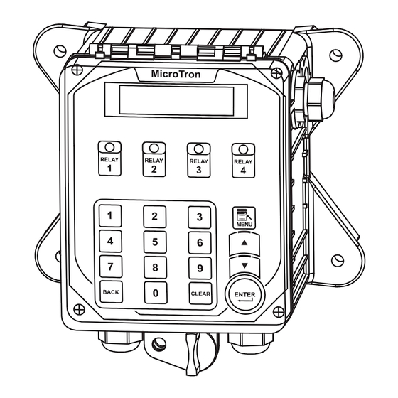
Page 6: Front Panel Description
Front Panel Description System initializes into RUN mode. Press this switch to toggle the controller MENU - from SET UP mode to RUN mode. Used to change the display from one line to the next. Submenus will UP/DOWN - return to the top menu loop when all options are displayed. ENTER - Used to access menus and accept changed values. -
Page 7: System Operation Overview
System Operation Overview MICROtron controllers have two modes of operation, RUN and SET UP. Both the RUN and SET UP menus are circular. Pressing the DOWN key in either menu will display the next line of information on the display. After the last item in a menu has been displayed, pressing the DOWN key will return the display to the top line of that menu. - Page 8 Repeat for Calibration Bleed Set Alarm List Timer1: (type) other timers Cal Temp 077°F Continuous Setpoint 01500 Disabled Password 0 Scroll down to see all active alarms Cal 02500µS Diff 0100 Flow Sw: C Post Timer Post Timer: ? Direction: Rise Units: Impe % of RUN: 000 High Alarm 2500...
-
Page 9: Micro-C Menu Map
eat for Water Meter Clock Set Manual Relay Diagnostics timers Password 0000 Reset Meter? N Set Time Force Relay: X MICRO-C Flow Sw: Close Meter Units Set Date Force: ON/OFF FW: ?.?.? Timer: ? Units: Imperial Meter Value Set Day & Week Timer mm:ss Test Keypad UN: 000... - Page 10 Repeat for Alarm List Timer1: (type) other timers Disabled Password Scroll down to see all active alarms Flow Sw: C Post Timer Post Timer: ? Units: Imp % of RUN: 000 Feed OK W 28-Day (Bio) A: All Days No Feed No A: All Weeks A: Start 12:00a A: Run Time hh:mm...
-
Page 11: Micro-F4 Menu Map
peat for Water Meter Clock Set Manual Relay Diagnostics er timers Password 0000 Reset Meter? N Set Time Force Relay: X MICRO-C Flow Sw: Close Meter Units Set Date Force: ON/OFF FW: ?.?.? t Timer: ? Units: Imperial Meter Value Set Day &... -
Page 12: Conductivity Sampling Methods
Conductivity Sampling Methods Continuous - Typical for most tower applications. The controller is constantly reading the sensor and activating the bleed relay based on readings relationship to the set point, set point direction and differential. Example: A rising set point of 1500 and differential of 50 the bleed relay would activate when the conductivity rises above 1500 and stays on until the reading drops to 1450. -
Page 13: Maintenance
Maintenance The only required maintenance for normal uninterrupted operation of your controller is cleaning of the electrode(s). After initial start up, it is a good idea to clean the electrode frequently until a schedule based on need has been developed. Since each application is unique, it is difficult to estimate the required frequency of cleaning. -
Page 14: Warranty & 30 Day Billing Memo Policy
VIII. Manufacturer’s Product Warranty Advantage Controls warrants units of its manufacture to be free of defects in material or workmanship. Liability under this policy extends for 24 months from date of installation. Liability is limited to repair or replacement of any failed equipment or part proven defective in material or workmanship upon manufacturer’s examination. - Page 16 Get the Advantage in Water Treatment Equipment Advantage Controls can give you the Advantage in products, knowledge and support on all of your water treatment equipment needs. Cooling Tower Controllers Boiler Blow Down Controllers Blow Down Valve Packages Solenoid Valves...
Need help?
Do you have a question about the MICROtron MICRO-C and is the answer not in the manual?
Questions and answers