Table of Contents
Advertisement
Quick Links
Download this manual
See also:
User Manual
I-7000 New Features
1. Internal Self Tuner
2. Multiple Baud Rates
3. Multiple Data Formats
4. Internal Dual WatchDog
5. True Distributed Control
6. High Speed & High
Density I/O
Warranty
All products manufactured by ICP DAS are warranted against
defective materials for a period of one year from the date of
delivery to the original purchaser.
Warning
ICP DAS assume no liability for damages consequent to the
use of this product. ICP DAS reserves the right to change this
manual at any time without notice. The information furnished by
ICP DAS is believed to be accurate and reliable. However, no
responsibility is assumed by ICP DAS for its use, nor for any
infringements of patents or other rights of third parties resulting
from its use.
Copyright
Copyright 2010 by ICP DAS. All rights are reserved.
Trademark
Names are used for identification purposes only and may be
registered trademarks of their respective companies.
I-7088
User Manual
I-7088 User Manual, Rev: A1.0
Your Powerful Tools
Create New Ideas
Create New Applications
1
Advertisement
Table of Contents

Related Manuals for ICP DAS USA I-7088


Summary of Contents for ICP DAS USA I-7088
- Page 1 Copyright Copyright 2010 by ICP DAS. All rights are reserved. Trademark Names are used for identification purposes only and may be registered trademarks of their respective companies. I-7088 User Manual, Rev: A1.0...
-
Page 2: Table Of Contents
2.18. $AACnF(Data)........... 39 2.19. $AACnM............41 2.20. $AACnMS ............43 2.21. $AACnP ............45 2.22. $AACnP(Data) ..........47 2.23. $AACnT............. 49 2.24. $AACnTS ............51 2.25. $AACnN ............53 2.26. $AACnNS............55 2.27. $AAF ..............56 I-7088 User Manual, Rev: A1.0... - Page 3 INIT* _pin Operation Principle ......88 PWM Operation Principle........89 Appendix............... 91 A.1 INIT Mode............91 A.2 Dual Watchdog Operation ........93 A.3 Frame Ground ............. 94 A.4 Node Information Area ........96 A.5 Reset Status ............97 I-7088 User Manual, Rev: A1.0...
-
Page 4: Introduction
Software Trigger PWM (Burst Mode) DI / Hardware Trigger The I-7088 has 8 PWM output channels and 8 counter inputs and can be used to develop powerful and cost effective analog control systems. PWM (Pulse width modulation) is a powerful... - Page 5 Refer to chapter 1 of the “I-7000 Bus Converter User Manual” for more information regarding the following: 1.1 I-7000 Overview 1.2 I-7000 Related Documentation 1.3 I-7000 Common Features 1.4 I-7000 System Network Configuration 1.5 I-7000 Dimensions I-7088 User Manual, Rev: A1.0...
-
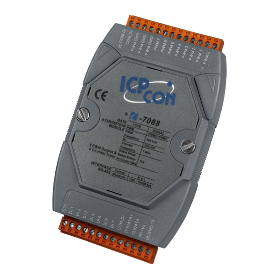
Page 6: Pin Assignment
1.1. Pin Assignments I-7088 User Manual, Rev: A1.0... -
Page 7: Specifications
72mm x 122mm x 35mm (W x L x H) Power Input Voltage Range 10 ~ 30 V Power Consumption 2.4 W (max.) Power Reverse Polarity Protection +/- 4 kV ESD , +/- 4 kV EFT and +/- 3 kV Surge Protection I-7088 User Manual, Rev: A1.0... -
Page 8: Block Diagram
Environment Operating Temperature -25 ~ 75° C Storage Temperature -40 ~ 85° C Humidity 5 ~ 95%, non-condensing 1.3. Block Diagram I-7088 User Manual, Rev: A1.0... -
Page 9: Application Wiring
1.4. Application Wiring 1.4.1. PWM Wiring Connection 1.4.2. DI/Counter Wiring Connection I-7088 User Manual, Rev: A1.0... -
Page 10: Quick Start
Step 1: Set the frequency of PWM channel 0 to 100KHz Step 2: Set the duty cycle of PWM channel 0 to 50.0% Step 3: Set PWM channel 0 to continuous mode Step 4: Start the output of PWM channel 0 I-7088 User Manual, Rev: A1.0... -
Page 11: Default Setting
Even parity and one stop bit Odd parity and one stop bit Configuration Code Table (TT) Input Range Counter Virtual Battery Backup Note: For type 52, the count value will continue from the last power off value. I-7088 User Manual, Rev: A1.0... -
Page 12: Dcon Protocol
Response Format: Leading Module Data [CHKSUM] Character Address CHKSUM A 2-character checksum that is present when the checksum setting is enabled. See Sections 1.7 and 2.1 for details. End of command character, carriage return (0x0D) I-7088 User Manual, Rev: A1.0... -
Page 13: Checksum Calculation
1. The Sum of the string = “!”+”0”+”1”+”2”+”0”+”0”+”6”+”0”+”0” = 21h+30h+31h+32h+30h+30h+36h+30h+30h = 1AAh 2. Therefore the checksum is AAh, and so the CHKSUM = “AA” 3. The response string with the checksum = !01200600AA(CR) Note: All characters should be in upper case. I-7088 User Manual, Rev: A1.0... - Page 14 Sets the duty cycle value 2.16 $AACnF !AA(data) Reads the frequency 2.17 $AACnF(data) Sets the frequency 2.18 Reads the status of continuous $AACnM !AAS 2.19 mode $AACnMS Sets the continuous mode 2.20 $AACnP !AA(data) Reads the steps value 2.21 I-7088 User Manual, Rev: A1.0...
- Page 15 Resets the host watchdog status 2.44 Reads the host watchdog timeout ~AA2 !AAETT 2.45 settings Sets the host watchdog timeout ~AA3ETT 2.46 settings ~AAI Sets Soft INIT 2.47 ~AATnn Sets the Soft INIT timeout value 2.48 I-7088 User Manual, Rev: A1.0...
-
Page 16: Aannttccff
The new type code, see Section 1.7 for details The new Baud Rate code, see Section 1.7 for details. For the I-7088, the rear slide switch must be moved to the INIT position in order to change Baud Rates. See Section A.1 for details. - Page 17 Changes to the Baud Rate and checksum settings take effect on the next power-on reset. 2. For the I-7088, changing the Baud Rate and checksum settings can only be achieved using software only and is performed by using the following commands: I.
- Page 18 I-7088 If the command is valid, the Baud Rate and checksum settings will be changed after the module responds with !AA. I-7088 User Manual, Rev: A1.0...
- Page 19 Examples: Command: #01 Response: >0000000800000090000000A000000B000000C000000D000000 E0000000F Reads module 01 and returns the count of DI channel 0 (8), channel 1 (9), etc. Related Commands: Section 2.3 #AAN I-7088 User Manual, Rev: A1.0...
-
Page 20: Aan
Response: >00000008 Reads data from channel 2 of module 03. Command: #029 Response: ?02 Reads data from channel 9 of module 02. An error is returned because channel 9 is invalid. Related Commands: Section 2.2 #AA I-7088 User Manual, Rev: A1.0... -
Page 21: Aa2
The data format, checksum settings and filter settings of the module, see Section 1.7 for details There will be no response if the command syntax is incorrect, there is a communication error, or there is no module with the specified address. I-7088 User Manual, Rev: A1.0... - Page 22 I-7088 Examples: Command: $012 Response: !01500600 Reads the configuration of module 01. Command: $022 Response: !02520600 Reads the configuration of module 02. Related Commands: Section 2.1 %AANNTTCCFF Related Topics: Section 1.7 Configuration Tables I-7088 User Manual, Rev: A1.0...
-
Page 23: Aa3N
Examples: Command: $030 Response: >FFFFFFFF Reads the maximum counter value of counter 0at address 01, return value 4294967295. Related Commands: Section 2.6 $AA3N(Data) I-7088 User Manual, Rev: A1.0... -
Page 24: Aa3N(Data)
Examples: Command: $030FFFFFFFF Response: !03 Sets the maximum counter value of counter 0 at address 01 to 4294967295, and returns the command was successful. Related Commands: Section 2.5 $AA3N I-7088 User Manual, Rev: A1.0... -
Page 25: Aa5
1: This is the first time the command has been sent since the module was powered on. There will be no response if the command syntax is incorrect, there is a communication error, or there is no module with the specified address. I-7088 User Manual, Rev: A1.0... - Page 26 $AA5 command has been sent since the module was powered-on. Command: $015 Response: !010 Reads the reset status of module 01. The response shows that there has been no module reset since the last $AA5 command was sent. I-7088 User Manual, Rev: A1.0...
-
Page 27: Aa5Vv
Examples: Command: $0153A Response: !01 Enables the DI counter for channels 1, 3, 4 and 5, and disables all other channels. The module returns a valid response. Related Commands: Section 2.9 $AA6 I-7088 User Manual, Rev: A1.0... -
Page 28: Aa6
Response: !013A Reads the channel status of module 01 and returns a response of 3A, meaning that channels 1, 3, 4 and 5 are enabled and all other channels are disabled. Related Commands: Section 2.8 $AA5VV I-7088 User Manual, Rev: A1.0... -
Page 29: Aa6N
Examples: Command: $0160 Response: !01 Resets the counter 0 of module 01 to the preset value and returns that the command was successful. Related Commands: Section 2.35 @AAGN, Section 2.36 @AAPN(Data) I-7088 User Manual, Rev: A1.0... -
Page 30: Aa6Nn
Examples: Command: $01601 Response: !01 Reset the counter 0 of module 01 to the preset value and returns that the command was successful. Related Commands: Section 2.35 @AAGN, Section 2.36 @AAPN(Data), Section 2.9 $AA6 I-7088 User Manual, Rev: A1.0... -
Page 31: Aa7N
1: The counter has exceeded the maximum counter value and the overflow flag has been set. There will be no response if the command syntax is incorrect, there is a communication error, or there is no module with the specified address. I-7088 User Manual, Rev: A1.0... - Page 32 Reads the status of the overflow flag for counter 0 of module 01 and returns that the counter has not been exceeded. Related Commands: Section 2.5 $AA3N, Section 2.6 $AA3N(Data), Section 2.10 $AA6N, Section 2.11 $AA6NN I-7088 User Manual, Rev: A1.0...
-
Page 33: Aab
Examples: Command: $01B Response: !0110 Reads the power down count of module 01 and returns a value of 16. Related Commands: Section 2.14 $AABR I-7088 User Manual, Rev: A1.0... -
Page 34: Aabr
Clear the power down count of module 01 and returns that the command was successful. Command: $01B Response: !0100 Read the power down count of module 01 and returns that a power down event has never happened. Related Commands: Section 2.13 $AAB I-7088 User Manual, Rev: A1.0... -
Page 35: Aacnd
Reads the duty cycle of PWM channel 0 and returns a value of 50%. Command: $01C1D Response: !0133.3 Reads the duty cycle of PWM channel 1 and returns a value of 33.3%. Related Commands: Section 2.16 $AACnD(Data) I-7088 User Manual, Rev: A1.0... -
Page 36: Aacnd(Data)
Sets the duty cycle of PWM channel 0 to 50% and returns the true output of 50%. Command: $01C1D33.4 Response: !0133.3 Set the duty cycle of PWM channel 1 to 33.4% and returns the true output of 33.3%. Related Commands: Section 2.15 $AACnD I-7088 User Manual, Rev: A1.0... -
Page 37: Aacnf
The actual frequency of the specified channel (000001 to 500000) There will be no response if the command syntax is incorrect, there is a communication error, or there is no module with the specified address. I-7088 User Manual, Rev: A1.0... - Page 38 Reads the frequency of PWM channel 0 and returns a value of 500 KHz. Command: $01C2F Response: !01000001 Reads the frequency of PWM channel 2 and returns a value of 1 Hz. Related Commands: Section 2.18 $AACnF(Data) I-7088 User Manual, Rev: A1.0...
-
Page 39: Aacnf(Data)
The actual frequency of the specified channel (000001 to 500000) There will be no response if the command syntax is incorrect, there is a communication error, or there is no module with the specified address. I-7088 User Manual, Rev: A1.0... - Page 40 333333 Hz. The duty cycle will be set to 33.3% automatically. Related Commands: Section 2.17 $AACnF Note: After using the $AACnF(Data) command, the duty cycle value will be reset to 50.0% automatically. I-7088 User Manual, Rev: A1.0...
-
Page 41: Aacnm
0: PWM continuous mode is disabled 1: PWM continuous mode is enabled There will be no response if the command syntax is incorrect, there is a communication error, or there is no module with the specified address. I-7088 User Manual, Rev: A1.0... - Page 42 Reads PWM continuous mode of channel 0 and returns that it is disabled. Command: $01C1M Response: !011 Reads PWM continuous mode of channel 1 and returns that it is enabled. Related Commands: Section 2.20 $AACnMS, Section 2.21 $AACnP, Section 2.22 $AACnP(Data) I-7088 User Manual, Rev: A1.0...
-
Page 43: Aacnms
Delimiter character for an invalid command The address of the responding module (00 to FF) There will be no response if the command syntax is incorrect, there is a communication error, or there is no module with the specified address. I-7088 User Manual, Rev: A1.0... - Page 44 PWM step value will be set to 1 automatically. Command: $01C1M0 Response: !01 Sets the PWM continuous mode of channel 1 to disabled and the PWM step value will not be affected. Related Commands: Section 2.19 $AACnM, Section 2.21 $AACnP, Section 2.22 $AACnP(Data) I-7088 User Manual, Rev: A1.0...
-
Page 45: Aacnp
The address of the responding module (00 to FF) (Data) PWM step value (0001 to FFFF) There will be no response if the command syntax is incorrect, there is a communication error, or there is no module with the specified address. I-7088 User Manual, Rev: A1.0... - Page 46 Reads the PWM step value for channel 0 and returns a value of 26 steps. Command: $01C1P Response: !011000 Reads the PWM step value for channel 1 and returns a value of 4096 steps. Related Commands: Section 2.19 $AACnM, Section 2.20 $AACnMS, Section 2.22 $AACnP(Data) I-7088 User Manual, Rev: A1.0...
-
Page 47: Aacnp(Data)
Delimiter character for an invalid command Address of the responding module (00 to FF) There will be no response if the command syntax is incorrect, there is a communication error, or there is no module with the specified address. I-7088 User Manual, Rev: A1.0... - Page 48 Sets the PWM step value for channel 1 to 4096 steps and the PWM continuous mode of channel 1 will be set to disabled automatically. Related Commands: Section 2.19 $AACnM, Section 2.20 $AACnMS, Section 2.21 $AACnP I-7088 User Manual, Rev: A1.0...
-
Page 49: Aacnt
1: The trigger start is enabled 2: The trigger stop is enabled There will be no response if the command syntax is incorrect, there is a communication error, or there is no module with the specified address. I-7088 User Manual, Rev: A1.0... - Page 50 Response: !010 Reads the status of the PWM channel 1 hardware trigger and returns the PWM channel 1 will not be affected when the rising edge of the DI is received. Related Commands: Section 2.24 $AACnTS I-7088 User Manual, Rev: A1.0...
-
Page 51: Aacnts
The address of the responding module (00 to FF) There will be no response if the command syntax is incorrect, there is a communication error, or there is no module with the specified address. I-7088 User Manual, Rev: A1.0... - Page 52 Command: $01C1T 0 Response: !010 Sets the status of the PWM channel 1 hardware trigger to disabled. The PWM will not be affect when the rising edge of the DI is received. Related Commands: Section 2.23 $AACnT I-7088 User Manual, Rev: A1.0...
-
Page 53: Aacnn
The address of the responding module (00 to FF) 0: Synchronization disabled 1: Synchronization enabled There will be no response if the command syntax is incorrect, there is a communication error, or there is no module with the specified address. I-7088 User Manual, Rev: A1.0... - Page 54 Reads the PWM channel 0 synchronization status and returns that it is enabled. Command: $01C1N Response: !010 Reads the PWM channel 1 synchronization status and return that it is disabled. Related Commands: Section 2.26 $AACnNS, Section 2.32 $AAYS I-7088 User Manual, Rev: A1.0...
-
Page 55: Aacnns
Examples: Command: $01C0N1 Response: !01 Sets the PWM channel 0 synchronization status to enabled. Command: $01C1N0 Response: !01 Sets the PWM channel 1 synchronization status to disabled. Related Commands: Section 2.25 $AACnN, Section 2.32 $AAYS I-7088 User Manual, Rev: A1.0... -
Page 56: Aaf
Command: $01F Response: !01A2.0 Reads the firmware version of module 01, and shows that it is version A2.0. Command: $02F Response: !02B1.1 Reads the firmware version of module 02, and shows that it is version B1.1. I-7088 User Manual, Rev: A1.0... -
Page 57: Aai
Examples: Command: $01I Response: !010 Reads the status of the INIT switch of module 01. The response shows that the INIT switch is in the INIT position. I-7088 User Manual, Rev: A1.0... -
Page 58: Aam
Examples: Command: $01M Response: !017088 Reads the name of module 01 and returns the name “7088”. Related Commands: Section 2.39 ~AAO(Name) I-7088 User Manual, Rev: A1.0... -
Page 59: Aar
There will be no response if the command syntax is incorrect, there is a communication error, or there is no module with the specified address. Examples: Command: $01R Response: !01 Resets the PWM and stops all of the outputs. I-7088 User Manual, Rev: A1.0... -
Page 60: Aaw
Examples: Command: $01W Response: !01 Saves the PWM configuration for all channels into EEPROM. After the next power on, the PWM configuration will automatically load from the EEPROM without giving any notification. I-7088 User Manual, Rev: A1.0... -
Page 61: Aays
Examples: Command: $01Y1 Response: !01 Starts the PWM output that has been set to synchronized. Command: $01Y0 Response: !01 Stops the PWM output that has been set synchronized. I-7088 User Manual, Rev: A1.0... -
Page 62: Aadodd
Delimiter character for an invalid command The address of the responding module (00 to FF) There will be no response if the command syntax is incorrect, there is a communication error, or there is no module with the specified address. I-7088 User Manual, Rev: A1.0... - Page 63 Related Commands: Section 2.34 @AADI Note: 1. When a host watchdog timeout occurs, the module will return an invalid response for this command and the PWM value that was sent is ignored. I-7088 User Manual, Rev: A1.0...
-
Page 64: Aadi
1 means that the DI is active. There will be no response if the command syntax is incorrect, there is a communication error, or there is no module with the specified address. I-7088 User Manual, Rev: A1.0... - Page 65 Reads the status of the PWM and DI and returns that PWM channel 0 is active and the others are inactive. DI channels 4, 5, 6 and 7 are active and the others are inactive. Related Commands: Section 2.33 @AADODD, Section2.37 ~AAD, Section 2.38 ~AADVV I-7088 User Manual, Rev: A1.0...
-
Page 66: Aagn
Examples: Command: @01G0 Response: !0100000000 Reads the preset count value for counter 0 of module 01 and returns that the preset value is 0. Related Commands: Section 2.36 @AAPN(Data) I-7088 User Manual, Rev: A1.0... -
Page 67: Aapn(Data)
Examples: Command: @01P000000000 Response: !01 Sets the preset count value for counter 0 of module 01 to 0 and returns that the command was successful. Related Commands: Section 2.35 @AAGN I-7088 User Manual, Rev: A1.0... -
Page 68: Aad
1: Input value 1 for high voltage Input value 0 for non-signal or low voltage There will be no response if the command syntax is incorrect, there is a communication error, or there is no module with the specified address. I-7088 User Manual, Rev: A1.0... - Page 69 I-7088 Examples: Command: $01D Response: !0101 Reads the miscellaneous settings of module 01 and returns Related Commands: Section 2.38 ~AADVV I-7088 User Manual, Rev: A1.0...
-
Page 70: Aadvv
Delimiter character for an invalid command The address of the responding module (00 to FF) There will be no response if the command syntax is incorrect, there is a communication error, or there is no module with the specified address. I-7088 User Manual, Rev: A1.0... - Page 71 I-7088 Examples: Command: $01D01 Response: !01 Sets the miscellaneous settings of module 01 and returns a valid response. Related Commands: Section 2.37 ~AAD I-7088 User Manual, Rev: A1.0...
-
Page 72: Aao(Name)
Response: !01 Sets the name of module 01 to “7088” and returns a valid response. Command: $01M Response: !017088 Reads the name of module 01 and returns the name “7088”. Related Commands: Section 2.29 $AAM I-7088 User Manual, Rev: A1.0... -
Page 73: Aard
Command: ~01RD10 Response: !01 Sets the response time to 16 milliseconds. Command: ~01RD Response: !0110 Reads the response time is 16 milliseconds and the response will be sent after 16 milliseconds have elapsed. Related Commands: Section 2.41 ~AARDTT I-7088 User Manual, Rev: A1.0... -
Page 74: Aardtt
Command: ~01RD10 Response: !01 Sets response time to 16 milliseconds. Command: ~01RD Response: !0110 Reads that the response time is 16 milliseconds and the response will be sent after 16 milliseconds have elapsed. Related Commands: Section 2.40 ~AARD I-7088 User Manual, Rev: A1.0... - Page 75 No response. Examples: Command: ~** No response Sends a “Host OK” command to all modules. Related Commands: Section 2.43 ~AA0, Section 2.44 ~AA1, Section 2.45 ~AA2, Section 2.46 ~AA3ETT Related Topics: Section A.2 Dual Watchdog Operation I-7088 User Manual, Rev: A1.0...
-
Page 76: Aa0
~AA1 command. There will be no response if the command syntax is incorrect, there is a communication error, or there is no module with the specified address. I-7088 User Manual, Rev: A1.0... - Page 77 Reads the status of the host watchdog of module 02 and returns 04, meaning that a host watchdog timeout has occurred. Related Commands: Section 2.42 ~**, Section 2.44 ~AA1, Section 2.45 ~AA2, Sec 2.46 ~AA3ETT Related Topics: Section A.2 Dual Watchdog Operation I-7088 User Manual, Rev: A1.0...
-
Page 78: Aa1
Resets the timeout status of the host watchdog of module 01 and returns a valid response. Command: ~010 Response: !0100 Reads the status of the host watchdog of module 01 and shows that no host watchdog timeout has occurred. I-7088 User Manual, Rev: A1.0... - Page 79 I-7088 Related Commands: Section 2.42 ~**, Section 2.43 ~AA0, Section 2.45~AA2, Section 2.46~AA3ETT Related Topics: Section A.2 Dual Watchdog Operation I-7088 User Manual, Rev: A1.0...
-
Page 80: Aa2
01 denotes 0.1 seconds and FF denotes 25.5 seconds. There will be no response if the command syntax is incorrect, there is a communication error, or there is no module with the specified address. I-7088 User Manual, Rev: A1.0... - Page 81 FF, which denotes that the host watchdog is enabled and the host watchdog timeout value is 25.5 seconds. Related Commands: Section 2.42 ~**, Section 2.43 ~AA0, Section 2.44 ~AA1, Section 2.46 ~AA3ETT Related Topics: Section A.2 Dual Watchdog Operation I-7088 User Manual, Rev: A1.0...
-
Page 82: Aa3Ett
Delimiter character for an invalid command The address of the responding module (00 to FF) There will be no response if the command syntax is incorrect, there is a communication error, or there is no module with the specified address. I-7088 User Manual, Rev: A1.0... - Page 83 Section A.2 Dual Watchdog Operation Note: When a host watchdog timeout occurs, the host watchdog is disabled and all of the PWM outputs are stopped. The ~AA3EVV command should be sent again to enable the host watchdog. I-7088 User Manual, Rev: A1.0...
-
Page 84: Aai
Delimiter character for an invalid command The address of the responding module (00 to FF) There will be no response if the command syntax is incorrect, there is a communication error, or there is no module with the specified address. I-7088 User Manual, Rev: A1.0... - Page 85 Sets the software INIT of module 01 and returns a valid response. Related Commands: Section 2.1 %AANNTTCCFF, Section 2.48 ~AATnn Related Topics: Section A.1 INIT Mode Note: The ~AATnn command should be sent prior to sending this command, see Section 2.48 for details. I-7088 User Manual, Rev: A1.0...
-
Page 86: Aatnn
Delimiter character for an invalid command The address of the responding module (00 to FF) There will be no response if the command syntax is incorrect, there is a communication error, or there is no module with the specified address. I-7088 User Manual, Rev: A1.0... - Page 87 Section 2.1 %AANNTTCCFF, Section 2.47 ~AAI Related Topics: Section A.1 INIT Mode Note: It is recommended that the software INIT timeout value is reset to 0 once any changes to the Baud Rate and checksum settings have been completed. I-7088 User Manual, Rev: A1.0...
-
Page 88: Operations Principle & Application Notes
EEPROM data. Step 4: record the EEPROM data for this I-7000 module Step 5: power off the module and disconnect the INIT*_pin and from GND_pin Step 6: power on the module I-7088 User Manual, Rev: A1.0... -
Page 89: Pwm Operation Principle
(2) The frequency is set to 1001Hz ~ 10000Hz, the duty cycle can be set to 01% ~ 99%. (3) Otherwise, the frequency and the duty cycle is not complete. Examples:The frequency 500000Hz (Support the I-7088 User Manual, Rev: A1.0... - Page 90 I-7088 duty cycle 50% only) The frequency 333333Hz (Support the duty cycle 33.3% and 66.6% only) The frequency 400000Hz (Modify the frequency to be 333333Hz and support the duty cycle 33.3% and 66.6% only) I-7088 User Manual, Rev: A1.0...
-
Page 91: Appendix
There are other commands that require the module to be in INIT mode. They are: 1. %AANNTTCCFF, which is used when changing the Baud Rate and checksum settings. See Section 2.1 for details. 2. $AAPN, see Section 2.20 for details. I-7088 User Manual, Rev: A1.0... - Page 92 7000 modules have the INIT switch located on the rear of the module to allow easier access to INIT mode. For these modules, INIT mode is accessed by sliding the INIT switch to the Init position, as shown below. I-7088 User Manual, Rev: A1.0...
-
Page 93: Dual Watchdog Operation
Dual Watchdog, making the control system more reliable and stable. For more information regarding the Dual Watchdog, please refer to Chapter 5 of the “Getting Started For I- 7000 Series Modules” manual that can be downloaded from the ICP DAS website http://www.icpdas.com. I-7088 User Manual, Rev: A1.0... -
Page 94: Frame Ground
2. Alternatively, connect the lower frame ground terminal to a wire and connect the wire to the earth ground, as shown in the figure below. I-7088 User Manual, Rev: A1.0... - Page 95 There is a screw at one end and a ring terminal is included, as shown in the figure below. Refer to Section 1.12.1 for more information about the new DIN- rail models. I-7088 User Manual, Rev: A1.0...
-
Page 96: Node Information Area
Baud Rate, etc. To access the node information areas, first slide the covers outward, as shown in the figure below. I-7088 User Manual, Rev: A1.0... -
Page 97: Reset Status
$AA5 command has been sent, it means that the module has been reset and the digital output value has been changed to the power-on value. I-7088 User Manual, Rev: A1.0...
Need help?
Do you have a question about the I-7088 and is the answer not in the manual?
Questions and answers