GRAUPNER mc-28 Programming Manual
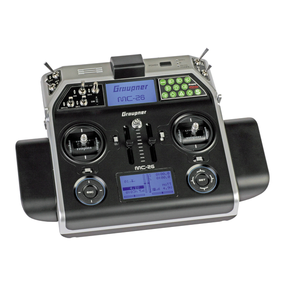
16 channel hott 2,4 ghz transmitter
Hide thumbs
Also See for mc-28:
- Manual (40 pages) ,
- User manual (36 pages) ,
- Programming manual (81 pages)

Related Manuals for GRAUPNER mc-28


Summary of Contents for GRAUPNER mc-28
- Page 1 Programming manual mc-26 / mc-28 / mc-28 4D 16 channel HoTT 2,4 GHz transmitter No. S1036 / 33028 / S1033 MC-28 MC-28 MC-28 MC-28 Part 2...
-
Page 3: Table Of Contents
Index Introduction ................7 Service Centre ................7 Use and menu functions ............8 Short-Cuts ..................8 Definition of terms ..............9 Receiver configuration ............10 Fixed-wing models ...............10 Helicopter models ...............11 Vehicles, boats ................11 Copter ..................12 Receiver power supply ..............12 Symbols explication .............. - Page 4 Model type ................25 Motor on CH1 ................26 Tail ....................26 Ailerons/Flaps ................27 Brake offset ..................27 Servo adjustment ..............27 Sticks setting ................29 Controls setting ..............29 Dual Rate / Expo ..............31 Throttle curve ................ 32 Switch display ................ 34 Control switch ................
- Page 5 FLAP -> ELE (flaps -> elevator) ............52 Free mixers ................53 MIX act. / Phase ..............56 Only mix channel ..............56 Dual mixer ................57 Fail Safe .................. 57 Trainer ..................58 Transmitter output ..............58 Profitrim ................. 59 Trim memory .................
- Page 6 Info display ................69 Digital trim / Throttle switch-off trim (function) ....69 Heli programming ..............70 Throttle curve (Heli) .............. 73 Sticks setting (Heli) ..............73 Control adjust (Heli) .............. 73 Ring limit ................75 Firmware update ..............76 Update through memory card .............76 Update through USB port ............77 Problems during firmware update ..........77...
-
Page 7: Introduction
If you experience any trouble during operation look through the instructions, ask your dealer or contact Graupner Service Centre. Due to technical changes, the information in this manual may be changed without prior notice. Keep updated on the products and... -
Page 8: Use And Menu Functions
Use and menu functions Short-Cuts The following key combinations can be used to directly call up cer- tain menus and options: CLEAR Brief simultaneous touch of the keys or on the right touch pad will restore the active entry field's changed parameter value back to its default value. -
Page 9: Definition Of Terms
Definition of terms Control function A control function is the signal for a specific control function. The signal of a control function can be transmitted directly into one con- trol channel or through a mixer to several control channels. The con- trol function includes the influence of the mechanical control path on the corresponding servo. -
Page 10: Receiver Configuration
Receiver configuration The servos must be connected to the receiver in the indicated sequence. Outputs that are not assaigned are available. To change the settings go to the “Model basic setting” menu and then the "Receiver outputs" line. Fixed-wing models Fixed-wing models with and without a motor with up to 4 ailerons and up to 4 flaps and tail type "normal"... -
Page 11: Helicopter Models
Helicopter models Receiver assignment for helicopter models with 1 to 3 swashplate servos free or special function free or special function free or governor or special function free or special function receiver power supply gyro suppression throttle servo or motor controller free or special function tail servo (gyro-system) Nick-1-servo... -
Page 12: Copter
Copter free or special function free or special function free or special function free or special function receiver power supply free or special function free or special function free or special function Nick Roll Motor/Pitch (up/down) receiver power supply free or special function Receiver power supply special function V-cable... -
Page 13: Symbols Explication
Symbols explication Always pay attention to the information indicated by this warning sign. Pay particular attention to information additionally marked CAUTION WARNING WARNING . The signal word indi- CAUTION cates the potential for serious injury The signal word indicates possibility of lighter injuries. Note The signal word indicates potential malfunctions. -
Page 14: Model Selection
Fail-Safe Fail Safe setting not performed yet setup t.b.d. Throttle or pitch control stick position or throttle limit for helicop- ters too high high! Connection between teacher and pupil transmitter disturbed pupil signal inser t No SD or SDHC memory card in the card slot or card not readable. SD card The transmitter has not been used within the time set from the line general settings"... -
Page 15: Copy/Delete
The selected model specific settings will be available in the menus. Now you can program your model in this model memory. The display changes to the base display of the new assigned model Select model type memory after the initialization of the selected model memory. Con- currently, a warning message that there is no connection with a receiver will appear for a couple of seconds. -
Page 16: Export To Sd Card
Copy Mod¢Mod Select the point "Copy Mod¢Mod" and confirm with the SET but- Copy from model: ton. GRAUBELE ULTIMATE You can always interrupt the process with the ESC button. STARLET BELL47G ––– • Select the model to copy and confirm the selection with the SET frei ... - Page 17 Copy phase Select the "Copy phase" point and confirm with the SET button. => Erase model => Copy model–>model You can always interrupt the process with the ESC button. => Expor t to SD => => Impor t from SD •...
-
Page 18: Suppress Menus
Suppress menus In this menu you can hide specific menu points from the menu func- Model select tion list. The hiding is related to the model memory. Copy / Erase Suppress menus Suppress models Select the menu point to hide or to show and switch the status with Base setup model the SET button. -
Page 19: Control Mode
Control mode In this function you can choose a control mode to be used for a Base setup model model memory. This function associates a control stick’s control Mod. Name GRAUBELE movement with a specific channel. Tap n the SET button, set the Stick mode Module HoTT... -
Page 20: Module
The binding type is indicated in the model memory list near the GRAUBELE model memory name: ULTIMATE STARLET "G" means global binding BELL47G ––– free "M" means model memory specific binding free Module You can select the fields in the lines with the left and right selection Base setup model buttons . -
Page 21: Receiver Binding
Receiver binding You can bind two receivers to the transmitter. The two bound receiv- ers can also be managed in binding option. You can split the control channels of the receivers in the "Receiver output". Binding process Move to the "N/A" field near the "HoTT" field with the selection but- Base setup model tons. -
Page 22: Receiver Output
Receiver output This function (Channel Mapping) is available if the line "Module" is Base setup model bound to at least one receiver. Here you can split the control chan- Mod. name GRAUBELE nels of the transmitter to the bound receivers. You can also freely Stick mode Module bind... -
Page 23: Dsc Port
Is the position of the receiver antennas correct? Are there any interference from electronic component in the model? If you have verified these conditions and you could not perform a successful range test, then please contact our Customer Service (see section "Service Center"). -
Page 24: Switch-On Warning
Switch-on warning This option allows you to program a question message the postion Base setup model of a switch or control so when the transmiter is switched on a warn- RF transmit ing willappear on the base display. RF Range Test 99sec DSC Output PPM10... -
Page 25: Model Type
Model type In this menu you can adjust the settings of the model type. For exam- Suppress models ple, you can select the tail and wing type or whether or not the Base setup model Model type model has a motor. Ser vo adjustment Stick mode. -
Page 26: Motor On Ch1
Motor on CH1 If you have selected airplane in the model selection, the line "Motor M o d e l t y p e at CH1" will appear. The settings here are previously described. Motor at C1 None Tail type Normal Aile/flaps 1AIL... -
Page 27: Ailerons/Flaps
Ailerons/Flaps In this line you can select the number of servos installed in the wings. M o d e l t y p e The following table shows the control channels to which the servos Motor at C1 None must be connected. Tail type nor mal Aile/flaps... - Page 28 Column 1 The first column lists the control outputs. 100% 100% 100% 100% The numbered servos refer to the servos connected to the corre- 100% 100% sponding receiver outputs, assuming that the transmitter and 100% 100% receiver outputs have not been switched. A change in the control 100% 100% mode does not influence the numbering of the servos.
-
Page 29: Sticks Setting
Sticks setting In this menu you can set the step value of the trim and the control Ser vo adjustment speed. These settings are valid for the channels one to four. The Stick mode Control adjust channels are listed with their function in the first column, according Dual Rate / Expo to the chosen model type. - Page 30 "Type" In this column you can select the control setting for this channel to ––– act globally "G" or according to the phase "PH". If the control is ––– assigned specifically to the phase, the related phase must be active. –––...
-
Page 31: Dual Rate / Expo
"- Trv +" Move the marking frame with the selection buttons over the "Off- +100% +100% set" column to the right side to reach this column. +100% +100% +100% +100% This column sets the control travel for both sides, together or sepa- +100% +100% rated for each side. -
Page 32: Throttle Curve
Expo Move the marking frame with the selection buttons over the +33% "SEL" column to the right side to reach the column. "EXPO" instead ––– of "DUAL" will be shown. ––– EXPO This function influences the travel of each control function. You can Nor mal set an exponential curve. - Page 33 The control curve is defined by up to 6 points (points of intersection) cur ve along the entire control stick path. The graphical representation Cur ve off Input +50% shows how the support points are set and adjusted. Output +50% Point 1 +50% In the first line, the effect of the curve function can be switched "on"...
-
Page 34: Switch Display
Switch display Channel 1 cur ve Switch display The switch display is a check function of the switches and control Control switch Logical switch switch in the transmitter. Announce Active switches are highlighted. On the right near the switch num- Phase settings ber, the switch position is displayed with a switch-symbol. -
Page 35: Logical Switch
Logical switch This function interconnects two switches, controls and/or logical Channel 1 cur ve switches. A "AND" or "OR" switch can be selected. You can program Switch display a total of eight logical switches ("L1 ... L8") in each model memory. Control switch Logical switch The result of such a logical switch function can be used as an alter-... -
Page 36: Phase Setting
Assigning the switch / Selecting the announce • In the column “ “ assign a switch (or an announce) for each Announce ––– switch position ––– • In the column "Type" decide if the announces act globally (GL) or ––– –––... -
Page 37: Motor
Time1 The times are only measured if the switch or control switch, assigned in the line "Lap time/Time tab." of the "Phase timer" menu, is "closed”. The frequency of the switch actuation is displayed in the basic display. This counter will be highlighted as soon as the switch for the "Time1"... -
Page 38: Phase Assignation
Announce Pha1 normal Here you can select an announce for each phase. The announce can Pha2 – Star t Pha3 – Strecke be selected from the supplied voice pack or from a user voice pack. – Pha4 Switching to the corresponding phase reproduces the announce. Pha5 –... -
Page 39: Channels Without Delay
Note The trim of "Elevator", "Aileron" and "Rudder" is factory-set to "Global". This setting can be changed at any time to "phase-specific" in the "Sticks setting" menu. Channels without delay Annnounce Phase settings In this menu, you can switch off the switching delay set in the "Phase Phase assignment Phase trim setting"... - Page 40 Defined as "stopwatch" or "motor runtime", the timer adds the switch-on time. If a value is not set in the "Timer" column, the timer counts up. If a value is set, the timer counts backward from this value. The buttons ...
-
Page 41: Phase Timer
Reset to the initial value by simultaneously tapping the or buttons of the right touch-pad. Frame This timer is started by an assigned switch. To stop the timer, switch the assigned switch to the "Off" position and press the ESC key. Reset to the initial value by simultaneously tapping the ... -
Page 42: Wing Mix
Good to know: What is a mixer? Each model memory has 8 freely programmable linear mixers, 4 freely programmable curve mixers and 4 cross-mixers. These mixers allow a control signal from one control to be mixed with another channel. Depending on the type of mixer, this can be adjusted lin- early, in the form of a curve or crosswise. -
Page 43: Programming Of The Wing Type
Programming of the wing type Model type: "1AIL" If "1AIL" in the "Aile/Flap" line of the "Model type" menu has been Wing mixers entered, the "Mixer menu" of your transmitter corresponds to the Brake settings figure on the left. All available parameters can be changed depend- –––... -
Page 44: Model Type: "2Ail
adjustment when extending the flaps and/or the speed-brakes. Aile -> Dir The aileron is associated with the rudder. In conjunction with the dif- Wing mixers ferentiation of the ailerons, the negative torque is compensated. Brake settings This allows a "clean" curve flight. The rudder remains separately con- –––... -
Page 45: Model Types With "2/4Ail 1/2/4Flap
Model types with "2/4AIL 1/2/4FLAP" All available parameters can be changed depending on the phase Wing mixers regardless of the selected combination of ailerons and flaps, . Multi-flap menu Brake settings Your transmitter corresponds to the figure on the left if you have Aile diff. -
Page 46: Model Type: "2Ail 4Flap
The options available in the Wing mix menu and its submenus +100% depend on the number of ailerons and flaps servos specified in the AI-Tr. +100% Diff. "Model type" menu. Only the necessary setting options are avail- AI Pos. able. With this setting, all options for the pair of ailerons are displayed. -
Page 47: Model Type: "4Ail 4Flap
Model type: "4AIL 4FLAP" If the servos are connected to the receiver as described in the sec- tion "Receiver assignment" and if you have selected in the "Model type" menu, the abbreviations "AILE", "AILE2", "FLAP" and "FLAP2" refer to the following flaps. left left left... -
Page 48: Multiflaps Menu
Multiflaps menu This menu is only displayed if at least two ailerons and one flap or Wing mixers more are selected in the "Model type" menu. The "AILE2" column Multi-flap menu and the "FLAP" and "FLAP2" columns are available in this menu to Brake settings Aile diff. - Page 49 ELE -> FLAP (ELEVATOR -> FLAP) Diff. FL pos. To support the elevator, the flap function can be influenced by the elevator control in a phase-specific manner with this mixer. Select the mixing directionto move the flaps downward when the elevator Nor mal is pulled ("up"), and conversely upward when the elevator is pushed ("down").
-
Page 50: Brake Setting
Brake setting The "Brake settings" menu is not shown if “yes” has been in entered Wing mixers in the "Model type" menu "Motor on CH1 front / rear" and in the Multi-flap menu Brake settings column "Motor" of the "Phase setting" menu for the currently active Aile diff. - Page 51 D.red (Differentiation reduction) If you use the aileron differentiation, the aileron effect is strongly Brake settings affected by the deflection of the ailerons. Justification: a further Butt D.red excursion of the one aileron is almost impossble and the control sur- AI cur ve face moving downward does not reach the "normal"...
-
Page 52: Ail -> Rud (Aileron -> Rudder)
AIL -> RUD (aileron -> rudder) In this mixer, the aileron is entrained by the aileron control. In con- junction with the differentiation of the ailerons, the negative torque Wing mixers Multi-flap menu is compensated. This allows a "clean" curve flight. The rudder Brake settings remains separately controllable. -
Page 53: Free Mixers
Free mixers In this menu you can find free programmable linear and curve mix- Phase timers ers. Wing mixers Free mixers In each model memory there are eight available linear mixers with MIX active/phase the designation M1 to M8 and four curve mixers with the designa- MIX-only channel Dual mixer tion C9 to C12. - Page 54 In a series switch of mixers, the mixed signal of the channel from the upstream mixer is used as the input not the direct control signal of the channel. P : This option includes the trim values from the "Phase trim" menu of the input channel as a function of the phase.
- Page 55 Offset (mixer neutral point) The dotted vertical line in the middle of the graphic indicates the position of the mixer neutral point ("offset"). This is the point on the control travel where the mixer does not affect the control channel. By default this point is in the control center.
-
Page 56: Mix Act. / Phase
Trim X-axis function C.Mix 9 Kur ve Trim X axis This function can be activated by tapping the left-hand or the right Input +35% selection button of the right-hand touch panel while the value Output –37% Point 2 –55% field is active. You can then move the active point horizontally or ver- nor mal tically using the selection buttons. -
Page 57: Dual Mixer
Dual mixer Dual mixer Mixer1 In this menu, you can link two control functions with four freely pro- Mixer2 Mixer3 grammable dual mixers. Mixer4 Diff. Example (V-tail mixer): Elevator control stick Rudder / Elevator left V-Tail mixer Rudder / Elevator right Rudder control stick In the case of a dual mixer, the control signals are output from the two controls to both outputs of the mixers. -
Page 58: Trainer
Trainer In this menu set the functions for the teacher / student operation. T/P:Pupil The operation can be wireless or wired with HoTT transmitters. Please also observe the instructions of the pupil transmitter. Pupil Teacher 2 3 4 5 Connection through cable (DSC port): SW: –––... -
Page 59: Profitrim
Profitrim This function is for fast, direct trimming of the aileron and flap posi- Profi trim tions. The trim range of the controls is about ±25 % . OFF OFF In the line "TR" determined which of the two control surfaces pairs –––... -
Page 60: Trim Memory
Trim memory Storage of the trim position Trim memory In the left column (POS) the value of the trim is shown. Now tap the AILE SET button. The trim value is transferred to the memory. The trim ELEV value is now displayed in the "SET" column on the right side. The bar RUDD display in the main display shows again the center position. -
Page 61: Channel Sequencer
ALARM SETTING - Tap the SET button to display a list. Telemetry TEL.RCV BIND. 1 In the first line, select "OFF" to disable the function of this menu. SETTING & DATA VIEW SENSOR Select "Vario" to interrupt or supplement by program-defined RF STATUS VIEW VOICE TRIGGER announcements the standard output of vario sound. -
Page 62: Multichannel
Start, stop and additional noises as well as vehicle-type signals Sound switch for ship models No. 2382.S Start, stop and additional noises as well as ship-type signals You can find further information on www.graupner.com. Alternatively, contact your dealer or Graupner Service Center. 62 / 80 33028_mc_28_Teil2_jh... - Page 63 Required receiver settings: In the "SETTINGS & DATAVIEW" menu set "20 ms". In the "SETTINGS & DATAVIEW" menu set "SAME". The control channel in use should not be used either as an input or as an output channel of a mixer. In the "Multi- channel"...
-
Page 64: Mp-3 Player
MP-3 Player Fi l e n o t fo un d If the message "no files" appears, the transmitter has not found any suitable MP3 files on the inserted SD card or there is no SD card in Vol:15 ––– the transmitter. -
Page 65: Control Mode (Preset)
Control mode (preset) Here select the control mode preset during a new model memory set up. This selection determines which control functions are assigned to the control sticks. In the "Receiver assignment" menu, you can see which control function is output on which channels. Changing the control mode in an existing model memory is only pos- sible in the "Basic setting model"... -
Page 66: Stick-Type (Only By Mc-26)
Stick-type (only by mc-26) Potentio. - Setting for when standard gimbal sticks with potentiome- ters are used. 4D-stick - Setting for when optional 4D-stick gimbal sticks with poten- tiometers are used. Module The transmitter is equipped with a HoTT RF module as standard. External RF modules from other manufacturers can be connected to the DSC and DATA sockets. -
Page 67: Switch-On Melody
Data log for the external Bluetooth module (No. 8351) and for trans- mitting telemetry data and voice output on smartphones and tablets with "Graupner HoTT Viewer App for Android". Ph. Name 1 … 10 Here you can input your own phase names. These names are dis- played when you activate the phase. -
Page 68: Vibration
To delete the secret number, tap the SET key twice. The transmitter can only be unlocked with the correct secret num- ber or by the service department of Graupner. 68 / 80 33028_mc_28_Teil2_jh... -
Page 69: Info Display
Info display This menu shows information about the transmitter and the SD card. RFID ABCDEF12 fir mware ver. 1.234 The date and time can be set here. date 2016/09/17(Sa ) 18:19:20s time RFID - Identity number of the transmitter SD-CARD 3896MB Firmware version - shows the version of the transmitter firmware available... -
Page 70: Heli Programming
Heli programming Select model type Select a free model memory from the "Model selection" menu and define the model type with the "Heli" icon. Specific functions for the heli programming are displayed in the following menus. (Please also refer to the previous descriptions of the individual menus) Suppress models Programming step-by-step: Base setup model... - Page 71 • Swashplate linearization: Helicopter type Swashplate 3Sv(2rol) For Flybarless systems, select "no" here. For paddle head sys- Linear. swashpl. tems, the setting "yes" can prevent unwanted side effects: a Rotor direct right Pitch min. back pitch change when the roll function is activated or tensions between the linkage of the swash plate servos.
- Page 72 5. Phase assignation menu: Announce • Switch off the autorotation switch Phase settings Phase assignment • Select the switch for the normal flight phase and switch it off in Non-delayed chan Timer (general) the correct position. Phase timers • Select combination C and press the SET key Phase assignment •...
-
Page 73: Throttle Curve (Heli)
Throttle curve (Heli) Setting the curve is explained in the previous description of the Ser vo adjustment menu "Throttle curve". Note the curve characteristic set here acts as Stick mode Control adjust an input signal on mixers of the "Helicopter mix" menu. Dual Rate / Expo Channel 1 cur ve »Heli-Mischer«... - Page 74 Channel 7 - Gyro Current gyro systems can be adjusted for a smooth, proportional ––– effect. You can also choose between two different modes of action Thro ––– with the transmitter. Gyro ––– ––– If the Gyro has this option, specify "Normal" Gyro action and "Head- Nor mal ing Lock operation"...
-
Page 75: Ring Limit
Ring limit This function is used to control up to three of the so-called Ring limiter Voith-Schneider drives of ship models. The function only appears in the multi-function menu when the model type "Boat" has been selected. Input Output In the "Input" column, select the two channels to be used for con- trolling the drive unit. -
Page 76: Firmware Update
Only operate your transmitter using the current software version. these information can also be found at: www. graupner.com => Service & Support => Update and revi- sion history for GRAUPNER HoTT components. Before each update, check the transmitter battery charge ... -
Page 77: Update Through Usb Port
During the update the transmitter cannot be switched on. After 30 seconds the transmitter switches on. Declaration of conformity S1033 / S1036 / 33028 - mc-26 / mc-28 / mc-28 4D Graupner/SJ declares that the product is conform to EU norms. EMV 2004/108/EC: EN 301 489-1 V1.9.2... -
Page 78: Notes On Environmental Protection
Warranty The Graupner, Henriettenstrassee 96, 73230 Kirchheim/Teck grants from the date of purchase of this product for a period of 24 months. The warranty applies only to the material or operational defects already existing when you purchased the item. - Page 79 79 / 80 33028_mc_28_Teil2_jh...
Need help?
Do you have a question about the mc-28 and is the answer not in the manual?
Questions and answers