GRAUPNER mz-10 HoTT Manual
6 channel 2,4 ghz transmitter
Hide thumbs
Also See for mz-10 HoTT:
- Operating instructions manual (16 pages) ,
- User manual (40 pages)
Table of Contents
Advertisement
Quick Links
Advertisement
Table of Contents

Related Manuals for GRAUPNER mz-10 HoTT


Summary of Contents for GRAUPNER mz-10 HoTT
- Page 1 Manual mz-10 HoTT 6 channel 2,4 GHz transmitter No. S1042 No. S1042.77 mz-10...
- Page 2 2 / 48 S1042_sh_V1...
-
Page 3: Table Of Contents
Control sticks centering force ............16 Transmitter power supply .............17 Installing the batteries ...............17 Optional power supply with battery pack .........18 Polarity of the mz-10 HoTT charging socket ......18 Receiver power supply ..............18 Foreword ................. 19 Transmitter startup ..............20 Transmitter status indications ............20 LED panel and keys ...............21... - Page 4 Acceding to the transmitter programming mode .....31 Region setting ................31 System menu - Control mode .............32 Servo direction and model type ..........34 Fail Safe ..................36 Teacher/Student (T/S) ..............40 Switch functions .................42 Firmware update ..............44 Transmitter software update ............44 SIMPLIFIED DECLARATION OF CONFORMITY ......46 Notes on environmental protection .........
-
Page 5: Introduction
Introduction Thank you very much for purchasing a Graupner mz-10 HoTT trans- mitter. Read the manual carefully to use the transmitter optimally and first of all to safely control your models. If you experience any trouble during operation, take the instructions to help or ask your dealer or Graupner Service Centre. -
Page 6: Intended Use
• Battery box • Programming connector • Receiver GR-12L (only with S1042) • Manual Note Graupner/SJ constantly works on the development of all products; we reserve the right to change the item, its technology and equip- ment. 6 / 48 S1042_sh_V1... -
Page 7: Technical Data
Technical data Transmitter mz-10 HoTT Frequency band 2,4 … 2,4835 GHz Modulation FHSS Controller 16-Bit-Microcontroller Transmitting power 100 mW Model memory 5 functions of which 4 can be Control functions trimmed Teacher/Pupil function Wireless Temperature range -10 … +55 °C... -
Page 8: Symbol Description
Symbol description Always observe the information indicated by these warning signs. Particularly those which are additionally marked with the words CAUTION or WARNING. WARNING The signal word indicates the potential for serious injury, CAUTION the signal word indicates possibility of lighter injuries. The signal word Note indicates potential malfunctions. -
Page 9: For Your Safety By Handling The Transmitter And The Receiver
For your safety by handling the transmitter and the receiver WARNING Also while programming the transmitter, make sure that a motor connected in the model cannot accidentally start. Disconnect the fuel supply or drive battery beforehand. CAUTION Avoid every kind of short-circuit in all sockets of the transmitter and of the receiver! Risk of fire! Use only the suitable connectors. -
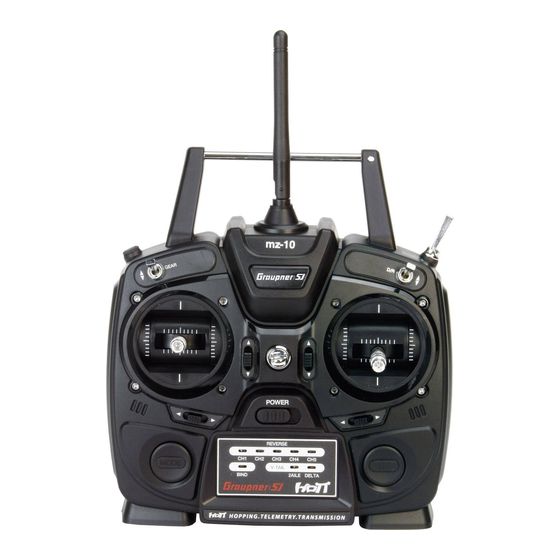
Page 10: Description Of The Transmitter
Description of the transmitter Package content mz-10 antenna integrated in the case Eyelet for neck strap D/R switch (switch function between 70 % and 100 % servo travel of the control functions 2, 3 and 4) TRAINER switch (see use mode) Right-hand control stick ARROW button Trim... - Page 11 Alternatively, the transmitter mz-10 HoTT can be equipped with a firmware version suitable for the operation of copters. See section "Firmware Updates" on the last pages of this manual for more infor- mation. mz-10 antenna integrated in the case Eyelet for neck strap...
- Page 12 mz-10 Case screws Battery case cover Data socket to connect - a programming connector - an optional SMART BOX - a Bluetooth module - an interface adapter to update the transmitter Charging socket CAUTION The charge port is intended to charge an optional battery pack. Never use it with non rechargeable batteries.
-
Page 13: Connections And Fixtures
= Plus line (red) = Minus line (brown or black) You can find more information about the listed accessories on www.graupner.de. Digital trim with an acoustic feedback The two control sticks have digital trimming. Briefly touch the trim- ming switch to move the neutral position of the control stick by a specific value with each click. -
Page 14: Transmitter Preparation
Transmitter preparation Adjusting the length of the control sticks Length of both control stick can be adjusted. Hold down the bottom half of the knurled grip, and loosen the screwed connection by turn- ing the top part. You can now lengthen or shorten the control stick by screwing it up or down. - Page 15 Closing step by step 1. Check if the upper and the lower part of the transmitter housing are correctly coupled and the tiny cables are properly placed. 2. Screw the housing screws in their original position. 3. Reconnect the battery box. Transmitter antenna integrated in the handle Adjust screws for brake spring (outer) and ratchet (inner) Stick self centering force adjust screws...
-
Page 16: Neutralizing The Control Sticks
Neutralizing the control sticks Neutralizing step by step Locate in the left control stick gimbal the screw surrounded by a white circle in the picture. Turn the screw toward the inside of the transmitter until the relevant control stick can move freely from stop to stop, or turn it outward until the control stick resets itself independently. -
Page 17: Transmitter Power Supply
Transmitter power supply The mz-10 HoTT transmitter normally includes normally 4 non-re- chargeable batteries. These are NOT rechargeable. Installing the batteries WARNING Alkaline batteries (dry batteries) should not be recharged. Acute risk of explosion! Note Pay attention when inserting the batteries to the correct position and make sure the contacts are solid. -
Page 18: Optional Power Supply With Battery Pack
WARNING Follow the safety instructions included with the batteries! Polarity of the mz-10 HoTT charging socket Make sure that the polarity of the charge cable is the same as the charge port. The charge cables of other manufacturers have often reversed polarity. -
Page 19: Foreword
Foreword The mz-10 HoTT transmitter can be used to control aircraft, land and watercraft models or alternatively to control copters, depending on the firmware version that has been imported via firmware update. The following sections of this manual are accordingly marked with model type symbols. -
Page 20: Transmitter Startup
The mz-10 HoTT transmitter is normally delivered in "NORMAL" use mode and "GENERAL" region setting. For the "normal" use yu do not need to change anything. -
Page 21: Led Panel And Keys
LED panel and keys After switching on the transmitter the LEDs on the LED panel blink or light for approx. 5 seconds to indicate the actual correct settings. V-TAIL BIND 2AILE DELTA MODE button 1. Push and hold while switching on the transmitter .. -
Page 22: Led Panel And Keys
LED panel and keys After switching on the transmitter the LEDs on the LED panel blink or light for approx. 5 seconds to indicate the actual correct settings. 4 4 5 Cut-o Rate BIND -100% +100% MODE button 1. Push and hold while switching on the transmitter .. -
Page 23: Use Mode Selection
"Fail safe". Note The mz-10 HoTT transmitter remains after a conversion of the con- trol mode in the last selected use mode until this will be changed. This is completely independent from the occurred setting of the TRAINER switch and even after switching on again the transmitter. -
Page 24: Binding
When binding, make sure that the transmitter antenna is always far enough away (1 to 2 meters) from the receiver antenna(s). Note The mz-10 HoTT can only be bound in "NORMAL" use mode. Make sure, before starting the "binding" process, that the transmitter is in this use mode. -
Page 25: Range And Function Test
Sensors eventually installed in the model have to be connected to this receiver, because the transmitter will indicate only the values coming from the back channel of the last bound receiver. All other receiver work in parallel to the last receiver bound to the transmit- ter. - Page 26 If this is not 100 % the case, do not use the system and contact your Service at Graupner/SJ GmbH. 10. Perform a range test before each flight, and simulate all servo movements that could occur during the flight.
-
Page 27: Range Warning
In case the transmitter cannot set a connection to a proper back channel or during the use an existing connection is interrupted, the transmitter mz-10 HoTT BIND LED turns off and the buzzer indicates it with a 4 times beep signal (back channel missing), after that with a 3 times beep following (transmission interference to the receiver). -
Page 28: Use And Setting
Use and setting Supported model types With the standard firmware of the mz-10 HoTT transmitter, water and land vehicles, as well as surface planes with up to two aileron control servos for standard models, as well as V-tail and flying-wing / delta models with two aileron/elevator servos can be controlled: •... -
Page 29: Receiver Assignation
Receiver assignation Attention The servos must be connected to the receiver in the indicated sequence. Outputs that are not required are not assigned. • Fixed wing model with or without motor and with 1 aileron servo Free or receiver power supply Free or telemetry or special function Rudder Elevator... -
Page 30: Transmitter Programming
Due to the different installation of the servos and rudder linkages in the model, the direction for certain servos can be reversed. In a V-tail: Servo with wrong direction of Solution rotation Reversed rudder and elevator Change servo 3 + 4 direction The rudder is correct and the Switch servos 3 + 4 on the elevator is reversed... -
Page 31: Acceding To The Transmitter Programming Mode
Acceding to the transmitter programming mode Switch the transmitter off and connect the included programming connector in the "DATA / S + -" port on the transmitter back side. Region setting • Switch on the transmitter. Pay attention to the number of the beeps. Buzzer ... -
Page 32: System Menu - Control Mode
System menu - Control mode There are four different ways of assigning the four control functions of aileron, elevator, rudder and throttle or airbrake flaps of a wing model or roll, nick, yaw and motor/pitch control of a copter of both sticks. - Page 33 Control mode MODE 1 (Throttle/Pitch right) MODE 2 (Throttle/Pitch left) Nick Throttle/Pitch Throttle/Pitch Nick Nick Throttle/Pitch Throttle/Pitch Nick MODE 3 (Throttle/Pitch right) MODE 4 (Throttle/Pitch left) Nick Throttle/Pitch Throttle/Pitch Nick Nick Throttle/Pitch Throttle/Pitch Nick Programmed steps control mode 1. Accede to the transmitter programming mode, as described before.
-
Page 34: Servo Direction And Model Type
RX SERVO menu in the receiver. Model Type In the mz-10 HoTT transmitter you can select one of the standard configurations. The setting is carried out as described below under "Programming step-by-step". - Page 35 "2AILE" For models with 2 aileron servos. By aileron actuation the servos connected to the outputs 2 and 5 work in parallel. The aileron trim acts on both servos. Note A conversion of "CH5" has in this case no effect. "DELTA"...
-
Page 36: Fail Safe
A short beep is emitted after release. 7. As after every transmitter switching on, the seven LEDs light and/ or blink for approx. 5 seconds to indicate the actual selected set- tings. Fail Safe The "Fail Safe" function determines the response of the receiver both by directly switching on the receiver system and when there is an interruption in transmission from the transmitter to receiver. - Page 37 • Note that the chosen fail safe settings are saved in the receiver. The fail safe settings should be restored after changing a receiver and should be deleted in the previous receiver by resetting. • In the course of storing fail-safe settings, any change to "France" will be lost and must be renewed.
- Page 38 Programming step-by-step 1. Select the desired mode 2. Use the controls on the transmitter to move the servos of the model to the desired positions and hold them. 3. Press the MODE button to the left of the LED field for three to four seconds to store these items in the receiver.
- Page 39 After releasing the button the status LED and the acoustic signal should indicate the actual transmitter (power on) "control mode" status. 3. Check the settings by switching the transmitter off. If analogue servos can not be moved by hand, repeat the proce- dure.
-
Page 40: Teacher/Student (T/S)
To conclude preparations, bind the training model to the pupil trans- mitter. From a mz-10 HoTT teacher transmitter all the five channels will be transmitted to the pupil transmitter. Pupil transmitter After the training model has been completely programmed into the... - Page 41 Bring the mz-10 HoTT teacher transmitter in "TEACHER" use mode or program the other teacher transmitter accordingly to its manual. Pupil transmitter Bring the mz-10 HoTT pupil transmitter in "PUPIL" use mode or pro- gram the other pupil transmitter accordingly to its manual. Note...
-
Page 42: Switch Functions
In the canter switch position ("TEACHER") of a teacher's transmitter mz-10 HoTT the teacher's transmitter controls all control functions. In the upper, self-centering, switch position ("PUPIL"), the pupil can control the model as long as the switch is held by the teacher in this position. - Page 43 Note When the motor-stop function is on the red CUT-OFF-LED blinks. Attitude/Rate mode switching • Attitude mode Rate mode The stick movements determinate the Copter reaction on Roll and Nick. It allows a maximal angle of about 50° at 100% of stick movement.
-
Page 44: Firmware Update
7168.6A or 7168.S, which are available separately. The programs and files required can be found in the Download area for the corresponding products at www.graupner.de. Download this software package from the Internet, and unpack it on your computer. All other information can be found in Internet in the same page where the software package is available. - Page 45 • Finally you will be asked to switch the transmitter on: push the MODE button on the mz-10 HoTT transmitter while you switch it on. Release the MODE button as soon as the transmitter has been recognized: "Found target device ...".
-
Page 46: Simplified Declaration Of Conformity
SIMPLIFIED DECLARATION OF CONFORMITY Graupner/SJ hereby declares that the S1042 mz-10 HoTT complies with the Directive 2014/53/EU. The full text of the EU Declaration of Conformity is available at the following Internet address: www.graupner.de 46 / 48 S1042_sh_V1... -
Page 47: Notes On Environmental Protection
These operating instruction are exclusively for information purposes and are subject to change without prior notification. The current version can be found on the Internet at www.graupner.de on the relevant product page. In addition, the company Graupner/SJ has no responsibility or liability for any errors or inaccuracies that may appear in construction or operation manuals.
Need help?
Do you have a question about the mz-10 HoTT and is the answer not in the manual?
Questions and answers