
Related Manuals for GRAUPNER S1036.77


Summary of Contents for GRAUPNER S1036.77
- Page 1 Manual mc-26 16 channel HoTT 2,4 GHz transmitter No. S1036.77 MC-26 MC-26 MC-26 MC-26 Part 1...
-
Page 3: Table Of Contents
Index Introduction ................. 5 Service Centre ..............5 Intended use ............... 6 Target group ............... 6 Package content ..............6 Technical Data ..............7 Symbols explication ............7 Safety notes ................ 7 For your safety by handling the transmitter ......8 For your safety by handling the battery ....... - Page 4 Hidden mode ..............28 Firmware update/Changing the display language ..... 29 Telemetry data display ............30 Firmware update ............... 32 Update through memory card .......... 32 Update through USB port ..........33 Problems during firmware update ........33 Declaration of conformity ..........34 Notes on environmental protection ........
-
Page 5: Introduction
Introduction Thank you very much for purchasing the Graupner mc-26 HoTT transmitter. Read this manual carefully to achieve the best results with your transmitter and first of all to safely control your models. If you experience any trouble during operation, take the instructions to help or ask your dealer or Graupner Service Centre. -
Page 6: Intended Use
Read through this entire manual before you attempt to install or use the transmitter. Graupner/SJ constantly works on the development of all prod- ucts; we reserve the right to change the item, its technology and equipment. Target group The product is not a toy. -
Page 7: Technical Data
Technical Data Transmitter mc-26 HoTT Frequency band 2,4 … 2,4835 GHz Modulation FHSS Transmitting power 100 mW EIRP Control functions 16 functions of which 4 can be trimmed Temperature range -10 … +55 °C Antenna Patch integrated in the case Operating voltage 3,4 …... -
Page 8: For Your Safety By Handling The Transmitter
Operation and use of radio-controlled models needs to be learned! If you have never operated a model of this type before, start carefully and make yourself familiar with the model's reactions to the remote control commands. Pro- ceed always responsibly. Inform yourself before flying your ... -
Page 9: For Your Safety By Handling The Battery
CAUTION Risk of fire! Avoid every kind of short-circuit in all sockets of the transmitter! Use only the suitable connectors. In no case the electronic component of the transmitter may be changed or modified. Due to licensing reasons, any reconstruction and/or modification of the product is prohibited. - Page 10 Leaked electrolyte is caustic and should not be touched or come into contact with your eyes. In case of emergency, rinse with a large quantity of water and consult a Med. Doc- tor. Always charge the battery fully. ...
-
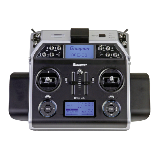
Page 11: Description Of The Transmitter
Description of the transmitter Control elements on the transmitter MC-26 MC-26 MC-26 MC-26 Connection sockets (protected by a cover) Control sticks: 2 sticks for a total of 4 independent control functions Speaker Antenna (integrated in the case) ON/OFF switch LED indicators (battery, RF radiation, warning signals, charge indicator) Places for switches and buttons As standard are installed: 12 switches with different designs, 2 INC/DEC buttons Right rotary control "SD1"... - Page 12 Five housing screws and six screws for the hand pads SW16/PB18 SW17/PB19 Connection socket for transmitter battery (pay attention to the correct polarity) 12 / 36 S1036.77_jh_V1_de...
-
Page 13: Inside View
Inside view 1 Sockets for optional transmitter controls and switches (connection sequence as preferred) 2 Lithium battery 3 RF module 4 SW17/PB19 (when transmitter is closed) 5 Transmitter battery plug 6 SW16/PB18 (when transmitter is closed) 13 / 36 S1036.77_jh_V1_de... -
Page 14: Interfaces
Interfaces Provided connection Left provided connections 1- DSC socket On the left side is located the DSC socket. This socket allows the trainer/pupil function and the use of flight simulators. For more information on the DSC socket and the trainer/pupil function see the section "DSC socket". -
Page 15: Dsc Socket
This type of connection should therefore only be used if you protect yourself from electrostatic discharge while operating the simulator by wearing a commercially available grounding armband. Graupner therefore strongly recommends only using wireless simulators. Perform any necessary adaptations in the menu. -
Page 16: Memory Cards
Note Make sure that all the plugs are securely inserted in the respective sockets, and only use the provided plug-in connections with a 2-pin jack plug on the DSC side. In the "Transmitter setting" submenu, you can set one of the following modes in the "DSC output"... -
Page 17: Display And Touchpad
"NoName". In the folder "Models" are saved the exported model memories. The data can be evaluated on a compatible computer using the programs found on the downloads page for the transmitter under www.graupner.de. Display and touchpad Alpina 30 0:00.0 0:00.0... -
Page 18: Symbols In The Display
Symbols in the display Telemetry symbols in the display The active model memory has not yet been bound to a receiver. Not flashing: RF transmitter function switched off. Blinking antenna symbol: Last receiver bound to the active model memory is inactive or out of reach No telemetry signal to receive Signal strength display of the model connection Signal strength display of the connection with pupil transmitter... - Page 19 Keys to the left of the display SET key 1. Briefly pushing the SET key will cause a jump from the dis- played base screen to the multi-function menu. 2. In the settings menu activate (confirm) the settings fields by pressing the SET button.
-
Page 20: Commissioning
Commissioning Hand pads Installing the hand pads The hand pads have to be installed on the sides of the transmit- ter. Hold the hand pad exactly upon the six holes and fix it with the 6 fixing screws. Use the same procedure for the other hand pad. -
Page 21: Anchorage For The Transmitter Belt
Anchorage for the transmitter belt On the upper side of the transmitter there is an eyelet which can be used to hook a neck-strap. Opening/closing the transmitter housing The transmitter should be opened only in the following cases: If a self centering stick has to be converted in non self cen- tering ... -
Page 22: Sticks Conversion
Sticks conversion Neutralization Both control sticks can be set from neutralizing to non-neutral- izing. Neutralizing step by step: Locate in the left control stick gimbal the screw surrounded by a white circle in the picture. Turn the screw toward the inside of the transmitter until the rel- evant control stick can move freely from stop to stop, or turn it outward until the control stick resets itself independently. - Page 23 General commissioning Notice-safety query throttle position As soon as the transmitter is switched on then the throttle position is checked. If the throttle position is not in the motor-off area, then the drive motor may start in an uncontrolled manner. This check is performed by all the models with the setting "Motor at CH1 front/ back".
-
Page 24: Switch The Transmitter Off
Switch the transmitter off If you push on the POWER button, by switched on transmitter, for more than 2 sec. a safety query appears (see image). Select the desired option with one of the pouch pads (up or down) and Power off push the SET button. -
Page 25: Charging The Transmitter Battery
Charging the transmitter battery You have two charge possibilities: 1. Removing the battery from its case and charging it with a charger WARNING The charger should always be supervised during charge and it should be used only in rooms fitted with a smoke detector. Removing transmitter battery Remove the battery case cover. -
Page 26: Use And Menu Functions
Use and menu functions Short-Cuts The following key combinations can be used to directly call up certain menus and options: CLEAR Brief simultaneous touch of the keys or on the right four way keys will restore the active entry field's changed parameter value back to its default value. - Page 27 Select the desired menu point with the selection keys and con- Sepecial funct. firm with the SET key. Global functions The description of the single menu point is available in the pro- gramming manual (Manual part 2) on www.graupner.de. 100% 100% Hidden menu options 100% 100% 100% 100% In some menus specific setting options are available but hidden.
-
Page 28: Hidden Mode
German, English, French, Dutch, Italian and Spanish, Czech and Russian. The most actual language packets are available on www. graupner.de. Language change Language change step by step: Insert the included memory card in its slot as described in the "Memory card"... -
Page 29: Firmware Update/Changing The Display Language
Firmware update/Changing the display language Note Before each update, check the transmitter battery charge or charge it as a precaution, and save all model memories so that they can be restored if necessary. Note Follow the "Firmware update step by step" manual steps from the section "Firmware update"... -
Page 30: Telemetry Data Display
The flashing arrows indicate in which direction you have to push STICK CALIBRATION the sticks. CONTRAST LANGUAGE ENGLISH VOICE DEUTSCH Confirm by pushing the SET key. STICK CALI. With the selection keys of the right four way keys allow you to cyclically select the positions of the four calibrated sticks. - Page 31 Receiver This display offers a graph of the data from the display "RX DAT- RX–S QUA: 100% RX–S ST.: 100% AVIEW“ of the "Telemetry" menu "SETTINGS, DISPLAYS". RX–dBm: –33dBm TX–dBm: –33dBm V–PACK: 10ms Value Explanation RX–SPG.:4.8V CH OUTPUT TYPE:ONCE M–RX V :4.6V +22°C RX-S Quality expressed as a percentage of the signal packages from the transmitter arriving at the receiver...
-
Page 32: Firmware Update
Only operate your transmitter using the current software version. these information can also be found at: www.graupner.de => Service & Support => Update and revision history for GRAUPNER HoTT components. Before each update, check the transmitter battery charge or ... -
Page 33: Update Through Usb Port
Update through USB port Download the actual software package from the Internet, and unpack it on your computer. Connect your switched off trans- mitter with your PC, by using the included USB cable, which is supplied with the package content, plug USB cable directly to the micro USB port of the transmitter and the other end to a free port in your computer. -
Page 34: Declaration Of Conformity
Simplified EU declaration of conformity Hereby, Graupner/SJ declares that the radio equipment type mc-26 is in compliance with Directive 2014/53/EU. The full text of the EU declaration of conformity is available at the following internet address: www.graupner.de 34 / 36... -
Page 35: Notes On Environmental Protection
The cur- rent version can be found on the Internet at www.graupner.de the relevant product page. In addition, the company Graupner has no responsibility or liability for any errors or inaccuracies that may appear in construction or operation manuals.
Need help?
Do you have a question about the S1036.77 and is the answer not in the manual?
Questions and answers