GRAUPNER mz-10 HoTT S1001 User Manual
Hide thumbs
Also See for mz-10 HoTT S1001:
- Operating instructions manual (16 pages) ,
- Manual (48 pages)
Table of Contents

Related Manuals for GRAUPNER mz-10 HoTT S1001


Summary of Contents for GRAUPNER mz-10 HoTT S1001
- Page 1 Manual mz-10 HoTT No. S1001 mz-10 Manual...
- Page 2 2 / 40 S1001_jp_V1...
-
Page 3: Table Of Contents
Index Introduction ................. 5 Service Centre ..............5 Intended use ............... 6 Target group ..............6 Package content ..............6 Technical Data ..............7 Symbols explication ............8 Safety notes ................ 8 For your safety by handling the transmitter ....... 9 For your safety by handling the batteries ...... - Page 4 Range and function test ..........22 Operation and settings ............ 24 Supported model types ..........24 Receiver configuration ............ 25 Transmitter programming ..........27 Country setting ............27 Control mode ............28 Servo direction and model type ....... 29 Fail Safe ..............31 Teacher/Student (T/S) ..........
-
Page 5: Introduction
Introduction Thank you very much for purchasing the Graupner mz-10 HoTT transmitter. Read this manual carefully to achieve the best results with your transmitter and first of all to safely control your models. If you experience any trouble during operation, take the instructions to help or ask your dealer or Graupner Service Centre. -
Page 6: Intended Use
Read through this entire manual before you attempt to install or use the transmitter. Graupner/SJ constantly works on the development of all prod- ucts; we reserve the right to change the item, its technology and equipment. Target group The product is not a toy. -
Page 7: Technical Data
Technical Data Transmitter mz-10 HoTT Frequency band 2,4 … 2,4835 GHz Modulation FHSS Controller 16-Bit-Microcontroller Resolution 1024 Transmitting power 100 mW Model memory Control functions 5 functions of which 4 can be trimmed Teacher/Pupil function Wireless Temperature range -10 … +55 °C Antenna folding and rotating Operating voltage... -
Page 8: Symbols Explication
Symbols explication Always observe the information indicated by this warning sign. Particularly those which are additionally marked with the CAU- TION or WARNING. The signal word WARNING indicates the poten- tial for serious injury, the signal word CAUTION indicates possibil- ity of lighter injuries. -
Page 9: For Your Safety By Handling The Transmitter
Protect all equipment from dust, dirt, moisture. All equip- ment must be protected from vibration as well as excessive heat or cold. The models may only be operated remotely in normal outside temperatures such as from -10°C to +55°C. For your safety by handling the transmitter WARNING Also while programming the transmitter, make sure that a con-... -
Page 10: Description Of The Transmitter
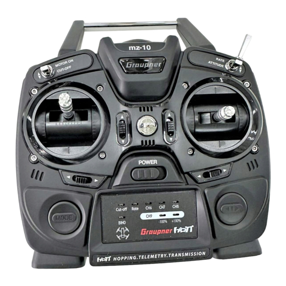
Description of the transmitter Control elements on the transmitter mz-10 Antenna with folding and swivel joint Eyelet for neck strap Dual rate switch (70 % / 100 % servo travel of the control functions 2, 3 and 4) TRAINER switch (see use mode) Right control stick ARROW buttons... - Page 11 mz-10 1 Case screws 2 Battery case cover 3 Data socket to connect: - programming connector - optional SMART BOX - Bluetooth module - Interface adapter to update the transmitter 4 Charge port (to charge an optional battery pack, NOT for non-re- chargeable batteries) 11 / 40 S1001_jp_V1...
-
Page 12: Connections And Fixtures
= signal line (orange) = Plus line (red) = Minus line (brown or black) You can find more information about the listed accessories on www.graupner.de. Digital trim Digital trim with an acoustic feedback The two control sticks have digital trimming. -
Page 13: Commissioning
Commissioning Adjust screws for brake spring and ratchet Neutralization lever Screw to convert from neutralizing to non neutralizing Stick self centering force adjust screws Brake spring and ratchet Opening/closing the transmitter housing The transmitter should be opened only in the following cases: ... -
Page 14: Control Sticks Length Adjustment
Open step by step: Before opening the housing switch the transmitter off. Open the battery case. Remove the battery box lifting it from one side and gently release it from the velcro tape. Unplug the connector. Unscrew the eight screws with a cross screwdriver. Hold both housing halves with both hands and let the screws fall on a proper surface turning the transmitter upside-down. -
Page 15: Brake Spring And Ratchet
Note The right control stick gimbal is specular to the left one, so that here the screw is located left under the middle. Brake spring and ratchet The outboard screw of the two marked in the figure adjust the braking force. The inboard screw adjusts the strength of the ratchet for the respective control stick. -
Page 16: Transmitter Power Supply
Transmitter power supply The mz-10 HoTT transmitter normally includes normally 4 non-re- chargeable batteries. Installing the batteries WARNING Alkaline batteries (dry batteries) should not be recharged. Acute risk of explosion! Note Pay attention when inserting the batteries to the correct position and make sure the contacts are solid. -
Page 17: Optional Power Supply With Battery Pack
Note The charging socket comes standard with a protection switch that protects against polarity reversal. Original Graupner automatic char- gers recognize the battery charge. In order to prevent damage to the protection switch and to the other components, charging current should never exceed 1 A. -
Page 18: Transmitter Commissioning
After switching the transmitter on the central status LED in the top blinks red and an acoustic signal is emitted, to indicate the last programming status, see following chart. Graupner LED (red) Buzzer Description Solid on... -
Page 19: Led Panel And Keys
LED panel and keys MODE buttons allows the binding between transmitter and receiver so as selection and to confirm different settings as control mode, fail safe, servo reverse, tail, etc... Servo reverse channel (CH) 1 - 5 red LED blinking = normal direction red LED solid on = reverse BIND LED indicates if transmitter and receiver are bound... - Page 20 After every activation of the "NORMAL" use mode: The transmitter will be in program mode "Fail safe". The buzzer beeps each 2 seconds and contemporary the status LED blinks. The country setting, even if changed to "FRANCE", will be set to "GENERAL" so as the position of the digital trim will be set to "neutral".
-
Page 21: Binding
Binding Binding the mz-10 transmitter When binding, make sure that the transmitter antenna is always far enough away (1 to 2 meters) from the receiver antenna. Note The mz-10 HoTT can only be bound in "NORMAL" use mode. Make sure, before starting the "binding" process, that the transmitter is in this use mode. -
Page 22: Range Warning
Range warning In general, an acoustic range warning is emitted once the receiver signal in the feedback channel becomes too weak. Since the transmitter's output is significantly higher than the receiver, the model can always be operated safely. For safety you should reduce the model distance, until the signal quits again. - Page 23 If this is not 100 % the case, do not use the system and con- tact your Service at Graupner/SJ GmbH. 10. Perform a range test before each flight, and simulate all servo movements that could occur during the flight.
-
Page 24: Operation And Settings
Operation and settings Supported model types Up to two aileron servos by normal models so as V-tail and all- wing/delta models with two aileron/elevator servos are sup- ported. NO mixer active: 1 central aileron servo for both wings Rudder Elevator Preprogrammed mixers of the mz-10 HoTT transmitter: ... -
Page 25: Receiver Configuration
Receiver configuration Attention The servos must be connected to the receiver in the indicated sequence. Outputs that are not required are not assigned. If only 1 aileron servo is used for both ailerons the receiver output 5 for the right aileron remains free. So that this output is available for special functions. - Page 26 Due to the different installation of the servos and rudder linkages in the model, the direction for certain servos can be reversed. In a V-tail: Servo with wrong Solution direction Reversed rudder and elevator Direction servo 3 + 4 Rudder correct, elevator reversed Switch servos 3 + 4 on the receiver Elevator correct, rudder reversed Change servo 3 + 4 direction and...
-
Page 27: Transmitter Programming
Transmitter programming CAUTION Safely interrupt the fuel line or the power supply in your model, so that during the programming the motor cannot start accidentally. Notes Within an activation of the described below rotation procedure for setting the desired locale and control arrangement, however, only one option can always be activated. -
Page 28: Control Mode
Control mode There are four different ways of assigning the four control func- tions of aileron, elevator, rudder and throttle or airbrake flaps of a wing model of both sticks. The options that are chosen depend on the individual preferences of the model pilot. »MODE 1«... -
Page 29: Servo Direction And Model Type
Servo direction and model type Switch on the transmitter without programming connector. The servo direction and model type options can be selected in each of the three operating modes (NORMAL, TEACHER, PUPIL). Push for at least 2 seconds the left arrow button near the LED field. - Page 30 Note Through the available optional SMART BOX the servo can be individually adapted to the model necessity in the RX SERVO menu in the receiver. Model type setting In the mz-10 transmitter you can select one of the standard con- figurations.
-
Page 31: Fail Safe
Model type LED … Description normal "2AILE" blinks each of the up to 5 servos are "DELTA" blinks controlled separately 2AILE "2AILE" lights on Outputs 2 + 5 for aileron control "DELTA" blinks coupled DELTA "2AILE" blinks Outputs 2 + 3 for aileron and "DELTA"... - Page 32 Pay attention in the following described setting, that an already con- nected motor does not start accidentally during the test of the selected option. Note that the chosen fail safe settings are saved in the receiver. The fail safe settings should be restored after changing a receiver and should be deleted in the previous receiver by resetting.
- Page 33 The transmitter is now again in control mode. Check the settings by switching the transmitter off. Correct or repeat the programming if the servos do not move to the desired position. Mode "Hold" In case of transmission interruptions, all servos programmed to "hold"...
-
Page 34: Teacher/Student (T/S)
Teacher/Student (T/S) An mz-10 transmitter can be combined with any suitable HoTT transmitter for a wireless Teacher-Pupil system. But: Completely independently from the related teacher transmitter defaults in a pupil transmitter type mz-10 HoTT the training model MUST ALWAYS be bound to the pupil transmitter. In addiction it is absolutely essential for correct training that the model memory active in the teacher model is not bound to any receiver. - Page 35 Preparing teacher and pupil transmitter: Teacher transmitter Bring the mz-10 teacher transmitter in "TEACHER" use mode or program the other teacher transmitter accordingly to its man- ual. Pupil transmitter Bring the mz-10 pupil transmitter in "PUPIL" use mode or pro- gram the other pupil transmitter accordingly to its manual.
-
Page 36: T/S Mode
T/S mode NOTE Before starting trainer mode for the operational model, be sure to check whether all the functions have been correctly transferred. In the central switch position ("TEACHER") an mz-10 teacher transmitter this transmitter takes the complete control functions, in the upper switch position ("PUPIL") of the teacher transmitter the pupil can control the model, until the (self-neutralizing) TRAINER switch is released. -
Page 37: Firmware Update
Only operate your transmitter using the current software version. These information can also be found at: www.graupner.de => Service & Support => Update and revision history for GRAUPNER HoTT components. Before each update check the transmitter battery charge status. -
Page 38: Declaration Of Conformity
• Switch off the transmitter and interrupt the USB connection to the PC. Declaration of conformity S.1001 mz-10 HoTT Graupner/SJ declares that the product is conform to EU norms. EMV 2004/108/EC: EN 301 489-1 V1.9.2 EN 301 489-17 V2.1.1 EN 62479:2010... -
Page 39: Notes On Environmental Protection
The present construction or user manual is for informational pur- poses only and may be changed without prior notice. The cur- rent version can be found on the Internet at www.graupner.de on the relevant product page. In addition, the company Graupner has no responsibility or liability for any errors or inaccuracies that may appear in construction or operation manuals.
Need help?
Do you have a question about the mz-10 HoTT S1001 and is the answer not in the manual?
Questions and answers