GRAUPNER mz-32 HoTT Manual
32 channel 2.4 ghz transmitter
Hide thumbs
Also See for mz-32 HoTT:
- Manual (48 pages) ,
- Reference manual (42 pages) ,
- Reference manual (51 pages)
Table of Contents
Advertisement
Quick Links
Advertisement
Table of Contents

Subscribe to Our Youtube Channel
Related Manuals for GRAUPNER mz-32 HoTT


Summary of Contents for GRAUPNER mz-32 HoTT
- Page 1 Manual mz-32 HoTT 32 channel 2.4 GHz transmitter P/N. S1024, S1024.77...
-
Page 2: Table Of Contents
Table of Contents Introduction ............................... 5 Service Centers ..............................5 Intended Use ..............................6 Target Group ..............................6 Package Content ..............................6 Technical Data ..............................7 Symbol Description ............................8 Safety Notes ............................... 8 For Safety! Handling the Transmitter ......................8 For Safety! Handling the battery ........................ - Page 3 Creating a Model ............................23 Stick Mode Preset Change ..........................23 Deleting a Model ............................24 Main Display Symbols ..........................25 Receiver Binding .............................. 26 Bind Group ..............................26 Binding a Model ............................... 27 Removing Existing Bind ........................... 27 Multi Receiver Binding ............................ 27 Range Test ..............................
- Page 4 FCC INFORMATION ............................46 IC INFORMATION ............................. 47 Notes on environmental protection ....................... 48 Care and Maintenance ............................ 48 Warrant Conditions ............................48 Page 4 of 49 S1024.mz-32-V2.1-EN...
-
Page 5: Introduction
Introduction Graupner mz-32 HoTT Thank you for purchasing a transmitter. To get the most out of your mz-32, read the manual carefully before use and operation. If you experience any trouble during operation, consult this Graupner manual first or ask assistance from your dealer or Service Center. -
Page 6: Intended Use
If you do not have sufficient knowledge about dealing with radio-controlled models, please contact an experienced modeler or a model club. Package Content • Transmitter mz-32 HoTT • Receiver GR-24L (S1024) • Transmitter display and programming stand •... -
Page 7: Technical Data
Approx. 210 x 195 x 105mm 8.27 x 7.68 x 4.13in Weight approx. 1120g/39oz with battery Note The technical information of Graupner receivers can be found in the related receiver system manual or online. WiFi Frequency Range 2412 MHz ~ 2474 MHz Frequency Band IEEE 802.11 b/g/n HT20... -
Page 8: Symbol Description
Symbol Description Always observe the information indicated by this warning sign. In Particularly those which are additionally marked with the words CAUTION or WARNING. The word WARNING indicates the potential for serious injury, the signal word CAUTION indicates possibility of lighter injuries. The signal word Note indicates potential malfunctions. -
Page 9: For Safety! Handling The Battery
• Never program your transmitter while normally using the model. This can result in both inattention when controlling and incorrect programming. CAUTION Avoid any kind of short-circuit in all sockets of the transmitter and of the receiver! Risk of fire! Use only suitable connectors. In no case the electronic component of the transmitter or of the receiver may be changed or modified. - Page 10 charge, this may indicate a defect in that cell. Do not use the battery pack any longer! • The batteries may not be modified. Do not directly solder or weld the cells. • If handled improperly, there is a danger of fire, explosion, irritation and burns.
-
Page 11: Description Of The Transmitter
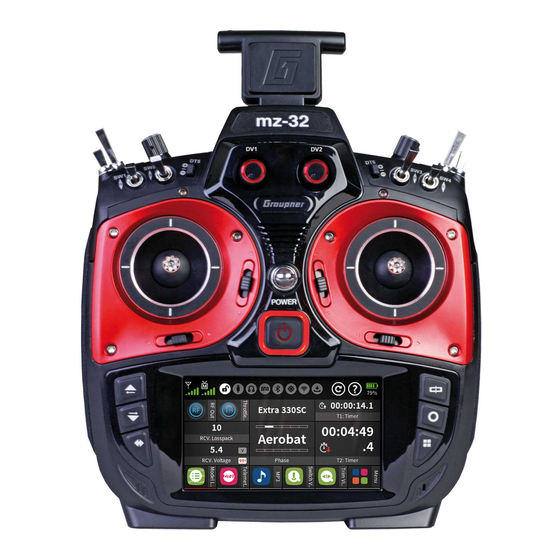
Description of the Transmitter Control Elements on the Transmitter 3-way position switch SW5 2-way position switch SW6 Digital button DT7 Proportional dial DV3 Foldable transmitter antenna Transmitter handle Proportional dial DV4 Digital button DT8 3-way switch SW8, top push-switch, bottom latching switch 3-way switch SW7 Page 11 of 49... -
Page 12: Transmitter Front
Transmitter Front Display Scroll through menu pages Scroll through menu pages Scroll through menu pages Trim button for the left control stick Left control stick Proportional dial DV1 3-way switch SW1 3-way switch SW8, 1x push-switch, 2x latching-switch Digital button DT5 Digital button DT6 3-way switch SW3 3-way switch SW4... -
Page 13: Transmitter Backside
Transmitter Backside Battery case cover Gimbal tension screw for horizontal control function no function Gimbal tension screw for vertical control. Lower screw is for tension of the control stick Proportional rotary control LV2 Inner screw adjusts brake force Outer screw adjusts ratchet's strength Transmitter handle Foldable transmitter antenna Cover flap for audio, COMM, DATA and DSC connection... -
Page 14: Keys To The Left Of The Display
Keys to the left of the display Also referred to as upper, center and lower selection keys. These keys are used to scroll through lists, columns, etc., in the same way as their arrow directions. • Data Log function Pressing the lower left button for about one second switches the data logging function of the transmitter ON or OFF. -
Page 15: Data Connection
Transmitter Note Once connected to a PC or other USB power source, a yellow LED should be mz-32 HoTT lit solidly to the left of the 's micro-USB port. If this LED flashes yellow or is even dark, the power source is too weak to charge the transmitter. - Page 16 Mass storage memory If the mz-32 HoTT transmitter is connected to a compatible PC and the "Mass storage" field is activated by tapping, the memory of the transmitter can be accessed from the PC. For example, to copy screenshots or model data from the transmitter to the PC or MP3 or software updates to the transmitter.
-
Page 17: Control Stick
Transmitter Preparation Control Stick Length Adjustment Both sticks can be adjusted in length: By holding the lower half and turning the upper part of the knurled handle, the screw is loosened. The control stick is extended or shortened by turning it up or down and then fixed by screwing each against each other of the upper and lower part of the handle. -
Page 18: Transmitter Power
Transmitter Power The mz-32 HoTT transmitter is normally delivered with a 9000 mAh 1s3p LiHV battery. Installing the Battery Note Pay attention when inserting the battery to the correct position and make sure the contacts are solid. Interruptions of the power supply to the... -
Page 19: Starting The Transmitter
These two clocks can also be installed as widgets on one of your user widget decks. Starting the Transmitter Switch Transmitter ON Pressing the front ON / OFF switch for about 1 second switches the mz-32 HoTT transmitter on. Initial Setup If the transmitter is still in the delivery status or the transmitter was previously reset to factory settings in the "Info &... - Page 20 (Multirotor) MODE 1 (Throttle/Pitch right) MODE 2 (Throttle/Pitch left) Nick Throttle/Pitch Throttle/Pitch Nick Throttle/Pitch Nick Throttle/Pitch Nick MODE 3 (Throttle/Pitch right) MODE 4 (Throttle/Pitch left) Nick Throttle/Pitch Throttle/Pitch Nick Nick Throttle/Pitch Throttle/Pitch Nick (Surface and Water) MODE 1 (Throttle/Pitch right) MODE 2 (Throttle/Pitch left) Nick Throttle/Pitch...
- Page 21 Date & Time In this display, the current date and time is entered or corrected as part of the initial setup of the transmitter. Setting date and time 1. Tap on the desired value field. This is displayed in white and selection fields are displayed at the bottom of the display.
-
Page 22: Transmitter Switch Off
Transmitter Switch Off Press the front ON / OFF switch and hold it until the "Switch off" message display appears. Tapping "back" stops the process. Touching "OK" switches off the transmitter. Alternatively, press and hold the ON / OFF switch until the transmitter shuts off The operation of the display is analogous to the operation of other touch- Menu Functions... -
Page 23: Renaming A Model
6. Select the desired stick mode or tap cancel to return to the previous display without changing the stick mode. Stick Mode Preset Change 1. Tap the blue “System” menu tab. 2. Tap the icon "System Set" in the top left corner. 3. -
Page 24: Deleting A Model
Deleting a Model Deleting a model 1. Tap the green "Basic" menu tab. 2. Tap the "Model List" menu tab. 3. In the "No." column, touch the model number of the model to be deleted. 4. Touch the "Basket" icon. A safety dialog will be displayed. -
Page 25: Main Display Symbols
Main Display Symbols RF status of the transmitter RF status of the receiver Screen lock on/off USB connection connected/not connected Headphones connected/not connected DSC cable connected/not connected Bluetooth on/off GPS signal available/not available WLAN connected/not connected Data logging on/off Widget and data clear icon Help icon Battery status, tapping switches between % and Volt Note... -
Page 26: Receiver Binding
Receiver Binding To establish a connection with the transmitter, a Graupner HoTT receiver must first be "bound" to at least one model memory. This process is generally called "binding" and it needs to be repeated each time a new receiver is installed in a model. -
Page 27: Binding A Model
1. Move the transmitter and receiver at a moderate distance from each other (30cm or 1ft). 2. Switch on the mz-32 HoTT transmitter without switching on the RF or set the RF Transmission to "OFF" in the "RF Set" field of the "RF Set"... - Page 28 The transmitter does not automatically enable each bound receiver as part of the channel count. This must be done manually in the RF Set menu. For example, if RX1 is an 8-channel receiver it will serve only channels 1 to 8 on that receiver.
-
Page 29: Range Test
Range Test When the range test starts, the output of the transmitter is significantly decreased. A practical functional test can therefore be performed at less than 100 m or 300 ft. After the end of the range test, the transmitter switches back to full output power and the range test signal tone stops. -
Page 30: Digital Switches
Digital Switches The mz-32 HoTT transmitter features 64 digital switches. These can be found in the “Special” menu and can be defined, activated and switched in the submenu “Digital Switch”. In addition, each of these 64 Digital Switches can be arbitrarily placed as a widget on one of the widget pages and operated from there. -
Page 31: Assign Digital Switches To Widgets
Switching to level allows the direct connection of transistors or LEDs to the receiver output via a series resistor. • For Graupner receivers GR-12 (#33506), GR-16 (#33508), GR-24 (#33512), GR-32 (#33516) and GR-24 PRO (#33583) as well as GR-16L (#S1021), GR-24L (#S1022) and GR-32L (#S1023) series resistors are already installed and LEDs can be connected directly between the orange servo pulse wire and the brown or black “-”... -
Page 32: Assigning Digital Switches On Rx
Assigning Digital Switches on RX You can also assign a digital output switches over the Telemetry connection directly in the receiver. To avoid malfunctioning when assigning digital switches, only the affected receiver may be in operation during their switch assignment. 1. -
Page 33: Setting Controls And Mixers
Setting Controls and Mixers Both the control characteristics in the submenu Control Set in the basic menu as well as virtually all mixer programming is essentially done in the same way. The corresponding procedure is shown below with reference to the throttle curve. -
Page 34: Setting A Curve
Setting a Curve 1. Tap on the “Value” menu tab. 2. Move the vertical green line with the control stick to the to the desired point. The selected point is displayed in red and on the right the number of the point as well as its coordinates are shown in orange rectangles at the lower and left display edge. -
Page 35: Stick Calibration
Stick Calibration If the center position of the self-neutralizing control stick does not correspond exactly to 0% control travel you will need to calibrate your control sticks. This can be best accomplished with a new model. 1. Change to the “Model list” submenu and create a new model. Any model type will do. -
Page 36: Servo Display
Servo Display The Servo View monitor can be called upon at any time by pressing the servo monitor key on the right side of the radio. The view represents the active positions of any control or switch including mixers. The default screen shows channel 1 … 16. A swipe from the bottom to the top will reveal the additional channels. -
Page 37: Telemetry
Telemetry The telemetry connection between the transmitter and receiver takes place via the return channel of the HoTT receiver defined as the main receiver. If more than one receiver is bound to a model memory, the return channel will be by default the last bound receiver. This assignment can be changed in the submenu “RF Set”... -
Page 38: Telemetry Cycle
Attention This also changes the assignment in the column "T. sel." of the submenu "RF Set". After completing the adjustments, it may be necessary to restore the original assignment! Telemetry Cycle In those situations where for example two airplane models are about to be operated at close proximity to another controlled by two separate transmitters you may choose to reduce or eliminate the telemetry back channel of one of the models to avoid potential interference. - Page 39 Note • The height of the bar is a measure of the reception level expressed as logarithmic values with the unit dBm (1mW = 0dBm). • 0 dBm corresponds to the two baselines in the above graph. Consequently, the level is poorer the higher the bar and vice versa.
-
Page 40: Setting & Data View
Setting & Data View This display visualizes the settings and menus of the connected receiver. If there is no connection to a receiver, the submenu can be opened, but the display window remains empty. A detailed description of the submenus of standard receivers such as the GR-12 or GR-16 can be found in the manual of the receiver model. -
Page 41: Rf Communication
• Receiver Button Connected telemetry sensors to the active receiver will show on the bottom of the Telemetry menu display provided they were connected prior to powering the receiver. To access the telemetry displays of a Telemetry device, open the "Setting &... -
Page 42: Bluetooth ® Operation
Note The mz-32 can operate simultaneously with WLAN however both use the same operating frequencies and therefore could interfere with each other. Bluetooth ® Operation You can connect a Bluetooth™ device such as headset or Smartphones to your mz-32 for audio or data view on Android Smartphones. The serial COM Port provides the option to connect the mz-32 to external serial devices such as HoTT Viewer App, Smart Box or HoTT OSD. -
Page 43: Firmware Update
After successful completion of the software installation follow the nest steps to update your software: Software Update Using Computer 1. Connect the mz-32 HoTT transmitter to a Windows PC or laptop via the rear micro-USB port. 2. Switch on the transmitter. -
Page 44: Transmitter Update
Do not disconnect the link to the computer during the download! Make sure that the link between the transmitter and computer is operational. 7. Start the firmware download by clicking on the download button. 8. Follow the instructions of the program. 9. -
Page 45: Forced Usb Update
In the file explorer of the PC or laptop appears a drive "MZ-32 (X :). 5. As described above in previous points "Updating the Transmitter” load a file suitable for updating the mz-32 HoTT transmitter onto the transmitter. 6. Switch off the transmitter and disconnect the USB cable from your computer. -
Page 46: Simlified Declaration Of Conformity
SIMLIFIED DECLARATION OF CONFORMITY Graupner/SJ hereby declares that the radio system S1024 mz-32 HoTT complies with the Directive 2014/53/EU. The full text of the EU Declaration of Conformity is available at the following Internet address: www.graupner.com FCC INFORMATION FCC: SNL-16008200... -
Page 47: Ic Information
IC INFORMATION IC: 20961-16008200 This radio transmitter may only operate using an antenna of a type and maximum (or lesser) gain approved for the transmitter by Industry Canada. To reduce potential radio interference to other users, the antenna type and its gain should be so chosen that the equivalent isotopically radiated power (e.i.r.p.) is not more than that necessary for successful communication. -
Page 48: Notes On Environmental Protection
These operating instructions are exclusively for information purposes and are subject to change without prior notification. The current version can be found on the Internet at www.graupner.com on the relevant product page. In addition, the company Graupner/SJ has no responsibility or liability for any errors or inaccuracies that may appear in construction or operation manuals. - Page 49 Page 49 of 49 S1024.mz-32-V2.1-EN...
Need help?
Do you have a question about the mz-32 HoTT and is the answer not in the manual?
Questions and answers