Table of Contents

Related Manuals for GRAUPNER mz-10c


Summary of Contents for GRAUPNER mz-10c
- Page 1 Manual mz-10c HoTT 2,4 GHz transmitter for copter No. S1001.G1 mz-10...
- Page 2 2 / 32 S1001.G1_sh_V1...
-
Page 3: Table Of Contents
Transmitter commissioning ..........18 Transmitter status indications ......... 18 LED panel and keys ............19 Binding ................20 Binding the mz-10c transmitter ........ 20 Binding several receivers per model ......20 Range and function test ........... 21 3 / 32... - Page 4 Range warning ............22 Operation and settings ............23 Transmitter programming ..........23 Country setting ............23 Control mode ............24 Fail Safe ..............25 Switch functions ............28 Firmware update ............... 29 Transmitter software update ........... 30 Declaration of conformity ..........30 Disposal ................
-
Page 5: Introduction
Introduction Thank you very much for purchasing the Graupner mz-10c HoTT transmitter. Read this manual carefully to achieve the best results with your transmitter and first of all to safely control your models. If you experience any trouble during operation, take the instructions to help or ask your dealer or Graupner Service Centre. -
Page 6: Intended Use
Target group The product is not a toy. It is not suitable for children under 14 years. The operation of the mz-10c HoTT transmitter must be performed by experienced modelers. If you do not have suffi- cient knowledge about dealing with radio-controlled models, please contact an experienced modeler or a model club. -
Page 7: Technical Data
Technical Data Transmitter mz-10c HoTT Frequency band 2,4 … 2,4835 GHz Modulation FHSS Controller 16-Bit-Microcontroller Resolution 1024 Transmitting power 100 mW Model memory Trimmable control functions Temperature range -10 … +55 °C Antenna folding Operating voltage 3,4 … 6 V Power consumption approx. -
Page 8: Symbols Explication
Symbols explication Always observe the information indicated by this warning sign. Particularly those which are additionally marked with the CAU- TION or WARNING. The signal word WARNING indicates the poten- tial for serious injury, the signal word CAUTION indicates possibi- lity of lighter injuries. -
Page 9: For Your Safety By Handling The Transmitter
Protect all equipment from dust, dirt, moisture. All equipment must be protected from vibration as well as excessive heat or cold. The models may only be operated remotely in nor- mal outside temperatures such as from -10°C to +55°C. For your safety by handling the transmitter WARNING Also while programming the transmitter, make sure that the... -
Page 10: Description Of The Transmitter
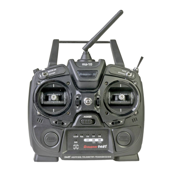
Description of the transmitter Control elements on the transmitter mz-10 Antenna with folding and swivel joint Eyelet for neck strap 2 way switch (Attitude / Rate mode) 3 way switch (FLIP / OFF / LED) Right control stick Arrow key (select video channel) Trims (active in Attitude mode only) On/off switch LED indicators field... -
Page 11: Digital Trim
Digital trim Digital trim with an acoustic feedback The two control sticks have digital trimming. Note The digital trim is active only in the previously mentioned position of the Attitude / Rate mode switch (3) on the upper right part of the transmitter. -
Page 12: Transmitter Back Side
Transmitter back side mz-10 1 Case screws 2 Battery case cover 3 Data socket to connect: - programming connector (region setting + controls mode) - optional SMART BOX - Bluetooth module - Interface adapter to update the transmitter 4 Charge port (to charge an optional available battery) 12 / 32 S1001.G1_sh_V1... -
Page 13: Data Socket
= signal line (orange) = Plus line (red) = Minus line (brown or black) You can find more information about the listed accessories on www.graupner.de. Charging socket This port has to be used only for charging optional available rechargeable batteries. -
Page 14: Commissioning
Commissioning Adjust screws for brake spring and ratchet Neutralization lever Screw to convert from neutralizing to non neutralizing Stick self centering force adjust screws Brake spring and ratchet Opening/closing the transmitter housing The transmitter should be opened only in the following cases: ... -
Page 15: Neutralizing The Control Sticks
CAUTION Never switch the transmitter on while the housing is open! Open step by step: Before opening the housing switch the transmitter off. Open the battery case. Remove the battery box lifting it from one side and gently release it from the velcro tape. Unplug the connector. -
Page 16: Brake Spring And Ratchet
Brake spring and ratchet The outboard screw of the two marked in the figure adjust the braking force. The inboard screw adjusts the strength of the ratchet for the res- pective control stick. Note The right control stick gimbal is specular to the left one, so that here the screws are located right on the top side. -
Page 17: Transmitter Power Supply
Transmitter power supply The mz-10c HoTT transmitter normally includes normally 4 non-rechargeable batteries. Installing the batteries WARNING Alkaline batteries (dry batteries) should not be recharged. Acute risk of explosion! Note Pay attention when inserting the batteries to the correct position and make sure the contacts are solid. -
Page 18: Optional Power Supply With Battery Pack
NiMH batteries. WARNING Follow the safety instructions included with the batteries! Polarity of the mz-10c HoTT charging socket The charging cables available on the market by other manufac- turers frequently have different polarities. For this reason, you should only use original Graupner charging cable. -
Page 19: Led Panel And Keys
LED panel and keys Cut-o Rate BIND -100% +100% 1 MODE buttons 1. Push and hold while switching on the transmitter ..starts the firmware-update ... activates the Fail-safe setting 2. Transmitter switched on: Binding transmitter and receiver short push takes a snapshot through the camera Push for about 2 seconds: select video channel 2 CUT-OFF Red LED blinks: Cut-off function is on... -
Page 20: Binding
Binding Binding the mz-10c transmitter When binding, make sure that the transmitter antenna is always far enough away (1 to 2 meters) from the receiver antenna. Binding step by step: 1. Switch the transmitter on and connect the power supply to the receiver. -
Page 21: Range And Function Test
Range and function test When the range test starts, through contemporaneously pus- hing the left MODE and the right ENTER keys, the transmitter output power decreases significantly, then you can perform a function test in a distance not higher than 100 m. After the 90 second range test, the transmitter switches back to full output, and the signal tone stops. -
Page 22: Range Warning
In case the transmitter cannot set a connection to a proper back channel or during the use an existing connection is interrupted, the transmitter mz-10c BIND LED turns off and the buzzer indicates it with a 4 times beep signal (back channel missing), after that with a 3 times beep following until the transmission interference persists. -
Page 23: Operation And Settings
Operation and settings Transmitter programming CAUTION Switch the receiver off in your copter so that, during the program- ming process of the options described in the following paragraphs, the motors do not start accidentally. Notes Within an activation of the described below rotation procedure for setting the desired locale or control arrangement, however, only one option can always be activated. -
Page 24: Control Mode
Control mode There are four different ways of assigning the four control func- tions of roll, nick, yaw and throttle/pitch of both sticks. The options that are chosen depend on the individual preferences of the model pilot. MODE 1 (Gas/Pitch rechts) MODE 2 (Gas/Pitch links) Nicken Motor / Pitch... -
Page 25: Fail Safe
Fail Safe The "Fail Safe" function determines the response of the receiver both by directly switching on the receiver system and when there is an interruption in transmission from the transmitter to receiver. The functions connected to each receiver outputs can then ... ... - Page 26 Fail-safe variant selection Push and hold the MODE button on the left of the LED panel while switching on the transmitter. Release the button after having switched the transmitter on and power the receiver pre- viously bound to the transmitter. The transmitter BIND LED should then light on yellow.
- Page 27 Fail-Safe OFF With the "OFF" setting, over the course of a malfunction, the receiver stops transmitting control pulses for the relevant servo output The receiver switches the pulse line "off". ATTENTION Verify by selecting "Fail-safe OFF" the reaction of your copter to the switch off of the impulse during the interference.
-
Page 28: Switch Functions
Switch functions Motor stop function Motorsteuerung The motor stop function is active completely independently from the position of this switch, until after switching on the transmit- ter the throttle/pitch stick has not been brought at least once in the motor-OFF position. Motorstopp ATTENTION This function prevents accidental starting of motors, thus reducing... -
Page 29: Firmware Update
Only operate your transmitter using the current software version. these information can also be found at: www.graupner.de => Service & Support => Update and revision history for GRAUPNER HoTT components. Before each update check the transmitter battery charge status. -
Page 30: Transmitter Software Update
5. In the next step it will be asked to switch the transmitter on: push the MODE button on the mz-10c transmitter while you switch it on. Release the MODE button as soon as the trans- mitter has been recognized: "Found target device ...". -
Page 31: Disposal
The cur- poses only and may be changed without prior notice. The cur- rent version can be found on the Internet at www.graupner.de rent version can be found on the Internet at www.graupner.de on the relevant product page.