GRAUPNER mz-32 HoTT Manual
32 channel 2,4 ghz
Hide thumbs
Also See for mz-32 HoTT:
- Manual (49 pages) ,
- Reference manual (42 pages) ,
- Manual (19 pages)
Table of Contents
Advertisement
Quick Links
Advertisement
Table of Contents

Related Manuals for GRAUPNER mz-32 HoTT


Summary of Contents for GRAUPNER mz-32 HoTT
- Page 1 Manual mz-32 HoTT 32 channel 2,4 GHz transmi er No. S1024.77...
- Page 2 2 / 48 S1024.mz32_V1.7_sh_en...
-
Page 3: Table Of Contents
Table of contents Intr ................5 Service centre ................5 Intended use ................6 Target group ..................6 Package content ................ 6 Technical data ................7 Symbol descrip ..............7 Safety notes ................8 For your safety by handling the transmi er ........8 For your safety! Handling the ba ery. - Page 4 Chang Preset ............22 Rename Model................22 Crea ew Model ..............23 Keys to the le ay ............24 Keys to the right of the display .............24 Screen lock ..................24 Output Swap .................24 Symbols in the main display ............25 Receiver Binding ..............26 Bind Group ..................26 Range test ..................27 Digital switch .................28 control and mixer characteris...
-
Page 5: Intr
Intr Thank you for purchasing a Graupner mz-32 HoTT transmi er. To get the most out of your mz-32, read the manual carefully before use and opera If you experience any trouble during opera consult this manual rst or ask assistance from your dealer or Graupner Service Centre. -
Page 6: Intended Use
Package content Transmi er mz-32 HoTT Transmi er display and programming stand USB cable USB adapter for receiver and sensor updates 1s3p LiHV transmi er ba ery with 9000 mAh... -
Page 7: Technical Data
Technical data Transmi er mz-32 HoTT Frequency band 2,4 … 2,4835 GHz Modula FHSS Transmi ower 100 mW EIRP Contr can be trimmed 64 swit Temperature range -10 … +55 °C Antenna 1 linear and 1 circular polarized, with adjustable angle, integrated antenna... -
Page 8: Safety Notes
Safety notes These safety ins are intended not only to protect the prod- uct, but also for your own and other people’s safety. Therefore please very carefully before using the product! Do not leave the packaging material lying around, this could be a dangerous toy for children. -
Page 9: For Your Safety! Handling The Ba Ery
Note During transport, protect the model and the transmi er from dam- ages. For your safe a ery. CAUTION Protect all equipment from dust, dirt, moisture. Only use in dry loca Do not use any damaged ba ery. Any altera ns to the ba ery can cause serious injury or burns. - Page 10 they must be recharged immediately. Deep discharge makes the ba ery short-term, longer storage in discharged as well as fully charged state make the ba ery in the long term useless. 10 / 48 S1024.mz32_V1.7_sh_en...
-
Page 11: Descrip Ransmi Er
Descrip ransmi er Control elements on the transmi er 3 way switch SW 5 2 way switch SW 6 Digital bu on DT7 Foldable transmi er antenna Transmi er handle Digital bu on DT8 3 way switch SW 8, top push-switch, bo om latch- ing-switch 3 way switch SW 7 S1024.mz32_V1.7_sh_en... -
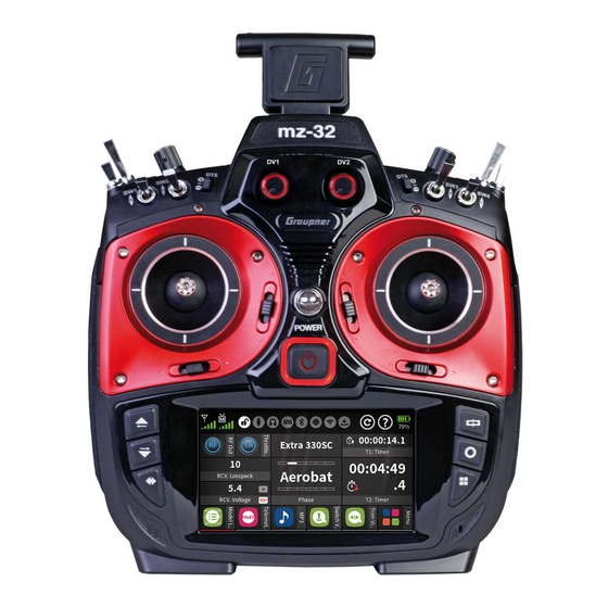
Page 12: Transmi Er Front
Transmi er Front Display Scroll through menu pages Scroll through menu pages Scroll through menu pages Trim bu on of the le control s Le control s 3 way switch SW 1 3 way switch SW 8, 1x push-switch, 2x latching-switch Digital bu on DT5 Digital bu on DT6 3 way switch SW 3... -
Page 13: Transmi Er Backside
Transmi er Backside Ba ery case cover Gimbal tension screw for horizontal contr Gimbal tension screw for v cal control. Lower screw is for tension of the control s rotary control LV2 Inner screw adjusts brake force Outer screw adjusts ratchet's strength Transmi er handle Foldable transmi er antenna over audio, COMM, DATA and DSC c... -
Page 14: Xtures
Charging the transmi er ba ery Note Once connected to a PC or other USB power source, a yellow should be lit solidly to the le of the mz-32 HoTT micro-USB port. If this yellow or is even dark, the power source is too weak to charge the transmi er. - Page 15 The charger should always be supervised during charge and it should be used only in r ed with a smoke detector. Mass storage memory If the mz-32 HoTT transmi er is connected to a compa PC and the "Mass storage" vated by tapping, the memory of the transmi er can be accessed from the PC.
-
Page 16: Transmi Er Prepara
Transmi er prepara Control s Adjus gth of the control s ks Both s ks can be adjusted in length: By holding the lower half and turning the upper part of the knurled handle, the screw is loosened. The control s is extended or shortened by turning it up or down and then xed by screwing each against each other of the upper and lower part of the handle. -
Page 17: Transmi Er Power Supply
Transmi er power supply The mz-32 HoTT transmi er is normally delivered with a 9000 mAh 1s3p LiHV ba ery. Installing the ba ery Note Pay a en when the ba ery to the correct make sure the contacts are solid. Interrup... -
Page 18: St Ransmi Er
Switch on transmi er Pressing the front ON / OFF switch for about 1 second switches the mz-32 HoTT transmi er on. etup of the transmi er If the transmi er is s in the delivery status or the transmi er was previously reset to factory se in the "Info &... - Page 19 (Copter) (Land and water models) Notes The control mode selected during setup of the transmi er is stored as a default for models to be set up in the future. Chang- ing the default mode se can be done in the "Control Mode Preset"...
- Page 20 In this display, the current date and is entered or corrected as etup of the transmi er. step-by-step 1. T This is displayed in white and are displayed at the bo om of the display. 2. Use the " " or central " " bu on to select the desired value. 3.
-
Page 21: Switch O Ransmi Er
Switch o ransmi er Press the front ON / OFF switch and hold it un the "Switch o mes- sage display appears. Tapping "back" stops the process. Touching "OK" switches o the transmi er. Alterna vely, press and hold the ON / OFF switch un ransmi er shuts o . -
Page 22: Change Current S
Change current s The s mode entered as part of the setup of the transmi er is saved as a default in the "System Con menu and will be auto- ma cally used with all models when newly created. You can s change the mode (MODE1, MODE2 …) independently from the system se This can be done in the model types menu... -
Page 23: Crea Ew Model
Crea ew Model Create new model step-by-step 1. Tap the green "Basic" menu tab. 2. Tap the "Model List" icon. 3. Tap the model number in the "No." column. At the bo om of the display a bar with symbols is displayed. 4. -
Page 24: Keys To The Le Ay
Keys to the le Hereina er referred to as upper, center and low keys. These keys are used to scroll through lists, columns, etc., in the same way as their arrow dir Pressing the lower le bu on for about one second switches the i t c t t i i s s... -
Page 25: Symbols In The Main Display
Symbols in the main display 9 10 11 12 13 RF status of the transmi er RF status of the receiver Screen lock on/o USB c connected/not connected Headphones connected/not connected DSC cable connected/not connected Bluetooth on/o GPS signal available/not available WLAN connected/not connected Data logging on/o Widget and data clear icon... -
Page 26: Receiver Binding
Receiver Binding To establish a c with the transmi er, a Graupner HoTT receivers must rst be "bound" to at least one model memory. This process is generally called "binding" and it needs to be repeated ew receiver is installed in a model. -
Page 27: Range Test
Binding procedure step-by-step 1. Move transmi er and receiver at a moderate distance from each 2. Switch on the mz-32 HoTT transmi er without switching on the RF or set the RF Transmission to "OFF" in the "RF Set" of the "RF Set"... -
Page 28: Digital Switch
Never start a range test on the transmi er during normal model opera Digital switch The transmi er mz-32 HoTT features 64 digital switches. These can be found in the “Special” menu and can be de vated and switched in the submenu “Digital Switch”. In... - Page 29 Notes Switching to level allows the direct c of transistors to the receiver output via a series resistor. In Graupner receivers GR-12 GR-16 GR-24 and GR-24 PRO well as series resistors are allready installed and be connected directly between the orange servo pulse wire and the brown or black “-”...
-
Page 30: Se Control And Mixer Characteris
Assign Digital Switches to a widget step-by-step 1. Switch to the submenu “Digital Switch”. 2. Tap on the st “Act” icon to te the Digital Switch and select the desired mode (On/O P 3. Connect for example a servo to the channel you designated as Digital Switch. - Page 31 The horizontal characteris curve can only be moved cally and thus for ex as the basis for speed spec- for speed controllers. 5. If necessary bo om righ in the to the right of “Spline” select whether the characteris should be “square” or “rounded”. Set characteris rve step-by-step 1.
-
Page 32: Calibra
calibra If the center of the self-neutralizing control s does not correspond exactly to 0% control travel, this can be corrected in this menu. step-by-step 1. Change to the “Model list” submenu of the “green” basic menu. ze a free model memory with any model type. 3. -
Page 33: Servo Display
Servo display The Servo View monitor can be called upon at any by pressing the servo monitor key on the right side of the radio. The view represents the of any control or switch including mixers. The default screen shows channel 1 … 16. A swipe from the bo om to the top will rev The default bar chart view shows the channel between... -
Page 34: Telemetry
Telemetry The telemetry c between the transmi er and receiver takes place via the return channel of the HoTT receiver de the main receiver. If more than one receiver is bound to a model memory, the return channel will be by default the last bound receiver. This assignment can be changed in the submenu “RF Set”... -
Page 35: Telemetry Cycle
Telemetry Cycle In those situa where for example two airplane models are about to be operated at close proximity to another controlled by two sep- arate transmi ers you may choose to reduce or eliminate the telem- etry back channel of one of the models to avoid poten interfer- ence. -
Page 36: Setting & Data View
GR-12 or GR-16 can be found in the manual of the receiver model as well as in the manuals of the various other Graupner handheld or tray transmi ers. The apperances may di er depending on the transmi er model but remains the same. - Page 37 upper and low keys Menu lines in which parameters can be changed are indicated by a preceding angle bracket ( ). Tapping on the lower or upper on moves this " " pointer one line down or up. Lines which cannot be navigated to cannot be changed. middle "ENTER"...
-
Page 38: Digital Switch
“Opera and menu ”, the transmi er mz-32 HoTT over 64 digital switches. Details can be found in the men On the receiver side, these digital switches can be assigned to the vely desired switching channel both in the submenu “RF Con .”... - Page 39 S1024.mz32_V1.7_sh_en 39 / 48...
-
Page 40: Firmware Update
Only operate your transmi er using the current ware ver- sion. Copy from mass storage step-by-step 1. Connect the mz-32 HoTT transmi er to a Windows PC or laptop via the rear micro-USB port. 2. Switch on the transmi er. 3. Select "Mass storage" in the aut cally displayed display. - Page 41 Inst step-by-step 1. Connect the mz-32 HoTT transmi er to a Windows PC or laptop via the rear micro-USB port. 2. Switch on the transmi er. 3. Select "Mass storage" in the aut cally displayed display. 4. Start the program "Firmware_Upgrade_gr_Studio" on the PC or laptop.
-
Page 42: Forced Update
4. As described above in points 1 to 9 under the transmit- ter step-by-st load a suitable for the mz-32 HoTT transmi er onto the transmi er. 5. Switch the transmi er by pressing the central ON / OFF switch 6. Disconnect from PC or laptop. - Page 43 S1024.mz32_V1.7_sh_en 43 / 48...
- Page 44 44 / 48 S1024.mz32_V1.7_sh_en...
- Page 45 S1024.mz32_V1.7_sh_en 45 / 48...
-
Page 46: Simplified Declaration Of Conformity
Manufaturer / Manufakturer GRAUPNER Co. Ltd Post Code: 14557 202-809, 18, Bucheon-ro 198beon-gil, Bucheon-si, Gyeonggi-do, South Korea Vertrieb Deutschland, Österreich, Niederlande D-Power Modellbau Robbe Modellsport Inhaber: Horst Derkum Sürther Straße 92-94 Industriestraße 10 50996 Köln 4565 Inzersdorf im Kremstal Deutschland Österreich... -
Page 47: Notes On Environmental Prot
The current version can be found on the Internet at www.graupner.com on the relevant product page. In the company Graupner has no responsibility or liability for any errors or inaccuracies that may ap- pear in cons Not liable for prin rors.
Need help?
Do you have a question about the mz-32 HoTT and is the answer not in the manual?
Questions and answers
After you set the switches at their desired position, how do you set up a lever to set them all at the settings you set up?
To set up a lever to adjust the switches on the GRAUPNER mz-32 after positioning them:
1. Place all switches in the desired start positions.
2. If you also want to store the lever (LV/DV) positions, move them to the desired positions.
3. Activate the value icon on the notice dialog to store lever positions.
4. Tap on "Store" to save the switch and lever positions.
When turning on the transmitter, it will notify you if a switch is not in its stored start position. You can adjust the switches or press "Pass" to continue.
This answer is automatically generated
how to set up combi switches
To set up Combi Switches on the GRAUPNER mz-32 HoTT:
1. Position each switch (Input Control) in the desired condition.
2. Tap on the Store field to save the setting.
3. If the saved condition is met, the Output icon will turn orange, indicating an On condition for the Combi Switch.
You do not need to assign inputs for all four controls.
This answer is automatically generated