Sign In
Upload
Download
Table of Contents
Contents
Add to my manuals
Delete from my manuals
Share
URL of this page:
HTML Link:
Bookmark this page
Add
Manual will be automatically added to "My Manuals"
Print this page
×
Bookmark added
×
Added to my manuals
Manuals
Brands
GRAUPNER Manuals
Transmitter
mz-32 HoTT
Manual
GRAUPNER mz-32 Manual
16 channel digital switch module
Hide thumbs
Also See for mz-32
:
Manual
(49 pages)
,
Reference manual
(42 pages)
,
Manual
(48 pages)
1
2
Table Of Contents
3
4
5
6
7
8
9
10
11
12
13
14
15
16
17
18
19
page
of
19
Go
/
19
Contents
Table of Contents
Bookmarks
Table of Contents
Table of Contents
Personal Notes
Introduction
Service Centre
Intended Use
Package Content
Declaration of Conformity
Technical Data
Description
Symbol Description
Safety Notes
Installing the Module
Setting the Electric Connections
Connection Diagram
Note on Use of Switch Relais
Programming of Receiver and Digital Switches
Naming the Digital Switches
Mode of a Digital Switch
Arranging the Digital Switches
Using Multiple Switch Modules
Firmware Update
Notes on Environmental Protection
Care and Maintenance
Warranty Conditions
Advertisement
Quick Links
1
Table of Contents
2
Introduction
3
Package Content
4
Technical Data
5
Description
6
Installing the Module
7
Setting the Electric Connections
Download this manual
See also:
Reference Manual
,
Manual
Manual
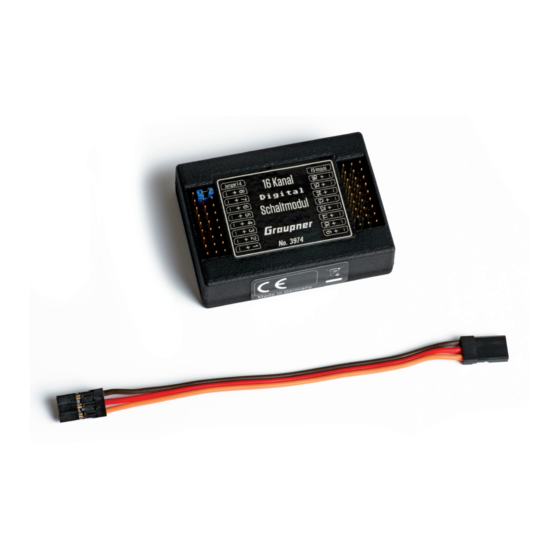
16 channel digital switch module
SumD V3 capable matching mz-16 / mz-32 / mc-16 Expert / mc-32 Expert
No. 3974
Table of
Contents
Previous
Page
Next
Page
1
2
3
4
5
Advertisement
Table of Contents
Need help?
Do you have a question about the mz-32 and is the answer not in the manual?
Ask a question
Questions and answers
Related Manuals for GRAUPNER mz-32
Remote Control GRAUPNER S1024 Reference Manual
2.4 ghz transmitter (51 pages)
Transmitter GRAUPNER mz-32 HoTT Manual
32 channel 2.4 ghz transmitter (49 pages)
Transmitter GRAUPNER mz-32 HoTT Manual
32 channel 2,4 ghz (48 pages)
Remote Control GRAUPNER mz-32 HoTT Reference Manual
32 channel 2.4 ghz transmitter (42 pages)
Transmitter GRAUPNER S1047 Manual
16 channel 2.4 ghz transmitter (52 pages)
Transmitter GRAUPNER mz-16 HoTT Manual
16 channel 2.4 ghz transmitter (48 pages)
Transmitter GRAUPNER mz-10 HoTT S1001 User Manual
(40 pages)
Transmitter graupner mz-10 HoTT Manual
6 channel 2,4 ghz transmitter (48 pages)
Transmitter GRAUPNER mc-32 Programming Manual
(324 pages)
Transmitter GRAUPNER mz-24 PRO Manual
12 channel hott 2.4 ghz transmitter (34 pages)
Transmitter GRAUPNER mc-28 Programming Manual
16 channel hott 2,4 ghz transmitter (80 pages)
Transmitter GRAUPNER mc-28 Manual
16 channel hott 2,4 ghz transmitter (40 pages)
Transmitter GRAUPNER mz-12PRO HoTT Manual
12 channel 2,4 ghz transmitter (36 pages)
Transmitter GRAUPNER mc-16 Expert Manual
16 channel digital switch module (19 pages)
Transmitter GRAUPNER mz-10c Manual
Hott 2,4 ghz transmitter for copter (32 pages)
Transmitter GRAUPNER mc-19 tiFS Manual
(16 pages)
This manual is also suitable for:
Mz-16
Mc-32 expert
Mc-16 expert
Table of Contents
Print
Rename the bookmark
Delete bookmark?
Delete from my manuals?
Login
Sign In
OR
Sign in with Facebook
Sign in with Google
Upload manual
Upload from disk
Upload from URL


Need help?
Do you have a question about the mz-32 and is the answer not in the manual?
Questions and answers