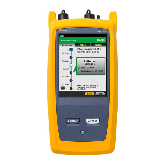
Fluke CertiFiber Pro User Manual

Fluke CertiFiber Pro User Manual

Optical loss test set
Hide thumbs Also See for CertiFiber Pro:
Table of Contents

Advertisement

CertiFiber
Pro
®
Optical Loss Test Set
Users Manual
May 2013 (English)
©2013 Fluke Corporation
All product names are trademarks of their respective companies.

Advertisement

Table of Contents
loading
Need help?

Need help?

Do you have a question about the CertiFiber Pro and is the answer not in the manual?

Questions and answers

Summary of Contents for Fluke CertiFiber Pro

  • Page 1 CertiFiber ® Optical Loss Test Set Users Manual May 2013 (English) ©2013 Fluke Corporation All product names are trademarks of their respective companies.
  • Page 2 The warranty extends only to the original buyer or end user customer of a Fluke Networks authorized reseller, and does not apply to any product which, in Fluke Networks’...
  • Page 3: Table Of Contents

    Contents Chapter 1 Get Acquainted Overview of the CertiFiber Pro Optical Loss  Test Set Modules .............1 Contact Fluke Networks ..........2 Register Your Product ............2 Technical Reference Handbook ........3 Additional Resources ............3 Supplements and Updated Manuals ......3 Kit Contents ..............3 CFP-100-M Kit ............4...
  • Page 4 About LinkWare and LinkWare Stats Software ... 31 Chapter 2 How to Clean Fiber Endfaces How to Use a Fluke Networks IBC OneClick Cleaner ... 36 How to Use Wipes, Swabs, and Solvent ......38 To Clean Bulkhead Connectors ....... 38 To Clean the Optical Connectors on the Modules .
  • Page 5 Contents Step 2: Measure the Loss of the Test  Reference Cords You Will Add ........59 Step 3: Do an Autotest in Smart Remote Mode ..60 Autotest Results for Smart Remote Mode ....61 Fiber IDs for Saved Results in Smart  Remote Mode ............61 Autotest in Loopback Mode ..........64 Step 1: Set the Reference in Loopback Mode ..66...
  • Page 6 CertiFiber Pro Fiber Optical Loss Test Set Users Manual How to Control the Light Source ........97 Use the Display to Control the Main  Tester’s Light Source ..........98 Use the Module’s Button to Control the  Light Source ............. 98...
  • Page 7 Contents See Information About the Tester .........123 Update the Software ............123  Extend the Life of the Battery ........128 Store the Tester ...............128 Remove the Battery ............128 Calibration ...............129 If the Tester Does Not Operate as Usual .......129 Options and Accessories ..........130 Certifications and Compliance ........131 Regulatory Information ..........131 Appendix A: Reference Method Names...
  • Page 8 CertiFiber Pro Fiber Optical Loss Test Set Users Manual...
  • Page 9 (CFP-QUAD module shown) ........... 10 Remote Tester Connectors, Keys, and LEDs  (CFP-QUAD module shown) ........... 12 The Home Screen for CertiFiber Pro Modules....15 LEDs Show the Remote’s Battery Status......19 Connections to See the Status of the Remote’s ...
  • Page 10 CertiFiber Pro Fiber Optical Loss Test Set Users Manual Result for Smart Remote Mode (Unsaved  Bi-Directional Results Shown) .........62 Equipment for Autotests in Loopback Mode....65 Connections for Loopback Mode (1 Jumper Reference, Multimode Fiber)......67 Result for Loopback Mode ..........70 Equipment for Autotests in Far End Source Mode ..73...
  • Page 11: Chapter 1 Get Acquainted

    Chapter 1: Get Acquainted Overview of the CertiFiber Pro Optical Loss Test Set Modules ® The Fluke Networks CertiFiber Pro Optical Loss Test Set (OLTS) ™ modules attach to Versiv main and remote units to make rugged, hand-held testers that let you certify, troubleshoot, and document optical fiber cabling installations.
  • Page 12: Contact Fluke Networks

    Visit our website for a complete list of phone numbers. Register Your Product Registering your product with Fluke Networks gives you access to valuable information on product updates, troubleshooting tips, and other support services. To register, fill out the online registration form on the Fluke Networks website at www.flukenetworks.com.
  • Page 13: Technical Reference Handbook

    To see if a supplement or updated manual is available, log on to www.flukenetworks.com, click SUPPORT > Manuals, then select a product. Kit Contents The CertiFiber Pro kits come with the accessories in the lists below. If something is damaged or missing, contact the place of purchase immediately.
  • Page 14: Cfp-100-M Kit

    CFP-100-M Kit Versiv main and remote units with battery packs  Two CertiFiber Pro Multimode Optical Loss Test Set (OLTS)  Modules for tests at 850 nm and 1300 nm Two encircled flux test reference cords (EF-TRCs) for 50 µm/ ...
  • Page 15: Cfp-100-Q Kit

    CFP-100-Q Kit Versiv main and remote units with battery packs  Two CertiFiber Pro Quad Optical Loss Test Set (OLTS) Modules  for tests at 850 nm, 1300 nm, 1310 nm and 1550 nm Two encircled flux test reference cords (EF-TRCs) for 50 µm/ ...
  • Page 16: Cfp-Q-Add Kit

    CertiFiber Pro Fiber Optical Loss Test Set Users Manual CFP-Q-ADD Kit Two CertiFiber Pro Quad Optical Loss Test Set (OLTS) Modules  for tests at 850 nm, 1300 nm, 1310 nm and 1550 nm Two encircled flux test reference cords (EF-TRCs) for 50 µm/ ...
  • Page 17: Safety Information

    To prevent possible fire, electric shock, or personal injury:  Use only AC adapters approved by Fluke Networks for use with the tester to supply power to the tester and charge the battery. Do not put the battery pack in a fire or an ...
  • Page 18 CertiFiber Pro Fiber Optical Loss Test Set Users Manual If this equipment is used in a manner not specified  by the manufacturer, the protection provided by the equipment can possibly be impaired.   Warning: Class 1 and Class 2 Laser Products...
  • Page 19 You can lose a USB flash drive, cause damage to it,  or accidentally erase the contents of the drive. Thus, Fluke Networks recommends that you save no more than one day of test results on a flash drive.
  • Page 20: Connectors, Keys, And Leds

    CertiFiber Pro Fiber Optical Loss Test Set Users Manual Connectors, Keys, and LEDs  GPU123.EPS Figure 1. Main Tester Connectors, Keys, and LEDs (CFP-QUAD module shown)  LCD display with touchscreen Singlemode output port with removable connector adapter  and dust cap. This port transmits optical signals for loss and...
  • Page 21 Chapter 1: Get Acquainted Connectors, Keys, and LEDs The LED below the output port is red when the port transmits 1310 nm and green for 1550 nm.  Input port with removable connector adapter and dust cap. This port receives optical signals for loss, length, and power measurements.
  • Page 22 CertiFiber Pro Fiber Optical Loss Test Set Users Manual Decal with laser safety  information.  GPU136.EPS Figure 2. Remote Tester Connectors, Keys, and LEDs (CFP-QUAD module shown)
  • Page 23 Chapter 1: Get Acquainted Connectors, Keys, and LEDs  PASS LED comes on when a test passes. TEST LED comes on during a test. FAIL LED comes on when a test fails. TALK LED comes on when the talk function is on. LOW BATTERY LED comes on when the battery is low.
  • Page 24 CertiFiber Pro Fiber Optical Loss Test Set Users Manual  : Starts a test.  : Power key  : Press  to use the headset to speak to the person at the other end of the link. Press again to adjust the volume. To turn off the talk function, hold down .
  • Page 25: The Home Screen For Certifiber Pro Modules

    The home screen (Figure 3) shows important test settings. Before you do a test, make sure these settings are correct. GPU117.EPS Figure 3. The Home Screen for CertiFiber Pro Modules PROJECT: The project contains the settings for a job and helps ...
  • Page 26 CertiFiber Pro Fiber Optical Loss Test Set Users Manual Shows a summary of the test results in the project:  The number of tests that passed. The number of tests that failed. The test setup panel shows the settings the tester will use when ...
  • Page 27  This icon shows when the input and output ports on the tester’s CertiFiber Pro module are connected to the ports on the remote’s CertiFiber Pro module and the remote tester is turned This icon shows when the talk function is on. To use the talk ...
  • Page 28: Ac Adapter And Battery

    CertiFiber Pro Fiber Optical Loss Test Set Users Manual AC Adapter and Battery You can use the AC adapter (model VERSIV-ACUN) or the lithium ion battery (model VERSIV-BATTERY) to supply power to the tester. To remove the battery, see “Remove the Battery” on page 128.
  • Page 29 Chapter 1: Get Acquainted AC Adapter and Battery If the AC adapter is not connected, the red bar shows that the battery is very low. Connect the AC adapter to charge the battery and make sure the tester continues to operate. The red bar also shows if the AC adapter is connected, but the battery is not installed.
  • Page 30 CertiFiber Pro Fiber Optical Loss Test Set Users Manual To see more information about the battery status Make the connections shown in Figure 5 and turn on both testers. Tap TOOLS, then tap Battery Status. When the AC adapter is not connected, the screen shows the Time Remaining, which is the approximate battery life at the present rate of use.
  • Page 31: How To Use The Touchscreen

    Chapter 1: Get Acquainted How to Use the Touchscreen How to Use the Touchscreen The touchscreen lets you use fingertip gestures to control the tester. You can also operate the touchscreen with a stylus that is made for projected capacitance touchscreens. ...
  • Page 32 CertiFiber Pro Fiber Optical Loss Test Set Users Manual To move the image, drag it in To zoom in, use the reverse- any direction. pinch gesture To quickly go back to 1:1 To zoom out, use the pinch magnification, double-tap the gesture screen.
  • Page 33: Verify Operation

    Chapter 1: Get Acquainted Verify Operation Verify Operation The tester does a self test when you turn it on. If the tester shows an error or does not turn on, refer to “If the Tester Does Not Operate as Usual” on page 129. Change the Language On the home screen, tap the TOOLS icon, tap Language, then tap a language.
  • Page 34 CertiFiber Pro Fiber Optical Loss Test Set Users Manual HGD40.EPS Figure 7. FIX LATER, TEST AGAIN, and TEST Buttons and the TEST Key SAVE (yellow), TEST (gray): These buttons show if the test   passed and Auto Save is off. When you tap SAVE, you can save the results with an ID that you make or select.
  • Page 35: Overview Of Memory Functions

    Chapter 1: Get Acquainted Overview of Memory Functions TEST AGAIN: This button shows if the test failed. Tap this button  to do the test again for the same ID. If Auto Save is on, the tester saves subsequent results with the same ID. If Auto Save is off, you can save the result if necessary.
  • Page 36: Options For Cable Ids

    CertiFiber Pro Fiber Optical Loss Test Set Users Manual Options for Cable IDs When you save the test results for a cable, you usually give the results the name that is the ID for the cable. There are several methods you can use to make IDs for test results: You can use the CABLE ID SETUP screen to make a set of ...
  • Page 37: How To Remove And Install The Connector Adapters

    Chapter 1: Get Acquainted How to Remove and Install the Connector Adapters To turn the Auto Save function on or off On the home screen, tap the Next ID panel. On the CHANGE ID screen, tap the On/Off control next to Auto Save.
  • Page 38 CertiFiber Pro Fiber Optical Loss Test Set Users Manual  Caution Turn only the collar on the adapter. Do not use tools to remove or install the adapters.  Caution Do not touch the photodiode lens. Slot Put the key into the slot before you turn the collar on the adapter.
  • Page 39: How To Install A Strap

    Chapter 1: Get Acquainted How to Install a Strap How to Install a Strap Two types of straps are available for the tester: a hand strap that helps you hold the tester, and an optional carrying strap that lets you carry and hang the tester. Figure 9 shows how to install a strap and how to use the hand strap.
  • Page 40 CertiFiber Pro Fiber Optical Loss Test Set Users Manual Removal Installation  Caution To prevent damage to the case,  push the latches down (  before you turn them ( HGD20.EPS Figure 10. How to Remove and Install a Module...
  • Page 41: About Linkware And Linkware Stats Software

    Updates to LinkWare software are available on the Fluke Networks website. The LinkWare Stats Statistical Report software that is included with LinkWare software provides statistical analysis of cable test reports and generates browsable, graphical reports.
  • Page 42 CertiFiber Pro Fiber Optical Loss Test Set Users Manual...
  • Page 43: Chapter 2 How To Clean Fiber Endfaces

    Chapter 2: How to Clean Fiber Endfaces When a fiber optic link does not operate correctly, the cause is frequently a dirty endface in a connector. Figure 11 shows examples of dirty endfaces and an endface that has been correctly cleaned and polished.
  • Page 44 Always clean and inspect the endfaces in fiber connectors before you make connections. Fluke Networks recommends that you use a mechanical device, such as the Fluke Networks IBC OneClick Cleaner, to clean connectors. If you do not have such a device, or if the device does not clean the connector sufficiently, use other optical-grade supplies to clean connectors.
  • Page 45 Chapter 2: How to Clean Fiber Endfaces GPU49.EPS   Versiv main unit with CertiFiber Fiber cleaning supplies Pro module installed  AC adapter with line cord  Video probe with USB connector (optional) (DI-1000 shown) Figure 12. Equipment to Clean and Inspect Fiber Endfaces...
  • Page 46: How To Use A Fluke Networks Ibc Oneclick Cleaner

    CertiFiber Pro Fiber Optical Loss Test Set Users Manual How to Use a Fluke Networks IBC OneClick Cleaner  Caution To prevent damage to the device and to connectors and to keep contamination off of endfaces, read all instructions and obey all safety precautions given in the instructions for the device you use to clean connectors.
  • Page 47 Chapter 2: How to Clean Fiber Endfaces How to Use a Fluke Networks IBC OneClick Cleaner CLICK! CLICK! GPU16.EPS Figure 13. How to Use the IBC OneClick Cleaner...
  • Page 48: How To Use Wipes, Swabs, And Solvent

    CertiFiber Pro Fiber Optical Loss Test Set Users Manual How to Use Wipes, Swabs, and Solvent  Caution To prevent damage to connectors and to keep contamination off of endfaces: Always discard wipes or swabs after you use them. ...
  • Page 49: To Clean The Optical Connectors On The Modules

    Chapter 2: How to Clean Fiber Endfaces How to Use Wipes, Swabs, and Solvent To Clean the Optical Connectors on the Modules To clean the optical connectors on the modules, first use the procedure given under “To Clean Bulkhead Connectors”. If a connector is very dirty or the procedure above does not make it clean, use this procedure: Unscrew the adapter on the connector.
  • Page 50 CertiFiber Pro Fiber Optical Loss Test Set Users Manual...
  • Page 51: Chapter 3 How To Certify Fiber Cabling

    44 and “About Standard Mandrels” on page 47. Keep the tester’s software current. The latest software is  available on the Fluke Networks website. See “Update the Software” on page 123.  Make sure you select the correct fiber type and test limit for the job, and the index of refraction for the fiber is correct.
  • Page 52: About The Reference For Fiber Tests

    Let them sit longer if they are above or below ambient temperature. The tester requires you to set the reference at these times: When you change the CertiFiber Pro module in the main or  remote tester. When you use a different remote tester.
  • Page 53: Good Reference Values

    Chapter 3: How to Certify Fiber Cabling Requirements for Reliable Fiber Test Results When a loss measurement is negative. This occurs when there  was a problem when you set the reference. For example, an endface was dirty or the testers were cold. ...
  • Page 54: How To See The Reference Values

    The CFP-MM and CFP-QUAD kits includes the EF-TRC (encircled flux test reference cords), which have signal conditioners on the cords. When you use the EF-TRCs with the CertiFiber Pro multimode modules, your tester complies with IEC 61280-4-1, ISO/ IEC 14763-3, and TIA-526-14-B standards for encircled flux.
  • Page 55 To prevent damage to fiber connectors, to prevent data loss, and to make sure that your test results are as accurate as possible: Use the EF-TRC cords only with the CertiFiber Pro  modules or with sources approved by Fluke Networks for use with the cords.
  • Page 56: About Apc Connectors

    CertiFiber Pro Fiber Optical Loss Test Set Users Manual Minimum bend diameter: 1.2 in (30 mm) GPU157.EPS Figure 14. How to Prevent Damage to the EF-TRC Fiber Cables About APC Connectors When you do tests on links with APC (angled physical contact) connectors, use only test reference cords with APC connectors on the ends connected to the link.
  • Page 57: About Standard Mandrels

    Standard mandrels make measurements of multimode power loss more reliable than if you use no mandrels, but the measurements do not comply with the standards for encircled flux. Fluke Networks recommends that you always use only the EF-TRCs with the CertiFiber Pro multimode modules so that your measurements comply with EF standards.
  • Page 58: Settings For Fiber Tests

    CertiFiber Pro Fiber Optical Loss Test Set Users Manual Settings for Fiber Tests Table 2 gives descriptions of the settings for fiber tests. To set up a project, which includes the settings in Table 2, cable IDs, and operator names, see Chapter 8.
  • Page 59 Table 2. Settings for Fiber Tests Setting Description Module Select the CertiFiber Pro module you will use. Test Type Use Smart Remote mode for tests on duplex-fiber cabling. See page 55. Use Loopback mode for tests on patch cords and cable spools.
  • Page 60 CertiFiber Pro Fiber Optical Loss Test Set Users Manual Table 2. Settings for Fiber Tests (continued) Reference On the No. of Connectors/Splices screen, set the number Method of jumpers you will use in each fiber path when you set the reference. The dotted lines in the diagram on the screen show you which parts of the link are included in the test results.
  • Page 61 Note The CertiFiber Pro automatically adjusts the number of connections for the Reference Method you use. This is different from the DTX CableAnalyzer, where you do not include the reference connections in the number of connectors.
  • Page 62 CertiFiber Pro Fiber Optical Loss Test Set Users Manual GPU140.EPS Figure 15. Screen to Set the Number of Connectors, Splices, and Jumpers  Total Connections: Enter the total number of connections that are in each path of the link. Do not adjust the number for the Reference Method you use.
  • Page 63 Chapter 3: How to Certify Fiber Cabling Settings for Fiber Tests Jumper Reference Enter the number of jumpers you will use in  each fiber path when you set the reference. The dotted lines in the diagram on the screen show you which parts of the link are included in the test results.
  • Page 64 CertiFiber Pro Fiber Optical Loss Test Set Users Manual Connector or connection = 1 connector pair Connector Splice Connectors included in the test results for the 1 Jumper reference Connector method Connector Reference Test connections connections Total Connections: 3 ...
  • Page 65: About 1 Jumper Reference Connections

    Chapter 3: How to Certify Fiber Cabling About 1 Jumper Reference Connections About 1 Jumper Reference Connections The reference and test connections shown in this manual give 1 jumper results. 1 jumper results include the loss of the fiber plus the loss of the connections at both ends of the link.
  • Page 66 CertiFiber Pro Fiber Optical Loss Test Set Users Manual GPU128.EPS   Main and remote Versiv units Fiber cleaning supplies with CertiFiber Pro modules  Video probe with USB connector installed (DI-1000 shown)  For multimode fiber: two EF-TRC ...
  • Page 67: Step 1: Set The Reference In Smart Remote Mode

    To only set the reference, and not measure the loss of your test reference cords, tap SKIP WIZARD on the SET REFERENCE screen. Fluke Networks recommends that you measure the loss of your test reference cords each time you set the reference.
  • Page 68 CertiFiber Pro Fiber Optical Loss Test Set Users Manual  Caution Do not disconnect the outputs ( ) after you set the reference. When you use the EF-TRCs,  DO NOT use other mandrels. Test reference cord Fiber link Test...
  • Page 69: Step 2: Measure The Loss Of The Test Reference Cords You Will Add

    Chapter 3: How to Certify Fiber Cabling Autotest in Smart Remote Mode To enter the length of the test reference cords you will add to connect to the link, tap TRC LENGTH on the SET REFERENCE screen. The length you enter does not change the test results. The tester saves the length with the results to meet TIA reporting requirements.
  • Page 70: Step 3: Do An Autotest In Smart Remote Mode

    CertiFiber Pro Fiber Optical Loss Test Set Users Manual Step 3: Do an Autotest in Smart Remote Mode  Caution If you disconnected a test reference cord from the output of the tester or remote, you must set the reference again to make sure your measurements are reliable.
  • Page 71: Autotest Results For Smart Remote Mode

    Chapter 3: How to Certify Fiber Cabling Autotest in Smart Remote Mode Save the result: If Auto Save is on, the tester uses the next two IDs to save  the results for the two fibers. If Auto Save is off, tap SAVE if the test passed or FIX ...
  • Page 72 CertiFiber Pro Fiber Optical Loss Test Set Users Manual GPU118.EPS Figure 19. Result for Smart Remote Mode (Unsaved Bi-Directional Results Shown)  The overall result for the Autotest. The fiber IDs and the loss and length measurements for the ...
  • Page 73 Chapter 3: How to Certify Fiber Cabling Autotest in Smart Remote Mode To see the results, limits, and margins for a fiber, tap the window.  The settings the tester used for the test.  The dashed lines are around the connectors and fiber that are included in the loss and length results.
  • Page 74: Autotest In Loopback Mode

    CertiFiber Pro Fiber Optical Loss Test Set Users Manual Autotest in Loopback Mode Use Loopback mode to do tests on spools of cable and segments of uninstalled cable. In this mode, the tester measures loss and length at two wavelengths. If you turn on the Bi-Directional function, the tester makes measurements in both directions.
  • Page 75 Chapter 3: How to Certify Fiber Cabling Autotest in Loopback Mode GPU129EPS   Main Versiv unit with CertiFiber Fiber cleaning supplies Pro module installed  Video probe with USB connector  For multimode fiber: one EF-TRC (DI-1000 shown) test reference cord ...
  • Page 76: Step 1: Set The Reference In Loopback Mode

    CertiFiber Pro Fiber Optical Loss Test Set Users Manual Step 1: Set the Reference in Loopback Mode Turn on the tester and let it sit for a minimum of 5 minutes. Let it sit longer if it is above or below ambient temperature.
  • Page 77 Chapter 3: How to Certify Fiber Cabling Autotest in Loopback Mode  Caution Do not disconnect the Fiber output ( ) after you set the reference. When you use the EF-TRCs,  DO NOT use other mandrels. Test reference cord Reference TRC Verification Fiber Test...
  • Page 78: Step 2: Measure The Loss Of The Test Reference Cord You Will Add

    CertiFiber Pro Fiber Optical Loss Test Set Users Manual To enter the length of the test reference cord you will add to connect to the fiber under test, tap TRC LENGTH on the SET REFERENCE screen. The length you enter does not change the test results.
  • Page 79: Step 3: Do An Autotest In Loopback Mode

    Chapter 3: How to Certify Fiber Cabling Autotest in Loopback Mode Step 3: Do an Autotest in Loopback Mode  Caution If you disconnected the test reference cord from the output of the tester, you must set the reference again to make sure your measurements are reliable.
  • Page 80: Autotest Results For Loopback Mode

    CertiFiber Pro Fiber Optical Loss Test Set Users Manual Autotest Results for Loopback Mode Figure 22 shows an example of Autotest results for Loopback mode. GPU119.EPS Figure 22. Result for Loopback Mode The overall result for the Autotest.  The loss and length measurements for the fiber: ...
  • Page 81 Chapter 3: How to Certify Fiber Cabling Autotest in Loopback Mode To see the results, limits, and margins for the fiber, tap the window.  The settings the tester used for the test.  The dashed lines are around the connectors and fiber that are included in the loss and length results.
  • Page 82: Autotest In Far End Source Mode

    Autotest in Far End Source Mode Use Far End Source mode to measure loss at two wavelengths on one fiber. In this mode, you can use the CertiFiber Pro remote or another source, such as the Fluke Networks SimpliFiber ®...
  • Page 83 Chapter 3: How to Certify Fiber Cabling Autotest in Far End Source Mode GPU130.EPS   Main and remote Versiv units Fiber cleaning supplies with CertiFiber Pro modules  Video probe with USB connector installed (DI-1000 shown)  For multimode fiber: one EF-TRC ...
  • Page 84: Step 1: Set The Reference In Far End Source Mode

    Clean and inspect the connectors on the tester, source, and test reference cords. On the home screen tap SET REF. In the TEST MODE window, select Auto CertiFiber Pro or the type of source you will use, then tap DONE. On the SET REFERENCE screen, tap RUN WIZARD.
  • Page 85 When you set the reference, keep the fiber as straight as possible. Turn on the optical source. On the CertiFiber Pro remote module, hold down the button adjacent to the VFL port for 3 seconds to turn on the multimode source.
  • Page 86 CertiFiber Pro Fiber Optical Loss Test Set Users Manual  Caution Do not disconnect the output ( ) after you set the reference. When you use the EF-TRCs,  DO NOT use other mandrels. EF-TRC* EF-TRC* EF-TRC* Fiber Test reference...
  • Page 87: Step 2: Measure The Loss Of The Test Reference Cord You Will Add

    Chapter 3: How to Certify Fiber Cabling Autotest in Far End Source Mode Step 2: Measure the Loss of the Test Reference Cord You Will Add  Caution If you disconnected the test reference cord from the output of the tester, you must set the reference again to make sure your measurements are reliable.
  • Page 88: Autotest Results For Far End Source Mode

    CertiFiber Pro Fiber Optical Loss Test Set Users Manual On the SET REFERENCE, when the set reference or TRC verification procedure is completed, tap NEXT to see how to connect to the fiber under test. Clean and inspect the all connectors.
  • Page 89 Chapter 3: How to Certify Fiber Cabling Autotest in Far End Source Mode GPU120.EPS Figure 25. Result for Far End Source Mode The overall result for the Autotest.  The loss and length measurements for the fiber:  The result exceeds the limit. The result is within the limit.
  • Page 90: Bi-Directional Tests

    CertiFiber Pro Fiber Optical Loss Test Set Users Manual The dashed lines are around the connectors and fiber that are  included in the loss and length results. Gray connectors and fibers are not included because you used them to set the reference.
  • Page 91 Chapter 3: How to Certify Fiber Cabling Bi-Directional Tests Do an Autotest. Halfway through the test, the tester tells you to switch the input and output fibers.  Caution Switch the connections at both ends of the patch panel or fiber under test, not at the tester's and remote’s ports.
  • Page 92 CertiFiber Pro Fiber Optical Loss Test Set Users Manual...
  • Page 93: Chapter 4 The Fiberinspector Test

    Chapter 4: The FiberInspector Test The optional DI-1000 video probe connects to the type A USB port on the Versiv main unit to let you inspect the endfaces in fiber optic connectors. The probe lets you see dirt, scratches, and other defects that can cause unsatisfactory performance or failures in fiber optic networks.
  • Page 94 CertiFiber Pro Fiber Optical Loss Test Set Users Manual To do the FiberInspector test Connect the probe to the type A USB port on the side of the tester. Make sure the correct tip is on the probe. Clean the connector that you will inspect.
  • Page 95 Chapter 4: The FiberInspector Test How to Do the FiberInspector Test Insert the probe into the connector. To adjust the focus, turn the knob on the probe clockwise or counterclockwise. Note The button on the DI-1000 probe has no function when you use the probe with the Versiv unit.
  • Page 96 CertiFiber Pro Fiber Optical Loss Test Set Users Manual GPU25.EPS Figure 27. FiberInspector Image with Measurement Scales (fiber with 50 µm core shown) Note To see the buttons for the measurement axes and core scales and to change the magnification of the...
  • Page 97 Chapter 4: The FiberInspector Test How to Do the FiberInspector Test To show the scales, tap SCALE ON (  Outer, blue ring: 250 µm cladding  Middle, green rings: 120 µm and 130 µm   Inner, yellow rings: 25 µm and 62.5 µm (to change the size, tap NEXT SCALE) To adjust the brightness or contrast of the image, tap , then...
  • Page 98 CertiFiber Pro Fiber Optical Loss Test Set Users Manual...
  • Page 99: Chapter 5 The Visual Fault Locator

    Chapter 5: The Visual Fault Locator Visual Fault Locator Applications The CertiFiber Pro modules include a visual fault locator that sends a red light down the fiber. The red light shows at the end of the fiber and at breaks, cracks, and sharp bends along the fiber.
  • Page 100: How To Use The Vfl

    CertiFiber Pro Fiber Optical Loss Test Set Users Manual How to Use the VFL Figure 28 shows the equipment for tests with the visual fault locator. GPU137.EPS   Versiv main unit with CertiFiber Video probe with USB connector Pro module installed (DI-1000 shown) ...
  • Page 101 Chapter 5: The Visual Fault Locator How to Use the VFL To use the visual fault locator Note You can connect the visual fault locator to connectors that have 2.5 mm ferrules (SC, ST, or FC). To connect to other ferrule sizes, use a test reference cord with the correct connector at one end and a SC, ST, or FC connector at the tester end.
  • Page 102 CertiFiber Pro Fiber Optical Loss Test Set Users Manual Verify continuity and identify fibers VFL connector VFL button Find microbends and broken fibers Find connectors that have broken fibers inside 1 Press the VFL button: VFL is on (CW, continuous wave).
  • Page 103: How To Monitor Power And Loss

    Chapter 6: The Power Meter and Light Source You can use the CertiFiber Pro main tester to monitor and save measurements of optical power and loss, and you can use the main or remote tester and as an optical power source. You can use the main tester’s power or loss meter and its light source at...
  • Page 104 On the home screen, tap TOOLS, then tap Power Meter / Light Source. The default mode for the power meter is Auto CertiFiber Pro. If the source is not a CertiFiber Pro tester, tap  to select the correct mode. Figure 32 shows the power meter and its controls.
  • Page 105 Chapter 6: The Power Meter and Light Source How to Monitor Power and Loss Optical network Power at the interface card or end of a link optical power source Power from an optical source GPU138.EPS Figure 31. Connections to Monitor Power and Loss To monitor loss On the POWER METER / LIGHT SOURCE screen, tap REF to use the present power level as a reference.
  • Page 106 CertiFiber Pro Fiber Optical Loss Test Set Users Manual Power measurements Loss measurements GPU126.EPS Figure 32. Power Meter Measurements and Controls The meters show the power levels received on the input port.  This control shows when the meters measure absolute power.
  • Page 107: How To Control The Light Source

     Use the Auto CertiFiber Pro and Auto SimpliFiber Pro modes only with a CertiFiber Pro or SimpliFiber Pro source. In these modes, the tester reads the wavelength identifiers transmitted by the source to know when to measure power at each wavelength.
  • Page 108: Use The Display To Control The Main Tester's Light Source

    Clean and inspect all connectors you will use. Connect the tester’s output port to the power meter. If your tester has a CertiFiber Pro Quad module installed, make sure you connect the fiber to the correct output port. On the home screen tap TOOLS, tap Power Meter / Light Source, then select settings for the source.
  • Page 109 CertiFiber Pro or SimpliFiber Pro meter. The laser icon is red when the output port transmits the  wavelength adjacent to the icon. When the tester has a CertiFiber Pro Quad module installed, use  this control to select multimode or singlemode wavelengths...
  • Page 110 CertiFiber Pro Fiber Optical Loss Test Set Users Manual...
  • Page 111: Chapter 7 Test Results

    Chapter 7: Test Results View Saved Results On the home screen, tap the RESULTS icon. The RESULTS screen shows the results in the active project. See Figure 34. To organize results and make reports you can give to customers, use LinkWare software.
  • Page 112 CertiFiber Pro Fiber Optical Loss Test Set Users Manual HEJ24.EPS Figure 34. RESULTS Screen The name of the active project.  : The number of results that passed. This includes individual  results for each ID and tests that have an result.
  • Page 113 The icons show the types of fiber test results that the result  contains: Loss/length results from a CertiFiber Pro OLTS module. Power meter results from End 2 and End 1 from a CertiFiber Pro OLTS module. FiberInspector results from End 2 and End 1.
  • Page 114: How To Add A Result To A Saved Result

    How to Add a Result to a Saved Result You can save the results from different tests in one cable ID. For example, you can save CertiFiber Pro results and FiberInspector results together in one ID. When you add results, these settings used to get the results must...
  • Page 115: How To Replace A Saved Result That Failed

    Chapter 7: Test Results How to Replace a Saved Result that Failed Tap TEST or press , then save the result. How to Replace a Saved Result that Failed To use the same test settings that were used for the saved result On the home screen, tap the RESULTS icon.
  • Page 116: Delete, Rename, And Move Results

    CertiFiber Pro Fiber Optical Loss Test Set Users Manual Delete, Rename, and Move Results Before you delete, rename, or move results, select the project that contains the results and go to the MANAGE RESULTS screen: On the home screen, tap the RESULTS icon. The RESULTS screen shows the results in the active project.
  • Page 117: Manage Results On A Flash Drive

    You can lose a USB flash drive, cause damage to it,  or accidentally erase the contents of the drive. Thus, Fluke Networks recommends that you save no more than one day of test results on a flash drive. Note The tester reads only USB drives that use the FAT format.
  • Page 118: Upload Results To A Pc

    CertiFiber Pro Fiber Optical Loss Test Set Users Manual New: Export only results that do not have the same IDs as results that are already on the flash drive. All: Export all the results from all projects in the tester.
  • Page 119 Chapter 7: Test Results Upload Results to a PC AC adapter Type A USB port Micro-AB USB port HGD46.EPS Figure 35. How to Connect the Tester to a PC...
  • Page 120: View The Memory Status

    CertiFiber Pro Fiber Optical Loss Test Set Users Manual View the Memory Status To see the memory status On the home screen, tap the TOOLS icon, then tap Memory Status. The MEMORY STATUS screen shows these values: The percentage of memory available ...
  • Page 121: Chapter 8 Projects

    Chapter 8: Projects Why Use Projects? Projects help you monitor the status of a job and make sure that your work agrees with the requirements of the job. You can use a project to do these tasks:  Specify the tests that are necessary for a job. ...
  • Page 122: Set Up A Project

    CertiFiber Pro Fiber Optical Loss Test Set Users Manual Set Up a Project Refer to the PROJECT screen in Figure 36 on page 113. On the home screen, tap the PROJECT panel, tap CHANGE PROJECT, then tap NEW PROJECT. On the NEW PROJECT screen, enter a name for the project, then tap DONE.
  • Page 123 Chapter 8: Projects The PROJECT Screen HGD08.EPS Figure 36. PROJECT Screen The name of the project. See also item   Operator: The name of the person who will do the tests for the  project. The date range for the results in the project. ...
  • Page 124 CertiFiber Pro Fiber Optical Loss Test Set Users Manual Test Setup: The tests that are available in the project.  To add a test to the project, tap NEW TEST. Cable ID Sets: The sets of IDs the tester can use for the names of ...
  • Page 125: The Cable Id Setup Screen

    Chapter 8: Projects The CABLE ID SETUP Screen The CABLE ID SETUP Screen To see the CABLE ID SETUP screen, tap the PROJECT panel on the home screen, then tap NEW ID SET on the PROJECT screen. See Figure 37 on page 116. Each project can have up to 5000 IDs.
  • Page 126 CertiFiber Pro Fiber Optical Loss Test Set Users Manual example, if you have one Next ID set and one set with 10 IDs, and you save 10 results with next IDs, the % Tested shows 50% (10 saved results divided by 20 IDs).
  • Page 127 Chapter 8: Projects About Next ID Sets Note The tester does not increment symbols or accented characters. When you use an ID set that does not have a Last ID, the set under IDs Untested on the CHANGE ID screen shows only the next ID.
  • Page 128: Manage Projects On A Flash Drive

    CertiFiber Pro Fiber Optical Loss Test Set Users Manual Manage Projects on a Flash Drive You can export or import projects to or from a flash drive, and delete projects on the flash drive. The project data includes all project settings and test results.
  • Page 129: Copy Project Settings To Other Testers

    Chapter 8: Projects Copy Project Settings to Other Testers Copy Project Settings to Other Testers To copy the settings in a project to other Versiv units, use the Read Project Setups and Write Project Setups utilities in LinkWare software. You can use LinkWare to read project settings from a tester or from a project you exported to a flash drive.
  • Page 130 CertiFiber Pro Fiber Optical Loss Test Set Users Manual...
  • Page 131: Chapter 9 Maintenance

    If you replace parts that are not specified as  replacement parts, the warranty will not apply to the product and you can make the product dangerous to use. Use only service centers that are approved by Fluke  Networks.  Caution...
  • Page 132: Verify Operation

    CertiFiber Pro Fiber Optical Loss Test Set Users Manual Verify Operation The tester does a self test when you turn it on. If the tester shows an error or does not turn on, refer to “If the Tester Does Not Operate as Usual”...
  • Page 133: Traceable Calibration Period

    On the home screen, tap the TOOLS icon, then tap Version Information. To see information about a remote tester Use CertiFiber Pro modules and patch cords to connect the main and remote testers together (see Figure 5 on page 20), then tap REMOTE on the Version Information screen.
  • Page 134 Micro-AB USB port on the tester to a type A USB port on the PC. See Figure 38. On the LinkWare menu, select Utilities > CertiFiber Pro > Software Update, find and select the update file, then click Open. LinkWare saves the update file on the tester, then the tester installs the file.
  • Page 135 Chapter 9: Maintenance Update the Software AC adapter Type A USB port Micro-AB USB port GPU46.EPS Figure 38. How to Connect the Tester to a PC...
  • Page 136 CertiFiber Pro Fiber Optical Loss Test Set Users Manual To use an updated main unit to update a remote or another main unit Turn on both testers and connect the AC adapters to both testers. Use the USB cable provided to connect the updated main unit to the remote or to another main.
  • Page 137 Chapter 9: Maintenance Update the Software adapter adapter Updated main unit Remote Type A USB port Micro-AB USB port adapter adapter Updated main unit Main unit Type A USB port Micro-AB USB port HGD116.EPS Figure 39. How to Connect Units Together to Update the Software...
  • Page 138: Extend The Life Of The Battery

    CertiFiber Pro Fiber Optical Loss Test Set Users Manual Extend the Life of the Battery  Do not frequently let the battery discharge completely.  Do not keep the battery at temperatures below -20 C (-4 or above +50 C (+122 F) for periods longer than one week.
  • Page 139: Calibration

    If the condition continues, contact Fluke Networks for assistance, or search the Fluke Networks Knowledge Base for a solution. If you contact Fluke Networks, have available the serial number, software and hardware versions, and calibration date for the tester, if possible.
  • Page 140: Options And Accessories

    The tester possibly has incorrect settings. Make sure you selected the correct cable type and test limit. Options and Accessories For a complete list of options and accessories go to the Fluke Networks website at www.flukenetworks.com. To order options and accessories, contact an authorized Fluke...
  • Page 141: Certifications And Compliance

    Chapter 9: Maintenance Certifications and Compliance Certifications and Compliance  Conformite Europeene. Conforms to the requirements of the European Union and the European Free Trade Association (EFTA).  Listed by the Canadian Standards Association.  Conforms to relevant Australian standards. Conforms to relevant Russian standards.
  • Page 142 CertiFiber Pro Fiber Optical Loss Test Set Users Manual...
  • Page 143: Appendix A: Reference Method Names

    Appendix A: Reference Method Names Industry standards use different names for the three reference methods. Tables A-1 and A-2 show the names used in this manual and by four common standards. Table A-1. Reference Method Names fore TIA/EIA Standards Link End Connections Method Included in Loss...
  • Page 144 CertiFiber Pro Fiber Optical Loss Test Set Users Manual...
  • Page 145: Appendix B: Modified 1 Jumper Reference Method

    1 jumper results. Use these connections if you need 1 jumper results, but do not have the correct connector adapters to connect the CertiFiber Pro modules’ output ports to the link. This method lets you keep the test reference cords connected to the...
  • Page 146 CertiFiber Pro Fiber Optical Loss Test Set Users Manual  Caution Do not disconnect the outputs ( ) after you set the reference. Mandrel* Short MT-RJ (no pins) to MT-RJ (pinned) test reference cord (0.3 m or less. Mandrel* Reference Fiber Link Test *Use mandrels only with multimode modules.
  • Page 147 APC connectors, 46 adapters on modules, 27 auto CertiFiber/SimpliFiber Pro APC, 46 far end source mode, 72 Certifiber Pro module, 11 power meter, 97 VFL, 92 auto save, 26 connector type, 50 auto wavelength mode, 99 contact Fluke Networks, 2...
  • Page 148 CertiFiber Pro Fiber Optical Loss Test Set Users Manual –E– –J– EF-TRC, 44 jumper reference, 51 encircled flux, 44 jumpers setting, 53 end 1/end 2 –K– FiberInspector, 85 power meter, 95 Knowledge Base, 3 –F– –L– far end source mode, 72...
  • Page 149 Index –P– storage, 128 system log, 130 parts, 130 power meter, 93 –T– project copy to another tester, 119 talk, 17 flash drive, 118 test again, 25 project screen, 113 test limit, 49 purpose, 111 test reference cords set up a project, 112 encircled flux, 44 how to select, 44 –R–...
  • Page 150 CertiFiber Pro Fiber Optical Loss Test Set Users Manual...

This manual is also suitable for:

Cfp-100-mCfp-100-sCfp-q-addCfp-100-q

Table of Contents

Save PDF