
Subscribe to Our Youtube Channel
Related Manuals for Kemppi Protig 410


Summary of Contents for Kemppi Protig 410
- Page 1 1927340E Operation instructions • english 0537 Gebrauchsanweisung • deutsch Gebruiksaanwijzing • nederlands Manuel d’utilisation • français PROTIG...
-
Page 2: Table Of Contents
Installation of power source .................... 7 2.1.2. Assembly of transport wagon and mounting of Pro power source to wagon ....7 2.1.3. Mounting of Protig 410 unit onto the power source ............7 2.1.4. Mounting of Protig 410 control panel ................8 2.1.5. -
Page 3: Preface
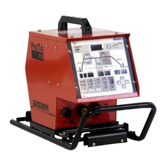
1.2. PRODUCT INTRODUCTION Protig 410 is a TIG ignition unit for demanding professional use. The unit is controlled by means of a microprocessor and ignition spark is generated by means of thyristors. These operation instructions are for Protig 410 ignition unit, assembly and installation of TIG equipment as well as panel functions. - Page 4 Remote control unit Pro Power source Control cable Shielding gas hose Snap connector - 0 Welding current cable 16d Extension cable for remote control Earth cable MMA welding cable 23b TIG torch air-cooled 4 – PROTIG 410 / 0537 © KEMPPI OY...
-
Page 5: Accessories And Cables
R3/8 - Snap connector Shielding gas hose Snap connector - 0 Welding current cable Extension cable for remote control Earth cable MMA welding cable TIG torch liquid-cooled TIG extension cable liquid-cooled © KEMPPI OY PROTIG 410 / 0537 – 5... - Page 6 Welding current cable 16d Extension cable for remote control 17d Start extension cable Earth cable MMA welding cable 22b Mig gun liquid-cooled 23b TIG torch liquid-cooled 23d TIG extension cable liquid-cooled 6 – PROTIG 410 / 0537 © KEMPPI OY...
-
Page 7: Operation Safety
TIG equipment Lifting of wagon together with bottle is forbidden due to safety reasons! 2.1.3. Mounting of Protig 410 unit onto the power source (figure page 4) Lock the Protig unit carefully as shown in fig. onto pro power source. Loose unit might cause a danger situation. -
Page 8: Mounting Of Protig 410 Control Panel
2.1.6. Connecting torch and extension cable Connection to the Protig 410 unit is shown on page 4 (air-cooled torch) and on page 5 (liquid- cooled torch). Tighten connector of torch carefully in order to avoid heating, contact disturbances and mechanical damage of connector as well as gas leakage to inside of connector. -
Page 9: Remote Control Units
The flow rate is set according to the welding power used in the job. A suitable flow rate is normally 8 - 10 l/min. If the gas flow is not suitable, the welded joint will be sporous. Contact your local Kemppi-dealer for choosing gas and equipment. 2.3.1. Installing gas bottle Always fasten gas bottle properly in vertical position in a special holder on the wall or on a carriage. -
Page 10: Main Switch I/O
Purpose of this operation is to make maintenance intervals of pump longer. Read in operation instructions for the Procool 10 / Procool 30 unit the trouble situations of the liquid circulation system and protection against torch etc. damage. 10 – PROTIG 410 / 0537 © KEMPPI OY... -
Page 11: Operation Of Panels
1 s, the ignition must be repeated. Scratch ignition is not recommended. Control of ignition spark Spark power may cause interference with eletronics equipment, which are not properly pro- tected. If there is interference, use contact ignition. © KEMPPI OY PROTIG 410 / 0537 – 11... -
Page 12: Selection Of Torch Switch Operation
With + and - keys, parameters (time or current) are adjusted to higher or lower values. Adjustable operation is selected with arrow keys: welding current, current down-slope time or post gas time. Adjustment speed is growing during adjustment. 12 – PROTIG 410 / 0537 © KEMPPI OY... -
Page 13: Parallel Control Unit For Welding Current
Intermittent up- and down-slope operations are produced by pressing the switch for a short time. © KEMPPI OY PROTIG 410 / 0537 – 13... -
Page 14: Controls For Mma Welding
Selection of operation mode of torch switch (S23) Operation of control unit (S27), (S28) Display for post gas time (P25) Local and remote control of welding current (H26) Welding current display (P23) Controls for MMA welding 14 – PROTIG 410 / 0537 © KEMPPI OY... -
Page 15: Control Ranges For Time And Per Cent
Use arrow keys when you go over to control different functions. You can go to available controls by selected welding mode. It is indicated by pilot lamp, in which stage of operation flow chart you are now and which parameters can be controlled by you. © KEMPPI OY PROTIG 410 / 0537 – 15... -
Page 16: Controls For Continuous Welding
2, 4, 8 and 16 ms, controls are working in the normal way. Welding of thin materials can be considered as one application because there directing arc to narrow range is very important, or if slow transportation speed is necessary. 16 – PROTIG 410 / 0537 © KEMPPI OY... -
Page 17: Controls For Fusion Spot Welding
Current down-slope can also be stopped to value of that moment by keeping the switch pressed down. When the switch is released, current down-slope is continued until the down-slope time is at end. © KEMPPI OY PROTIG 410 / 0537 – 17... -
Page 18: Program Storing Of Selectotig
ACCURACY OF PANEL DISPLAY Accuracy of digital meters in TL and TX panels as follows: Accuracy of current set value in ratio to true value is ±2,5 %, ±2 A. 18 – PROTIG 410 / 0537 © KEMPPI OY... -
Page 19: Remote Control Unit
Limiting of welding current range with min. and max. potentiometers (reference scale 1...10). MAINTENANCE The amount of use and the working environment should be taken into consideration when plan- ning the frequency of maintenance of Protig 410 unit. Careful use and preventive maintenance will help to ensure trouble-free operation. 6.1. -
Page 20: Cables
Torch or extension cable is wet. There are leakages due to moisture or dirt in connectors or cables of Protig 410 unit. At low current too big or blunt electrode. If with operation disturbances there comes to current display continuously error code in form ”E + number”, take contact with Kemppi service work shop and tell them also above-... -
Page 21: Ordering Numbers
Promig 511 6232511 Promig 530 6232530 Promig 501 + Protig Intermediate cable PROTIG/MIG 501-III-W 1m - 50 mm 3135780 Promig 511 + Protig Intermediate cable PROTIG/MIG 511-III-W 1m - 50 mm 3135790 © KEMPPI OY PROTIG 410 / 0537 – 21... -
Page 22: Technical Data
The product meets conformity requirements for CE marking. IP 34 means that the device is protected against water coming from any direction, directly or splashing. Control panels Main operations of Protig 410 panels TL and TX are in enclosed table. TL 6271265 TX 6271266 Spark ignition... -
Page 23: Terms Of Guarantee
Guarantee repairs must be carried out only by an Authorised Kemppi Service Agent. Packing, freight and insurance costs to be paid by orderer. The guarantee is effected on the date of purchase. Verbal promises which do not comply with the terms of guarantee are not binding on guarantor.
Need help?
Do you have a question about the Protig 410 and is the answer not in the manual?
Questions and answers