
Related Manuals for SICK CLX490


Summary of Contents for SICK CLX490
- Page 1 O P E R A T I N G I N S T R U C T I O N S CLX490 Compact OMNI Scanner for Bar Codes Omni Line...
- Page 2 Acrobat Reader is a trademark of the Adobe Systems Incorporated. Latest manual version For the latest version of this manual (PDF), see www.sick.com. © SICK AG · Division Auto Ident · Germany · All rights reserved 8009237/RB47/2007-08-03...
- Page 3 Chapter 6.4 Configuring (parameterization) the CLX, Page 6-4 • Troubleshooting – Chapter 8 Troubleshooting, Page 8-1 • Finding information – Table of contents, Page I -5 Index, Page 10 -49 – © SICK AG · Division Auto Ident · Germany · All rights reserved 8009237/RB47/2007-08-03...
- Page 4 17. Save the parameter set as a configuration file "*.scl" in the "CLV-Setup" program. The CLX can then be operated with the application-specific settings. © SICK AG · Division Auto Ident · Germany · All rights reserved 8009237/RB47/2007-08-03...
-
Page 5: Table Of Contents
Mounting the sensors for detecting the object distance........4-9 Dismantling the device ......................4-10 Electrical installation ....................5-1 Installation sequence ......................5-1 5.1.1 SICK Connection Modules (overview) ..............5-1 © SICK AG · Division Auto Ident · Germany · All rights reserved 8009237/RB47/2007-08-03... - Page 6 Switching off the CLX ......................6-26 Maintenance......................... 7-1 Maintenance during operation ....................7-1 Cleaning the CLX........................7-1 7.2.1 Cleaning the front window....................7-1 7.2.2 Cleaning other optical surfaces..................7-2 © SICK AG · Division Auto Ident · Germany · All rights reserved 8009237/RB47/2007-08-03...
- Page 7 10.6.1 Preparations........................10-15 10.6.2 Installing the software ....................10-15 10.6.3 Starting CLV-Setup ......................10-18 10.6.4 User interface ........................10-20 10.6.5 Functions .........................10-21 10.6.6 Hot keys...........................10-21 10.6.7 Opening and closing tabs..................10-22 © SICK AG · Division Auto Ident · Germany · All rights reserved 8009237/RB47/2007-08-03...
- Page 8 10.14.1 CLV Connect (from version 1.9) ................10-40 10.15 Glossary ..........................10-41 10.16 EC Declaration of Conformity..................10-47 10.17 Index............................10-49 10.18 Bar code example......................10-53 © SICK AG · Division Auto Ident · Germany · All rights reserved 8009237/RB47/2007-08-03...
- Page 9 Table 5-22: Pin and terminal assignment for "Result 1 to Result 4" switching outputs..........................5-20 Table 5-23: Characteristic data of the "Result 1 to Result 4" switching outputs... 5-20 © SICK AG · Division Auto Ident · Germany · All rights reserved 8009237/RB47/2007-08-03...
- Page 10 Table 10-14: Accessories: cables and connector covers for the CLX with heater ..10-38 Table 10-15: Accessories: plug-in connections ................10-38 Table 10-16: Supplementary documentation in English language ........10-40 © SICK AG · Division Auto Ident · Germany · All rights reserved I-10 8009237/RB47/2007-08-03...
- Page 11 Fig. 10-10: CLX with heater: Temperature curve inside the housing......... 10-12 Fig. 10-11: CLV-Setup: Result display of the AutoBaud Detect function......10-19 Fig. 10-12: User interface of the CLV-Setup software............. 10-20 © SICK AG · Division Auto Ident · Germany · All rights reserved I-11 8009237/RB47/2007-08-03...
- Page 12 Fig. 10-18: Reproduction of the declaration of conformity (Page 1, reduced in size)....................10-47 Fig. 10-19: Scannable bar codes with various module widths (print ratio 2:1) .....10-53 © SICK AG · Division Auto Ident · Germany · All rights reserved I-12 8009237/RB47/2007-08-03...
-
Page 13: Notes On This Document
Exchanging the device without losing the parameter set • Special applications and procedures The CLX490 Compact OMNI Scanner with all its variants will in this manual be referred to as the "CLX", except where a distinction is necessary. Target audience This document is intended for persons who are responsible for the following activities: 1.2.1... -
Page 14: Symbols
Operational instructions comprising several steps are denoted using consecutive numbers. Here you select a function of the "CLV-Setup" user interface. © SICK AG · Division Auto Ident · Germany · All rights reserved 8009237/RB47/2007-08-03... -
Page 15: Safety Information
Note Any warranty claims against SICK AG shall be deemed invalid in the case of other system use or system modifications, this includes modifications during installation and electrical in- stallation, changes to the SICK software, or opening the device. -
Page 16: General Safety Instructions And Protection Measures
As with sunlight, never look directly into the laser beam. Do not direct the laser beam at the eyes of other persons. Mount and align the CLX490 in such a way to prevent the laser beam reflecting off mirrored surfaces. -
Page 17: Fig. 2-1: Laser Warning Labels On The Clx
In Reading mode, the CLX carries out a measurement referencing at regular intervals. During referencing, it turns the laser diode on for a maximum of 10 seconds. © SICK AG · Division Auto Ident · Germany · All rights reserved 8009237/RB47/2007-08-03... -
Page 18: Quick Stop And Quick Restart
2 count, no match count) 2.4.2 Restarting the CLX Switch on the power supply or reattach the cables of the CLX490 to the connection module. The CLX resumes operation with the parameter set that was last stored permanently and reset the daily operating data. -
Page 19: Product Description
System requirements CLX without heater The following are required to start up and operate the CLX without heater: 1. A SICK Connection Module to provide the power supply and connect the data and func- tion interfaces. Available types: – For connecting one CLX: AMV60-011 (no. - Page 20 AMV200-011 (no. 6021106) for 18 to 30 V DC, enclosure rating max. IP 65 – or – Alternatively, a non-SICK Power pack with a voltage output of 18 to 30 V DC (functional extra-low voltage pursuant to IEC 364-4-41) and a minimum power output of 20 W.
-
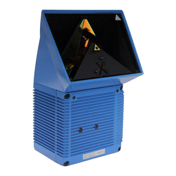
Page 21: Fig. 3-1: Design Of The Clx
6 mm deep reading angle ➒ LED (status indicators) ➏ Blind hole thread M4, 10 mm deep, for the connector cover Design of the Fig. 3-1: © SICK AG · Division Auto Ident · Germany · All rights reserved 8009237/RB47/2007-08-03... -
Page 22: Method Of Operation
CLV-Setup software or via the host interface/auxiliary interface using command strings. System, warning, and error messages help you configure the device and locate the source of errors during startup and reading mode. © SICK AG · Division Auto Ident · Germany · All rights reserved 8009237/RB47/2007-08-03... -
Page 23: Autofocus Function
3-3). Measured distance Optimum focus position: measured distance plus offset for maximum Depth of field (DOF) Fig. 3-3: Optimization the depth of field for the object © SICK AG · Division Auto Ident · Germany · All rights reserved 8009237/RB47/2007-08-03... -
Page 24: Event-Controlled Dynamic Focus Control
For information on applications and operating procedures, see Chapter 10.3 Installing and operating the external parameter memory, Page 10-8. © SICK AG · Division Auto Ident · Germany · All rights reserved 8009237/RB47/2007-08-03... -
Page 25: Indicators And Control Elements
Read Result Data Fig. 3-5: LEDs The meaning of the LEDs in the various operating modes/functions is shown in Table 3-2, Page 3-8 Table 3-3, Page 3-9. © SICK AG · Division Auto Ident · Germany · All rights reserved 8009237/RB47/2007-08-03... -
Page 26: Table 3-2: Meaning Of Leds: Clx Without External Parameter Memory
D tab in the "CLV-Setup" program. Download to CLX! TART WITH THE INTERNAL ARAMETERS EVICE ONFIGURATION Table 3-2: Meaning of LEDs: CLX without external parameter memory © SICK AG · Division Auto Ident · Germany · All rights reserved 8009237/RB47/2007-08-03... -
Page 27: Table 3-3: Meaning Of Leds: Clx With External Parameter Memory
Page 8-3 2) Stops blinking when you switch from Reading mode to Parameterization mode Table 3-3: Meaning of LEDs: CLX with external parameter memory © SICK AG · Division Auto Ident · Germany · All rights reserved 8009237/RB47/2007-08-03... - Page 28 • Blinks five times a second if reading rate 70 % to 90 % • Lights up constantly if reading rate > 90 % Table 3-3: Meaning of LEDs: CLX with external parameter memory (contd.) © SICK AG · Division Auto Ident · Germany · All rights reserved 3-10 8009237/RB47/2007-08-03...
-
Page 29: Installation
CLX) 4.2.3 Required auxiliary parts • 2 screws M6 for securing the SICK mounting bracket to the base. The screw length depends on the wall thickness of the base. • Set of laser warning labels (if necessary) •... -
Page 30: Replacing The Laser Warning Label
The CLX can be mounted at a maximum distance of 1,200 m from the host without a connection to the SICK network or a bus. In practice, however, the distance depends on the physical configuration of the host interface and the data transfer rate (see... -
Page 31: Mounting Accessories
Mounting possibilities of the CLX with angle bracket no. 2022996 The dimensions of the angle bracket is shown in Chapter 10.13 Dimensioned drawings of the accessories, Page 10-39. © SICK AG · Division Auto Ident · Germany · All rights reserved 8009237/RB47/2007-08-03... -
Page 32: Distance Between The Clx And The Object
Limit value Tilt α (azimuth) Omnidirectional Pitch β Max. 45° Skew γ Max. 45° Table 4-1: Permissible reading angles between the scan lines and bar code © SICK AG · Division Auto Ident · Germany · All rights reserved 8009237/RB47/2007-08-03... -
Page 33: Count Direction Of The Reading Angle Ra
OWNLOAD ARAMETERS 6. The CLX490 outputs the RA value on the host interface for each bar code in the reading result. The values are displayed as a 3-digit number in the associated "Code-Info/Sep- arator" block. -
Page 34: Mounting And Adjusting The Device
Chapter 5.5.3 Connecting the supply voltage, Page 5-13). After it has started, the CLX confirms that the self-test was successfuly and switches to reading mode ("Device Ready" LED lights up). © SICK AG · Division Auto Ident · Germany · All rights reserved 8009237/RB47/2007-08-03... - Page 35 (see Chapter 6.4.3 Guide to parameterization menu, Page 6-8). 15. Tighten the screws on the CLX. The CLX is aligned with the bar code. © SICK AG · Division Auto Ident · Germany · All rights reserved 8009237/RB47/2007-08-03...
-
Page 36: Mounting The External Components
8. Repeat the procedure with the conveyor switched on. Check whether the reading procedure is synchronized with the objects. © SICK AG · Division Auto Ident · Germany · All rights reserved 8009237/RB47/2007-08-03... -
Page 37: Mounting The Sensors For Detecting The Object Distance
5-18). It is advisable to mount these distance sensors opposite the direction of motion of the conveyor belt at approx. 100 mm in front of the reading pulse sensor. © SICK AG · Division Auto Ident · Germany · All rights reserved 8009237/RB47/2007-08-03... -
Page 38: Dismantling The Device
When removing the device from service for the last time, please dispose of it in an environmentally-friendly manner, as described in Chapter 7.4 Disposal, Page 7-3. © SICK AG · Division Auto Ident · Germany · All rights reserved 4-10 8009237/RB47/2007-08-03... -
Page 39: Electrical Installation
CLX490 Electrical installation Installation sequence • Connect the CLX to a SICK Connection Module from the series AMV/S, BMV/BMH10 or BMS20, or using a customer-specific wiring configuration • Connect the data and function interfaces of the CLX in the module •... -
Page 40: Electrical Connections And Cables
Table 5-2: Cables for connecting the CLX For technical data on the cables, see Chapter 10.12.5 Cables, external parameter memo- ries and plug cover, Page 10-37. © SICK AG · Division Auto Ident · Germany · All rights reserved 8009237/RB47/2007-08-03... -
Page 41: Connections/Cables For The Amv/S Connection Module
The module can be used to establish a connection to the host (point-to-point) or integrate the device in a SICK network or daisy-chain configuration (pass-through or master/slave configuration). The module is available in several variants... -
Page 42: Connections/Cables For The Bus Connection Modules Bmv10 And Bms20
2021689 • with two open cable ends, no. 2020981 • with one 9-pin D Sub cable connector and one open end, no. 2020308 © SICK AG · Division Auto Ident · Germany · All rights reserved 8009237/RB47/2007-08-03... -
Page 43: Connections/Cables For The Ip 65 Connector Cover (Connection To Amv100/200 Or Bmv10)
CLX, the temperature must not drop below max. –40 °C. Recommendation Use the external parameter memory no. 2020267 (open cable ends) for connecting the de- vice to non-SICK Power packs/wiring configurations. © SICK AG · Division Auto Ident · Germany · All rights reserved 8009237/RB47/2007-08-03... -
Page 44: Connector Pin Assignment
1) Pin 1 is jumpered with Pin 1 of the "Host/Term" connection in the CLX Table 5-4: Pin assignment of the 15-pin D Sub HD "I/O" socket © SICK AG · Division Auto Ident · Germany · All rights reserved 8009237/RB47/2007-08-03... -
Page 45: External Parameter Memory No. 2020307/2021689 (Optional Accessory) Connector Cover No. 2021298 (Optional Accessory)
1) Pin 1 is jumpered with Pin 1 of the "Host/Term" connection in the CLX 2) not connected Table 5-6: Pin assignment of the 15-pin D Sub HD "I/O" cable socket © SICK AG · Division Auto Ident · Germany · All rights reserved 8009237/RB47/2007-08-03... -
Page 46: Preparations For Electrical Installation
Power-up delay The selected device number (default: 1) affects the power-up delay of the device. This is useful if a large number of CLX (e. g. in the SICK network) are to be supplied from one power source. Table 5-9 contains a list of the available intervals. -
Page 47: Non-Sick Power Supply Unit/Connections Without The Connection Module
5.4.3 Non-SICK Power supply unit/connections without the Connection Module Power output If a non-SICK Power supply unit is used instead of the AMS60, it must be capable of providing the following voltage and power values: • for CLX without heater: 18 to 30 V DC, min. 20 W continuous power output •... -
Page 48: Table 5-11: Wire Color Assignment Of The Cable No. 2020264
2020981. Connect the free cable ends accordingly. The wire col- or assignments are shown in Table 5-12 Table 5-13. CLX with heater: Available on request. © SICK AG · Division Auto Ident · Germany · All rights reserved 5-10 8009237/RB47/2007-08-03... -
Page 49: Table 5-12: Wire Color Assignment Of Cable 1 For External Parameter Memory No. 2020981
Pin 1 is jumpered with Pin 1 of the "Host/Term" connection in the CLX Table 5-13: Wire color assignment of cable 2 for external parameter memory no. 2020981 © SICK AG · Division Auto Ident · Germany · All rights reserved 5-11... -
Page 50: Table 5-14: Wire Color Assignment Cable 1 For Connector Cover No. 2021267
TD– (RS 422/485), Host Grey-brown TxD (RS 232), Host – – Shield Orange Table 5-15: Wire color assignment cable 2 for connector cover no. 2021267 © SICK AG · Division Auto Ident · Germany · All rights reserved 5-12 8009237/RB47/2007-08-03... -
Page 51: Electrical Installation Procedur
5.5.3 Connecting the supply voltage a) SICK AMV/S and BMV10 Connection Modules If the CLX is powered via the SICK Connection Modules, the supply voltage does not have to be wired separately. Connecting the CLX without external parameter memory: 1. Make sure that the power supply to the Connection Module is switched off. -
Page 52: Connecting The Host Interface
RS 232 ( )=9-pin Sub D plug on PC RS 422 CAN-Network: Connection diagram for SICK CAN Scanner Network see "CLV Connect" program on CD-ROM Fig. 5-2: Connecting the host interface Risk of damage to the interface module! Electrical components in the CLX may be damaged if the host interface is connected incorrectly. -
Page 53: Connecting The Can Interface
ROTOCOL 5.5.5 Connecting the CAN interface For information on the connection and parameterization of the CLX for use in a SICK scanner network or in a CANopen network, see the Operating Instructions "Using the CAN interface" (no. 8009180, English version) 5.5.6... -
Page 54: Connecting The Switching Inputs
Chapter 5 Electrical installation Operating Instructions CLX490 Compact OMNI Scanner 3. Switch on the PC and power supply to the SICK Connection Module. 4. Set the communication parameters (see Chapter 10.6.3 Starting CLV-Setup, Page 10-18). In the default configuration, the auxiliary interface outputs the reading result in reading diagnosis mode. -
Page 55: Table 5-18: Pin And Terminal Assignment For "In 0 To In 4" Switching Inputs
Connect the sensors as shown in Fig. 5-5. For connecting the host interface via the AMV/S60 Connection Module, see the Operating Instructions for the "AMV/S60 Connection Module" (no. 8008296). © SICK AG · Division Auto Ident · Germany · All rights reserved 5-17 8009237/RB47/2007-08-03... -
Page 56: Table 5-19: Characteristic Data Of The "In 0 To N 4" Switching Inputs
1) 1 = energized (active); 0 = deenergized (inactive) 2) Distance configuration (DC): data record for focus position Table 5-20: Dynamic focus control: switching inputs/distance configuration assignment table © SICK AG · Division Auto Ident · Germany · All rights reserved 5-18 8009237/RB47/2007-08-03... -
Page 57: Connecting The "Result 1 To Result 2" Switching Outputs
24 V DC +20 %/–10 % for CLX with heater for Result X see Table 5-22 Fig. 5-6: Connections of the "Result 1 to Result 4" switching outputs © SICK AG · Division Auto Ident · Germany · All rights reserved 5-19 8009237/RB47/2007-08-03... -
Page 58: Table 5-22: Pin And Terminal Assignment For "Result 1 To Result 4" Switching Outputs
To check the switching functions using a high-impedance digital voltmeter, connect a load to the outputs to prevent incorrect voltage values/switching statuses from being displayed. © SICK AG · Division Auto Ident · Germany · All rights reserved 5-20 8009237/RB47/2007-08-03... -
Page 59: Operation
CLV-Setup prints out the complete set of default settings in the form of a table. The header contains the company and user names that were entered during the CLV-Setup installation routine. © SICK AG · Division Auto Ident · Germany · All rights reserved 8009237/RB47/2007-08-03... -
Page 60: Default Settings Of The Clx490
RS 232, 9,600 bd, 8 data bits, no parity, 1 stop bit (values cannot be changed) Function Reading diagnosis Table 6-1: Extract CLX490: Default parameter settings © SICK AG · Division Auto Ident · Germany · All rights reserved 8009237/RB47/2007-08-03... -
Page 61: Quick Start
Fig. 6-1: Bar code pattern (Code 39; module width 0.35 mm; Print ratio 2:1) © SICK AG · Division Auto Ident · Germany · All rights reserved 8009237/RB47/2007-08-03... -
Page 62: Configuring (Parameterization) The Clx
CLX, this first has to be loaded to CLV-Setup from the CLX. This procedure is referred to as an upload ("Upload from CLV" in the CLX490 menu or [F3] key) during which CLV-Setup always loads a complete copy of the current CLX parameter set. - Page 63 2. Enter the file name in the dialog box (file name extension "*.scl") and confirm the entry. The new parameter set is now stored in CLV-Setup in the subdirectory "data". © SICK AG · Division Auto Ident · Germany · All rights reserved 8009237/RB47/2007-08-03...
-
Page 64: Function Of The Tabs In Clv-Setup (Overview)
Special parameters of the SMART decoder (e. g. for OTS mode) Recommendation To enhance the reading reliability with fast applications, only activate those code types and code lengths that are actually relevant. © SICK AG · Division Auto Ident · Germany · All rights reserved 8009237/RB47/2007-08-03... - Page 65 CLV-Setup Online Help contains a detailed description of the functions of the parameters and their valid entries (see Chapter 10.6.8 CLV-Setup Help, Page 10-22 for calling up Help). © SICK AG · Division Auto Ident · Germany · All rights reserved 8009237/RB47/2007-08-03...
-
Page 66: Guide To Parameterization Menu
Blank zone Start/stop ratio EADING CONFIGURATION • Poor quality bar code print Code label characteristics EADING CONFIGURATION • Relative module width Code label characteristics EADING CONFIGURATION © SICK AG · Division Auto Ident · Germany · All rights reserved 8009237/RB47/2007-08-03... -
Page 67: Table 6-3: Guide: Parameterizing The Autofocus Mode (Part 1)
5. Tracking parameter: – – focus release point ❍ ❍ 6. Teach-in background – ✖ : required ❍: optional Table 6-4: Guide: Parameterizing the autofocus function (Part 2) © SICK AG · Division Auto Ident · Germany · All rights reserved 8009237/RB47/2007-08-03... -
Page 68: Table 6-5: Guide: Parameterizing The Event-Controlled Focus Control
ERIAL EVICE ONFIGURATION mode: choose function for IN 4 SSIGNMENT "IN 4" switching input – Focus Control Table 6-5: Guide: Parameterizing the event-controlled focus control © SICK AG · Division Auto Ident · Germany · All rights reserved 6-10 8009237/RB47/2007-08-03... -
Page 69: Table 6-6: Guide: Parameterizing The Reading Trigger Source
Codes and Edit Codes ONFIGURATION • Activate code comparison Match Codes Parameters EVICE ONFIGURATION • Define output time of reading result Output on Good Read ONFIGURATION © SICK AG · Division Auto Ident · Germany · All rights reserved 6-11 8009237/RB47/2007-08-03... -
Page 70: Table 6-8: Guide: Parameterizing The Separation Of Identical Bar Codes
Arrangement in data network section EVICE ONFIGURATION CANNER ARRANGEMENT • Physical interface section OST INTERFACE ORMAT • Communication parameters section NTERFACE ORMAT • Protocol section NTERFACE NTERFACE ROTOCOL © SICK AG · Division Auto Ident · Germany · All rights reserved 6-12 8009237/RB47/2007-08-03... - Page 71 Parameterizing the auxiliary interface (auxiliary interface) • UXILIARY NTERFACE f) Defining the start option for accessing the parameter set • On the D choose S EVICE ONFIGURATION TART WITH © SICK AG · Division Auto Ident · Germany · All rights reserved 6-13 8009237/RB47/2007-08-03...
-
Page 72: Operating Modes And Outputing The Reading Result
The "Sensor" LED lights up and the red scan line appears. Also refer to Chapter 6.3.1 Switching the CLX on for the first time with the factory default settings, Page 6-3. © SICK AG · Division Auto Ident · Germany · All rights reserved 6-14 8009237/RB47/2007-08-03... -
Page 73: Fig. 6-2: Clv-Setup: Displaying The Reading Result Of The Auxiliary Interface In The Terminal Emulator
Fig. 6-2: CLV-Setup: Displaying the reading result of the auxiliary interface in the Terminal Emulator © SICK AG · Division Auto Ident · Germany · All rights reserved 6-15 8009237/RB47/2007-08-03... -
Page 74: Fig. 6-3: Reading Result Of The Auxiliary Interface: Structure For "Good Read
2nd. line: no code! = No bar codes found! 1) not relevant for autofocus function Fig. 6-4: Reading result of the auxiliary interface: structure for "No Read" © SICK AG · Division Auto Ident · Germany · All rights reserved 6-16 8009237/RB47/2007-08-03... -
Page 75: Percentage Evaluation
The standard decoder has to be set temporarily for the percentage evaluation. 1. Choose the C tab. ONFIGURATION 2. In the D section, choose S ECODER TANDARD © SICK AG · Division Auto Ident · Germany · All rights reserved 6-17 8009237/RB47/2007-08-03... -
Page 76: Fig. 6-5: Clv-Setup: Displaying The Percentage Evaluation In The Terminal Emulator
The LED blinks five times per second if the reading quality is 70 % to 90 % – The LED is lit continuously if the reading quality is > 90 % © SICK AG · Division Auto Ident · Germany · All rights reserved 6-18 8009237/RB47/2007-08-03... -
Page 77: Background Teach-In
If the parameters in the CLX were modified as a result of the teach-in procedure, CLV- Setup asks you whether you want to copy and display the modified parameter set by uploading it from the CLX. © SICK AG · Division Auto Ident · Germany · All rights reserved 6-19 8009237/RB47/2007-08-03... -
Page 78: Fig. 6-7: Clv-Setup: Display Of The Learned Background
2 angular elements. If no background has been taught in, the CLX uses the default background (2,200 mm across the entire distance profile). © SICK AG · Division Auto Ident · Germany · All rights reserved 6-20 8009237/RB47/2007-08-03... -
Page 79: Displaying And Editing Operating Data
2. Perform a download to the CLX by clicking in the toolbar. The D dialog box is then displayed. OWNLOAD ARAMETERS 3. Choose the P storage option in the dialog box. ERMANENT © SICK AG · Division Auto Ident · Germany · All rights reserved 6-21 8009237/RB47/2007-08-03... -
Page 80: Monitor Host Interface
Fig. 6-1, Page 6-3. 5. Click the SW-T button or press [F8]. RIGGER CLV-Setup outputs the reading result in the Terminal Emulator. Example: "O 0123412345". © SICK AG · Division Auto Ident · Germany · All rights reserved 6-22 8009237/RB47/2007-08-03... -
Page 81: Fig. 6-9: Clv-Setup: Displaying The Reading Result Of The Host Interface In The Terminal Emulator With Direction Identifier At The Beginning (In This Case: O = Output)
4. Confirm the entries made by clicking OK. 5. Repeat this procedure for the "Code-Info/Separator", "Splitter" und "Terminator" blocks. © SICK AG · Division Auto Ident · Germany · All rights reserved 6-23 8009237/RB47/2007-08-03... -
Page 82: Auxiliary Input
The CLX then returns to the Reading mode and the "Device Ready" LED lights up. Fig. 6-10: CLV-Setup: Displaying the self-test result in the terminal emulator © SICK AG · Division Auto Ident · Germany · All rights reserved 6-24 8009237/RB47/2007-08-03... -
Page 83: Executing Clx Functions Interactively
Chapter 10.5 System messages, Page 10-14 explains the contents of the messages. Error messages: Error messages indicate the following types of error: • a device defect © SICK AG · Division Auto Ident · Germany · All rights reserved 6-25 8009237/RB47/2007-08-03... -
Page 84: Switching Off The Clx
3. Make the necessary entries in the dialog box and confirm these. CLV-Setup prints out the current configuration file in the form of a table. © SICK AG · Division Auto Ident · Germany · All rights reserved 6-26 8009237/RB47/2007-08-03... -
Page 85: Maintenance
Note Electrostatic charges cause dust particles to stick to the reading window. This effect can be combated by using anti-static SICK synthetic cleaner (no. 5600006) in combination with a SICK lens cloth (no. 4003353). Use a clean, soft brush to free the reading window (Fig. -
Page 86: Cleaning Other Optical Surfaces
In order to prevent incorrect switching behaviour, remove soiling from the optical effec- tive surfaces of the external sensors. Clean here Fig. 7-2: Cleaning the external optical sensors (reading pulse generator, object-height detector) © SICK AG · Division Auto Ident · Germany · All rights reserved 8009237/RB47/2007-08-03... -
Page 87: Checking The Incremental Encoder
4. Send the chassis and cover (aluminium) to be recycled. 5. Send the electronic modules for disposal as problem waste. At present, SICK AG does not accept any unusable or irreparable devices. © SICK AG · Division Auto Ident · Germany · All rights reserved 8009237/RB47/2007-08-03... - Page 88 Chapter 7 Maintenance Operating Instructions CLX490 Compact OMNI Scanner Notes: © SICK AG · Division Auto Ident · Germany · All rights reserved 8009237/RB47/2007-08-03...
-
Page 89: Troubleshooting
CLX outputs the message: "Laser safety timeout" on the auxiliary interface. The reading interval must be terminated by resetting the trigger signal. The laser diode is activated again by the next reading trigger. © SICK AG · Division Auto Ident · Germany · All rights reserved 8009237/RB47/2007-08-03... -
Page 90: Error Messages
Download the parameter set to Background profile the CLX! invalid Center reading angle RA 50 implausible Brightness overflow 201to215DSP error Table 8-1: Error messages output on the auxiliary interface © SICK AG · Division Auto Ident · Germany · All rights reserved 8009237/RB47/2007-08-03... -
Page 91: Led Error Messages For The External Parameter Memory
2) Flashing stops when the device switches from Reading mode to Parameter mode (e. g. during download from CLV-Setup). Table 8-2: LED error messages for access to the external parameter memory © SICK AG · Division Auto Ident · Germany · All rights reserved 8009237/RB47/2007-08-03... - Page 92 CLX briefly and monitor the "Device Ready" LED as described under 1. Table 8-2: LED error messages for access to the external parameter memory (contd.) © SICK AG · Division Auto Ident · Germany · All rights reserved 8009237/RB47/2007-08-03...
-
Page 93: Messages For Errors Accessing The External Parameter Memory
RAM the SICK Service department. Table 8-3: For messages for problems accessing the external parameter memory © SICK AG · Division Auto Ident · Germany · All rights reserved 8009237/RB47/2007-08-03... - Page 94 If these parameters are necessary, edit the values in the relevant tabs in CLV-Setup and download them to the CLX and the external memory. Table 8-3: For messages for problems accessing the external parameter memory (contd.) © SICK AG · Division Auto Ident · Germany · All rights reserved 8009237/RB47/2007-08-03...
-
Page 95: St Error Status In The Reading Result Of A Bar Code
6-digit C39 bar codes as error string instead. C32 bar codes (output as 9-digit deci- mal values). Table 8-4: Meaning of the ST error status in the reading result © SICK AG · Division Auto Ident · Germany · All rights reserved 8009237/RB47/2007-08-03... - Page 96 N UMBER OF ODES INIMUM Table 8-4: Meaning of the ST error status in the reading result © SICK AG · Division Auto Ident · Germany · All rights reserved 8009237/RB47/2007-08-03...
-
Page 97: General Malfunctions: Clx Not Ready
Chapter 6.4.3 Guide to parameteri- the current reading pulse (Trigger mode: zation menu, Page 6-8, Section Adjust sensor input/serial interface) Laser timeout Table 8-5: Troubleshooting: restoring operation (Reading mode) © SICK AG · Division Auto Ident · Germany · All rights reserved 8009237/RB47/2007-08-03... -
Page 98: Malfunctions In Reading Mode: Reading Trigger Errors
EADING RIGGER ARAMETERS section: is Genera- ND OF EADING NTERVAL ted by Trigger Source selected? Table 8-6: Troubleshooting: reading trigger errors in Reading mode © SICK AG · Division Auto Ident · Germany · All rights reserved 8-10 8009237/RB47/2007-08-03... -
Page 99: Malfunctions In Reading Mode: Result Output Errors
(reading quality > 70 %!). If necessary, realign CLX and/or reconfigure distance configuration. If ok, choose SMART DECO . Download to CLX. Table 8-7: Troubleshooting: result output errors in Reading mode © SICK AG · Division Auto Ident · Germany · All rights reserved 8-11 8009237/RB47/2007-08-03... - Page 100 Is the T check- RANSMIT HECK IGIT box activated? Change if necessary. Download to CLX! Table 8-7: Troubleshooting: result output errors in Reading mode (contd.) © SICK AG · Division Auto Ident · Germany · All rights reserved 8-12 8009237/RB47/2007-08-03...
-
Page 101: Malfunctions In Reading Mode: Errors In The Result Status Output
Download to CLX! (default setting: Match 1) switching outputs are not outputting any pulses Table 8-8: Troubleshooting: errors in the result status output in Reading mode © SICK AG · Division Auto Ident · Germany · All rights reserved 8-13 8009237/RB47/2007-08-03... -
Page 102: Sick Support
Chapter 10.11 Repla- cing a CLX (copying the parameter set), Page 10-33. Please contact our local SICK office or subsidary if an error occurs which cannot be eli- minated: • The telephone numbers and email addresses are listed on the back page of this manual. -
Page 103: Technical Data
1) Default setting, in Reading mode with the Switching input sensor and Serial interface pulse types. 2) Reading interval: time window generated internally for evaluating the code. Table 9-1: Technical specifications of the CLX490-0010 © SICK AG · Division Auto Ident · Germany · All rights reserved 8009237/RB47/2007-08-03... -
Page 104: Data Sheet Clx490-0011 Compact Omni Scanner
175.5 Drilled hole, M6, 7 mm deep Blind hole thread, ∅ 3.6 mm, 6 mm deep All dimensions in mm Fig. 9-1: Dimensions of the CLX © SICK AG · Division Auto Ident · Germany · All rights reserved 8009237/RB47/2007-08-03... -
Page 105: Appendix
Good Read rate > 75 % Table 10-1: Reading conditions for specification diagrams Note The min. and max. reading distances are measured radially by the CLX. © SICK AG · Division Auto Ident · Germany · All rights reserved 10-1 8009237/RB47/2007-08-03... -
Page 106: Reading Performance Data Clx490 Compact Omni Scanner
Chapter 10 Appendix Operating Instructions CLX490 Compact OMNI Scanner 10.2.2 Reading performance data CLX490 Compact OMNI Scanner Fig. 10-1: Diagram: Reading field (reading limits) © SICK AG · Division Auto Ident · Germany · All rights reserved 10-2 8009237/RB47/2007-08-03... - Page 107 Reading distance (mm) Resolution: 0.35 mm Reading conditions: 0.50 mm Table 10-1, Page 10-1 Fig. 10-2: Scanning frequency as a function of the reading distance and resolution © SICK AG · Division Auto Ident · Germany · All rights reserved 10-3 8009237/RB47/2007-08-03...
-
Page 108: Reading Field And System Dimensions
Reading field and system dimensions Fig. 10-3: Required mounting position of the CLX above the conveyor belt (resolution 0.30 mm, conveyor belt width 300 mm) © SICK AG · Division Auto Ident · Germany · All rights reserved 10-4 8009237/RB47/2007-08-03... -
Page 109: Fig. 10-4: Required Mounting Position Of The Clx Above The Conveyor Belt (Resolution 0.35 Mm, Conveyor Belt Width 400 Mm)
Operating Instructions Appendix Chapter 10 CLX490 Fig. 10-4: Required mounting position of the CLX above the conveyor belt (resolution 0.35 mm, conveyor belt width 400 mm) © SICK AG · Division Auto Ident · Germany · All rights reserved 10-5 8009237/RB47/2007-08-03... -
Page 110: Fig. 10-5: Required Mounting Position Of The Clx Above The Conveyor Belt (Resolution 0.50 Mm, Conveyer Belt Width 400 Mm)
Operating Instructions CLX490 Compact OMNI Scanner Fig. 10-5: Required mounting position of the CLX above the conveyor belt (resolution 0.50 mm, conveyer belt width 400 mm) © SICK AG · Division Auto Ident · Germany · All rights reserved 10-6 8009237/RB47/2007-08-03... -
Page 111: Fig. 10-6: Depth Of Field As A Function Of Module Width And Focus Position At A Belt Width Of 400 Mm
1500 1600 1700 1800 Fig. 10-6: Depth of field as a function of module width and focus position at a belt width of 400 mm © SICK AG · Division Auto Ident · Germany · All rights reserved 10-7 8009237/RB47/2007-08-03... -
Page 112: Installing And Operating The External Parameter Memory
The "Device Ready" and "Read Result" LEDs indicate whether the external memory was accessed successfully. The CLX also outputs plain-text messages for trouble- shooting purposes on the auxiliary interface. © SICK AG · Division Auto Ident · Germany · All rights reserved 10-8 8009237/RB47/2007-08-03... -
Page 113: Installation And Electrical Connection
The "Device Ready" LED blinks for approx. 10 s and then lights up constantly. The data in the CLX is lost when the device is switched off. © SICK AG · Division Auto Ident · Germany · All rights reserved 10-9... -
Page 114: Switching On The Device For The First Time
CLV-Setup: dialog box for adjusting the external parameter memory Adjust the parameter set in the external parameter memory as described in Chapter 6.4.1 Configuring the CLX with CLV-Setup, Page 6-4. © SICK AG · Division Auto Ident · Germany · All rights reserved 10-10 8009237/RB47/2007-08-03... -
Page 115: Meaning Of The Leds
(default). This is the case when the device is put into service for the first time, e. g. when it is taken from the warehouse. The device must be replaced with a device of the same type (e. g. CLX490-0010 with CLX490-0010). You do not need to connect a PC to replace the device. -
Page 116: Optional Heating
(°C) The temperature enables the operating voltage for the CLX internally Time (min) Fig. 10-10: CLX with heater: Temperature curve inside the housing © SICK AG · Division Auto Ident · Germany · All rights reserved 10-12 8009237/RB47/2007-08-03... -
Page 117: Electrical Installation
If the CLX with integrated heater is used outdoors, it should be installed in a protective hous- ing to prevent the front window from being damaged by rain, snow, or dust. The housing also acts as a wind protector. © SICK AG · Division Auto Ident · Germany · All rights reserved 10-13 8009237/RB47/2007-08-03... -
Page 118: System Messages
When the CLX was started, the internal parameter set was external memory" successfully copied to the external parameter memory. Table 10-4: Additional CLX system messages for the connected parameter memory © SICK AG · Division Auto Ident · Germany · All rights reserved 10-14 8009237/RB47/2007-08-03... -
Page 119: Installing And Operating The "Clv-Setup" Program
CD-ROM. ILE DOWNLOAD Confirm with OK. The software is automatically saved in the “Programs\CLV“ directory on your hard disk. – or – © SICK AG · Division Auto Ident · Germany · All rights reserved 10-15 8009237/RB47/2007-08-03... - Page 120 If you want to install the new version and still keep the old version of CLV-Setup, follow the procedure described under Initial installation. When the program asks you for the target © SICK AG · Division Auto Ident · Germany · All rights reserved 10-16...
- Page 121 3. Install the new version of CLV-Setup as described under Initial installation, making sure to choose the same directory. The new version of CLV-Setup is installed. The configuration files of the old version can be used again. © SICK AG · Division Auto Ident · Germany · All rights reserved 10-17 8009237/RB47/2007-08-03...
-
Page 122: Starting Clv-Setup
The default setting the first time the device is used is the CLV41x. The software then loads the internal device description for this CLV type and displays the default values on the tabs. © SICK AG · Division Auto Ident · Germany · All rights reserved 10-18 8009237/RB47/2007-08-03... -
Page 123: Fig. 10-11: Clv-Setup: Result Display Of The Autobaud Detect Function
CLV-Setup then uploads the current parameter set from the RAM of the CLX to its database and displays the values on the tabs. You can edit the current parameter set on the tabs. © SICK AG · Division Auto Ident · Germany · All rights reserved 10-19 8009237/RB47/2007-08-03... -
Page 124: User Interface
CLX, the PC’s interface parameter display, error display field (system errors), device specification field and status display for the connection to the CLX. Fig. 10-12: User interface of the CLV-Setup software © SICK AG · Division Auto Ident · Germany · All rights reserved 10-20 8009237/RB47/2007-08-03... -
Page 125: Functions
Save configuration file [F7] Load default setting of CLX from CLV-Setup database [F8] Start AutoBaud Detect [F9] Load operating data from CLX to be displayed and reset © SICK AG · Division Auto Ident · Germany · All rights reserved 10-21 8009237/RB47/2007-08-03... -
Page 126: Opening And Closing Tabs
5. In the left-hand frame click on the desired entry in the navigation tree. CLV-Setup Help then displays the associated help text in the right-hand frame and jumps to the parameter heading. © SICK AG · Division Auto Ident · Germany · All rights reserved 10-22 8009237/RB47/2007-08-03... -
Page 127: Transferring Parameter Sets Between Clv-Setup And The Clx
If the program detects an error, it outputs a warning and enters the problem parameter/ value in the window on the E tab. XTRAS © SICK AG · Division Auto Ident · Germany · All rights reserved 10-23 8009237/RB47/2007-08-03... -
Page 128: 10.6.11 Log File In The Terminal Emulator
In this way, for example, you can prevent CLV-Setup from attempting to establish a connection when a CLX is not connected. 10.6.13 The CLV Assistant The CLV Assistant is not suitable for parameterizing the CLX. © SICK AG · Division Auto Ident · Germany · All rights reserved 10-24 8009237/RB47/2007-08-03... -
Page 129: Configuring A Clx With Command Strings
The CLX answers with an echo if the command was syntactically correct (in most cases). Example: The command "3?LT" causes the CLX to display the parameter values of the reading trigger in coded form in output window © SICK AG · Division Auto Ident · Germany · All rights reserved 10-25 8009237/RB47/2007-08-03... - Page 130 If the commands are sent from the host/PLC to the CLX for configuration, note that "3 EEW" has to be sent as the last command to ensure that they are permanently transferred to the CLX (EEPROM). © SICK AG · Division Auto Ident · Germany · All rights reserved 10-26 8009237/RB47/2007-08-03...
-
Page 131: Calculating Parameter Values For Setting The Clx
PTIMIZE FOR SHORT CODE DISTANCES smaller code distances as described above are possible (depending on application) ARAMETER Fig. 10-14: Required distance between the bar codes on an object © SICK AG · Division Auto Ident · Germany · All rights reserved 10-27 8009237/RB47/2007-08-03... -
Page 132: Tables
Table 10-6: Formulas for calculating the code length of a bar code © SICK AG · Division Auto Ident · Germany · All rights reserved 10-28... -
Page 133: 10.10 Special Applications And Procedures
NPUT in the context menu. OWNLOAD ARAMETER CLV-Setup copies the parameter to the CLV temporarily. The auxiliary interface then operates temporarily in "Auxiliary input" mode. © SICK AG · Division Auto Ident · Germany · All rights reserved 10-29 8009237/RB47/2007-08-03... -
Page 134: Fig. 10-16: Clv-Setup: Auxiliary Input On The Terminal Emulator
6. Once the active reading pulse has ended, the CLX sends the data received from the PC to the host via the host interface. Fig. 10-16: CLV-Setup: auxiliary input on the Terminal Emulator © SICK AG · Division Auto Ident · Germany · All rights reserved 10-30 8009237/RB47/2007-08-03... -
Page 135: Table 10-7: Communication Parameters On The Terminal/Pc For The Auxiliary Input
Once the active reading pulse has ended, the CLX sends the data received from the PC to the host via the host interface. If you connect a SICK Hand-held Scanner from the IT 38xx/46xx/48xx/58xx series, set the communication parameters and data output (data + terminator) as shown in Table 10-8. -
Page 136: 10.10.2 Connection To The Profibus Dp
See Operating Instructions "Using the CAN interface" (Order no. 8009180, English edition). 10.10.7 Integration in an OPS reading system See Operating Instructions "Omni Tracking System OTS400" (Order no. 8008869, English edition). © SICK AG · Division Auto Ident · Germany · All rights reserved 10-32 8009237/RB47/2007-08-03... -
Page 137: Replacing A Clx (Copying The Parameter Set)
The new device, however, outputs an error message in CLV-Setup for each of these parame- ters/values when the parameter set is downloaded. © SICK AG · Division Auto Ident · Germany · All rights reserved 10-33 8009237/RB47/2007-08-03... -
Page 138: 10.11.2 Importing The Parameter Set From The External Memory
© SICK AG · Division Auto Ident · Germany · All rights reserved 10-34... -
Page 139: 10.12 Ordering Information
1017391 AMV30-071 Connection Module for two CLX490 without heater, with 2 x 15-pin D Sub HD device socket/plug, ter- minal strips (signal distributor) for connecting the data and function interfaces, two 9-pin D Sub "Service" plugs, strain-relief clamps, polycarbonate housing, enclosure rating IP 30 (max. -
Page 140: 10.12.4 Accessories: Bus Connection Modules
6020896 BMV10-0111 Bus Connection Module for connecting a CLX490 to a Profibus DP, for the CLX490 with 1 x 15-pin D Sub HD device socket/plug, bus connector, terminal strips (signal distributor) for connecting the RS 232 and function interfaces, internal 9-pin D Sub "Service" plug, strain-relief clamps, cast alumi- num housing, enclosure rating max. -
Page 141: 10.12.5 Cables, External Parameter Memories And Plug Cover
(RS 485) Table 10-13: Accessories: cables and connector covers for the CLX without heater Note Other cable lengths/types for CLX without heater available on request. © SICK AG · Division Auto Ident · Germany · All rights reserved 10-37 8009237/RB47/2007-08-03... -
Page 142: 10.12.6 Plug-In Connections
The SICK catalog "SENSICK Sensors for Automation" (order no. 8006530, English edition) contains a large selection of photoelectric switches and photoelectric proximity switches as well as the associated accessories (brackets, connection cables). © SICK AG · Division Auto Ident · Germany · All rights reserved 10-38 8009237/RB47/2007-08-03... -
Page 143: 10.13 Dimensioned Drawings Of The Accessories
2 x cylinder head screws M6 x 10 mm, self-locking Drill holes for fixation of CLX Fig. 10-17: Dimensions of the angle bracket, single No. 2022996 © SICK AG · Division Auto Ident · Germany · All rights reserved 10-39 8009237/RB47/2007-08-03... -
Page 144: 10.14 Supplementary Documentation
“CLV Connect“ PC program. This software is available on the “Manuals & Software“ CD-ROM, which is included in the scope of delivery of the CLX. The software can also be downloaded from the SICK home page (www.sick.com) at “Service&Support/Downloadpool“. -
Page 145: 10.15 Glossary
Can be assigned various functions. CAN interface Can be used for building a quick SICK specific CAN Scanner Network with several functions (e.g. multiplex function, master/slave configuration) or for the integration into an existing CAN network according to the CANopen protocol. - Page 146 (D ). You can overwrite the OWNLOAD ARAMETERS OF THIS VIEW existing parameter set in EEPROM of the CLX by choosing the "Permanent" save option. © SICK AG · Division Auto Ident · Germany · All rights reserved 10-42 8009237/RB47/2007-08-03...
- Page 147 Special arrangement for connecting up to max. 10 CLX to one reading station (e. g. left/right read) using the CAN interface. Thanks to the master, the entire network appears as one de- vice to the host. © SICK AG · Division Auto Ident · Germany · All rights reserved 10-43 8009237/RB47/2007-08-03...
- Page 148 Only output on the host interface if enabled on the D TRING in the "CLV-Setup" program (for the CLX disabled by default). © SICK AG · Division Auto Ident · Germany · All rights reserved 10-44 8009237/RB47/2007-08-03...
- Page 149 Contains up to 5 elements, consisting of constants (control characters, letters, digits), depending on the configuration. The "Splitter" block is empty in the default setting of the CLX. © SICK AG · Division Auto Ident · Germany · All rights reserved 10-45 8009237/RB47/2007-08-03...
- Page 150 ). Displays the current parameter values on the PLOAD ARAMETERS OF THIS tabs. Prerequisite for modifying the current parameter set. User interface Windows-based PC software "CLV-Setup" for operating and configuring the CLX. © SICK AG · Division Auto Ident · Germany · All rights reserved 10-46 8009237/RB47/2007-08-03...
-
Page 151: 10.16 Ec Declaration Of Conformity
The complete EC Declaration of Conformity with the listing of the device versions and the fullfilled standards can be requested from SICK AG. Fig. 10-18: Reproduction of the declaration of conformity (Page 1, reduced in size) © SICK AG · Division Auto Ident · Germany · All rights reserved 10-47 8009237/RB47/2007-08-03... - Page 152 Chapter 10 Appendix Operating Instructions CLX490 Compact OMNI Scanner Notes: © SICK AG · Division Auto Ident · Germany · All rights reserved 10-48 8009237/RB47/2007-08-03...
-
Page 153: 10.17 Index
CD ROM ....................3-1 Distance configuration Cleaning the CLX ................7-1 - Function..................3-6 CLV-Setup - Parameterization ..............6-10 - Default settings..............10-18 Distance profile - Download ..................6-5 © SICK AG · Division Auto Ident · Germany · All rights reserved 10-49 8009237/RB47/2007-08-03... - Page 154 - Electrical connection ............10-9 - Assignment table ..............5-18 - Error messages...............8-5 - Caracteristic data..............5-18 - Function ..................10-8 - Connection ................5-17 - LEDs ....................3-9 © SICK AG · Division Auto Ident · Germany · All rights reserved 10-50 8009237/RB47/2007-08-03...
- Page 155 - Mounting..................4-8 - Display in the Terminal Emulator ........6-25 - Parametrization for trigger source ........4-9 - Function..................3-4 Reading result - List of messages.............. 10-14 © SICK AG · Division Auto Ident · Germany · All rights reserved 10-51 8009237/RB47/2007-08-03...
- Page 156 Warning messages - Display in the Terminal Emulator ........6-25 - Function..................3-4 Working method of CLX - Block diagram ................. 3-4 - Description ................3-4 © SICK AG · Division Auto Ident · Germany · All rights reserved 10-52 8009237/RB47/2007-08-03...
-
Page 157: 10.18 Bar Code Example
2/5 Interleaved Module width Module width Module width 0.35 mm 0.5 mm 1.0 mm Fig. 10-19: Scannable bar codes with various module widths (print ratio 2:1) © SICK AG · Division Auto Ident · Germany · All rights reserved 10-53 8009237/RB47/2007-08-03... - Page 158 Brasil România Ceská Republika E-Mail sick@sick.cz Russia China E-Mail denis.kesaev@sick- Danmark Schweiz E-Mail sick@sick.dk Deutschland Singapore España Suomi France Sverige Great Britain Taiwan India Türkiye Italia USA/Canada/México Japan Nederlands Norge Österreich www.sick.com SICK AG | Waldkirch | Germany | www.sick.com...
Need help?
Do you have a question about the CLX490 and is the answer not in the manual?
Questions and answers