Sign In
Upload
Manuals
Brands
SICK Manuals
Scanner
Omni CLX490 Series
SICK Omni CLX490 Series Barcode Scanner Manuals
Manuals and User Guides for SICK Omni CLX490 Series Barcode Scanner. We have
2
SICK Omni CLX490 Series Barcode Scanner manuals available for free PDF download: Operating Instructions Manual
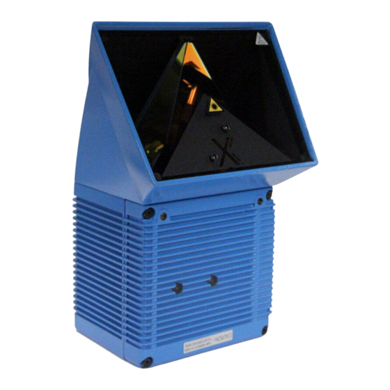
SICK Omni CLX490 Series Operating Instructions Manual (158 pages)
Compact OMNI Scanner for Bar Codes
Brand:
SICK
| Category:
Scanner
| Size: 2 MB
Table of Contents
Table of Contents
5
1 Notes on this Document
13
Purpose
13
Target Audience
13
Mounting, Electrical Installation, Maintenance and Replacement
13
Startup, Operation and Configuration
13
Information Content
13
Symbols
14
2 Safety Information
15
Authorized Users
15
Mounting and Maintenance
15
Electrical Installation and Replacement
15
Startup, Operation and Configuration
15
Intended Use
15
General Safety Instructions and Protection Measures
16
Fig. 2-1: Laser Warning Labels on the CLX
17
Quick Stop and Quick Restart
18
Stopping the CLX
18
Restarting the CLX
18
Environmental Information
18
Power Requirements
18
Disposal after Removal from Service
18
3 Product Description
19
Design
19
Scope of Delivery
19
Variants
19
System Requirements
19
Tab. 3-1: CLX Variants
19
Fig. 3-1: Design of the CLX
21
Method of Operation
22
Fig. 3-2: Block Diagram: CLX Functions
22
Autofocus Function
23
Fig. 3-3: Optimization the Depth of Field for the Object
23
Event-Controlled Dynamic Focus Control
24
Additional Components
24
Fig. 3-4: Dynamic Focus Control: Classification of the Reading Range in Distance Configurations
24
Indicators and Control Elements
25
Control Elements
25
Function of the Leds
25
Memory
25
Fig. 3-5: Leds
25
Table 3-2: Meaning of Leds: CLX Without External Parameter Memory
26
Table 3-3: Meaning of Leds: CLX with External Parameter Memory
27
4 Installation
29
Installation Sequence
29
Preparations
29
Required Components
29
Required Accessories
29
Required Auxiliary Parts
29
Replacing the Laser Warning Label
30
Selecting the Mounting Location
30
Fig. 4-1: Replacing the Laser Warning Labels
30
Mounting Accessories
31
Fig. 4-2: Position of the Securing Threads on the CLX
31
Fig. 4-3: Mounting Possibilities of the CLX with Angle Bracket No. 2022996
31
Distance between the CLX and the Object
32
Table 4-1: Permissible Reading Angles between the Scan Lines and Bar Code
32
Fig. 4-4: Definition of the Reading Distance a to Bar Code and Convoyer Direction
32
Fig. 4-5: Reading Angles between the Scan Line and the Bar Code
32
Count Direction of the Reading Angle RA
33
Fig. 4-6: Count Direction of the Reading Angle RA in the Scan Line
33
Mounting and Adjusting the Device
34
Mounting the CLX
34
Adjusting the CLX
34
Mounting the External Components
36
Mounting the AMV/S60 Connection Module
36
Mounting the External Reading Pulse Sensor
36
Mounting the Sensors for Detecting the Object Distance
37
Fig. 4-7: Mounting Example for Object Distance Detection
37
Dismantling the Device
38
5 Electrical Installation
39
Installation Sequence
39
SICK Connection Modules (Overview)
39
Table 5-1: Connection Modules for the CLX
39
Electrical Connections and Cables
40
Wire Cross-Sections
40
Prefabricated Cables (Overview)
40
Table 5-2: Cables for Connecting the CLX
40
Connections/Cables for the AMV/S Connection Module
41
Fig. 5-1: Block Diagram: Connection of the CLX to the AMV/S60 Connection Module
41
Connections/Cables for the Bus Connection Modules BMV10 and BMS20
42
Connections/Cables for the External Parameter Memory (Connection to AMV/S or BMV10/BMS20)
42
Connections/Cables for the IP 65 Connector Cover (Connection to AMV100/200 or BMV10)
43
Connector Pin Assignment
44
Terminals on the CLX
44
Table 5-3: Pin Assignment of the 15-Pin D Sub HD "Host/Term" Plug
44
Table 5-4: Pin Assignment of the 15-Pin D Sub HD "I/O" Socket
44
External Parameter Memory No. 2020307/2021689 (Optional Accessory) Connector Cover No. 2021298 (Optional Accessory)
45
Table 5-5: Pin Assignment of the 15-Pin D Sub HD "Host/Term" Cable Plug
45
Table 5-6: Pin Assignment of the 15-Pin D Sub HD "I/O" Cable Socket
45
Preparations for Electrical Installation
46
Requirements for the Host Interface
46
Supply Voltage
46
Table 5-7: Maximum Cable Lengths between the CLX and Host
46
Table 5-8: Power Consumption of the CLX
46
Table 5-9: Power-Up Delay as a Function of the Device Number GN
46
Non-SICK Power Supply Unit/Connections Without the Connection Module
47
Table 5-10: Wire Color Assignment of the Cable No. 2020303
47
Table 5-11: Wire Color Assignment of the Cable No. 2020264
48
Table 5-12: Wire Color Assignment of Cable 1 for External Parameter Memory No. 2020981
49
Table 5-13: Wire Color Assignment of Cable 2 for External Parameter Memory No. 2020981
49
Table 5-14: Wire Color Assignment Cable 1 for Connector Cover No. 2021267
50
Table 5-15: Wire Color Assignment Cable 2 for Connector Cover No. 2021267
50
Electrical Installation Procedur
51
Individual Steps
51
Tools
51
Connecting the Supply Voltage
51
Connecting the Host Interface
52
Table 5-16: Communication Parameters for the Host Interface (Default Setting)
52
Fig. 5-2: Connecting the Host Interface
52
Connecting the CAN Interface
53
Connecting the PC
53
Fig. 5-3: Connecting the Auxiliary Interface
53
Connecting the Switching Inputs
54
Table 5-17: Characteristic Data of the "Sensor" Switching Input
54
Fig. 5-4: Connections of the "Sensor" Switching Input
54
Table 5-18: Pin and Terminal Assignment for "IN 0 to in 4" Switching Inputs
55
Fig. 5-5: Connections of the "IN 0 to in 4" Switching Inputs
55
Table 5-19: Characteristic Data of the "IN 0 to N 4" Switching Inputs
56
Table 5-20: Dynamic Focus Control: Switching Inputs/Distance Configuration Assignment Table
56
Connecting the "Result 1 to Result 2" Switching Outputs
57
Table 5-21: Combination of the Functions of the "IN 0" to "IN 4" Switching Inputs
57
Fig. 5-6: Connections of the "Result 1 to Result 4" Switching Outputs
57
Table 5-22: Pin and Terminal Assignment for "Result 1 to Result 4" Switching Outputs
58
Table 5-23: Characteristic Data of the "Result 1 to Result 4" Switching Outputs
58
6 Operation
59
Overview of Steps for Starting up the CLX
59
Default Settings
59
Default Settings of the CLX490
60
Table 6-1: Extract CLX490: Default Parameter Settings
60
Quick Start
61
Switching the CLX on for the First Time with the Factory Default Settings
61
Fig. 6-1: Bar Code Pattern (Code 39; Module Width 0.35 MM; Print Ratio 2:1)
61
Configuring (Parameterization) the CLX
62
Configuring the CLX with CLV-Setup
62
Table 6-2: Reading Distances for Default Settings
62
Function of the Tabs in CLV-Setup (Overview)
64
Guide to Parameterization Menu
66
Table 6-3: Guide: Parameterizing the Autofocus Mode (Part 1)
67
Table 6-4: Guide: Parameterizing the Autofocus Function (Part 2)
67
Table 6-5: Guide: Parameterizing the Event-Controlled Focus Control
68
Table 6-6: Guide: Parameterizing the Reading Trigger Source
69
Table 6-7: Guide: Parameterizing the Laser Timeout
69
Table 6-8: Guide: Parameterizing the Separation of Identical Bar Codes
70
Operating Modes and Outputing the Reading Result
72
Reading Mode (Standard Operating Mode)
72
Fig. 6-2: CLV-Setup: Displaying the Reading Result of the Auxiliary Interface in the Terminal Emulator
73
Fig. 6-3: Reading Result of the Auxiliary Interface: Structure for "Good Read
74
Fig. 6-4: Reading Result of the Auxiliary Interface: Structure for "No Read
74
Percentage Evaluation
75
Fig. 6-5: CLV-Setup: Displaying the Percentage Evaluation in the Terminal Emulator
76
Background Teach-In
77
Fig. 6-6: CLV-Setup: Dialog Window for Running the Background Teach-In
77
Fig. 6-7: CLV-Setup: Display of the Learned Background
78
Displaying and Editing Operating Data
79
Reading Diagnosis
79
Fig. 6-8: CLV-Setup: "Operating Data" Dialog Box
79
Monitor Host Interface
80
Table 6-9: "Monitor Host Interface" Function
80
Fig. 6-9: CLV-Setup: Displaying the Reading Result of the Host Interface in the Terminal Emulator with Direction Identifier at the Beginning (in this Case: O = Output)
81
Auxiliary Input
82
Self-Test
82
Fig. 6-10: CLV-Setup: Displaying the Self-Test Result in the Terminal Emulator
82
Executing CLX Functions Interactively
83
CLX Messages
83
Displaying Messages
83
Switching off the CLX
84
7 Maintenance
85
Maintenance During Operation
85
Cleaning the CLX
85
Cleaning the Front Window
85
Cleaning Other Optical Surfaces
86
Fig. 7-1: Cleaning the Reading Window
86
Fig. 7-2: Cleaning the External Optical Sensors (Reading Pulse Generator, Object-Height Detector)
86
Checking the Incremental Encoder
87
Disposal
87
8 Troubleshooting
89
Overview of the Possible Errors and Malfunctions
89
Mounting Errors
89
Electrical Installation Errors
89
Parameter Errors
89
Malfunctions
89
Monitoring Error and Malfunctions
89
Error Messages
90
CLX Without External Parameter Memory
90
Table 8-1: Error Messages Output on the Auxiliary Interface
90
LED Error Messages for the External Parameter Memory
91
Table 8-2: LED Error Messages for Access to the External Parameter Memory
91
Messages for Errors Accessing the External Parameter Memory
93
Table 8-3: for Messages for Problems Accessing the External Parameter
93
ST Error Status in the Reading Result of a Bar Code
95
Troubleshooting
95
Table 8-4: Meaning of the ST Error Status in the Reading Result
95
General Malfunctions: CLX Not Ready
97
Table 8-5: Troubleshooting: Restoring Operation (Reading Mode)
97
Malfunctions in Reading Mode: Reading Trigger Errors
98
Table 8-6: Troubleshooting: Reading Trigger Errors in Reading Mode
98
Malfunctions in Reading Mode: Result Output Errors
99
Table 8-7: Troubleshooting: Result Output Errors in Reading Mode
99
Malfunctions in Reading Mode: Errors in the Result Status Output
101
Table 8-8: Troubleshooting: Errors in the Result Status Output in Reading Mode
101
SICK Support
102
9 Technical Data
103
Data Sheet CLX490-0010 Compact OMNI Scanner
103
Table 9-1: Technical Specifications of the CLX490-0010
103
Data Sheet CLX490-0011 Compact OMNI Scanner
104
Dimensioned Drawing of the CLX
104
Table 9-2: Technical Specifications of the CLX490-0011
104
Fig. 9-1: Dimensions of the CLX
104
10 Appendix
105
Overview
105
Specification Diagrams
105
Reading Conditions for All Diagrams
105
Table 10-1: Reading Conditions for Specification Diagrams
105
Reading Performance Data CLX490 Compact OMNI Scanner
106
Fig. 10-1: Diagram: Reading Field (Reading Limits)
106
Reading Field and System Dimensions
108
Fig. 10-3: Required Mounting Position of the CLX above the Conveyor Belt (Resolution 0.30 MM, Conveyor Belt Width 300 MM)
108
Fig. 10-4: Required Mounting Position of the CLX above the Conveyor Belt (Resolution 0.35 MM, Conveyor Belt Width 400 MM)
109
Fig. 10-5: Required Mounting Position of the CLX above the Conveyor Belt (Resolution 0.50 MM, Conveyer Belt Width 400 MM)
110
Fig. 10-6: Depth of Field as a Function of Module Width and Focus Position at a Belt Width of 400 MM
111
Installing and Operating the External Parameter Memory
112
Function
112
Table 10-2: External Parameter Memory Variants
112
Without Heater
112
Fig. 10-7: External Parameter Memory, Installed on the CLX
112
Installation and Electrical Connection
113
Operation
113
Parameter Memory
113
Fig. 10-8: CLV-Setup: "Device Configuration" Tab with the CLX Start Options
113
Switching on the Device for the First Time
114
Adjusting the Parameter Set in the External Parameter Memory after It Has Been Downloaded to the CLX
114
Fig. 10-9: CLV-Setup: Dialog Box for Adjusting the External Parameter Memory
114
Meaning of the Leds
115
Error Messages
115
Replacing a CLX
115
Optional Heating
116
Features
116
Design
116
Function
116
Fig. 10-10: CLX with Heater: Temperature Curve Inside the Housing
116
Electrical Installation
117
Outdoor Applications
117
System Messages
118
CLX Without External Parameter Memory
118
CLX with External Parameter Memory Connected
118
Table 10-3: CLX System Messages
118
Table 10-4: Additional CLX System Messages for the Connected
118
Installing and Operating the "CLV-Setup" Program
119
Preparations
119
Installing the Software
119
Starting CLV-Setup
122
Table 10-5: Default Settings in CLV-Setup
122
Fig. 10-11: CLV-Setup: Result Display of the Autobaud Detect Function
123
User Interface
124
Fig. 10-12: User Interface of the CLV-Setup Software
124
Functions
125
Hot Keys
125
Opening and Closing Tabs
126
CLV-Setup Help
126
Transferring Parameter Sets between CLV-Setup and the CLX
127
10.6.10 Unknown Parameters
127
10.6.11 Log File in the Terminal Emulator
128
10.6.12 Starting CLV-Setup with an "INI File" as an Argument
128
10.6.13 the CLV Assistant
128
Configuring a CLX with Command Strings
129
Fig. 10-13: CLV-Setup: Entering Commands in the Terminal Emulator
129
Calculating Parameter Values for Setting the CLX
131
Calculating the Necessary Capture Area for the Bar Code if Several Bar Codes Are Read on each Object
131
Fig. 10-14: Required Distance between the Bar Codes on an Object
131
Tables
132
Calculating the Code Length of a Bar Code
132
Table 10-6: Formulas for Calculating the Code Length of a Bar Code
132
10.10 Special Applications and Procedures
133
10.10.1 Auxiliary Input Via Auxiliary Interface
133
Fig. 10-16: CLV-Setup: Auxiliary Input on the Terminal Emulator
134
Table 10-7: Communication Parameters on the Terminal/Pc for the Auxiliary Input
135
Table 10-8: Communication Parameter Settings for the SICK Hand-Held Scanner from the IT 38Xx/46Xx/48Xx/58Xx Series
135
10.10.2 Connection to the Profibus DP
136
10.10.3 Connection to the Devicenet
136
10.10.4 Connection to Interbus-S
136
10.10.5 Connection to Ethernet TCP/IP
136
10.10.6 Building a CAN Scanner Network
136
10.10.7 Integration in an OPS Reading System
136
Replacing a CLX (Copying the Parameter Set)
137
10.11.1 Downloading the Parameter Set
137
10.11.2 Importing the Parameter Set from the External Memory
138
10.12 Ordering Information
139
10.12.1 CLX490 Compact OMNI Scanner
139
10.12.3 Accessories: Connection Modules
139
Table 10-9: CLX Variants
139
Table 10-10: Accessories: Mounting Accessories
139
Table 10-11: Accessories: Connection Modules
139
10.12.4 Accessories: Bus Connection Modules
140
Table 10-12: Accessories: Bus Connection Modules
140
10.12.5 Cables, External Parameter Memories and Plug Cover
141
Table 10-13: Accessories: Cables and Connector Covers for the CLX
141
10.12.6 Plug-In Connections
142
10.12.7 Reading Pulse Generators
142
Table 10-14: Accessories: Cables and Connector Covers for the CLX with Heater
142
Table 10-15: Accessories: Plug-In Connections
142
10.13 Dimensioned Drawings of the Accessories
143
10.13.1 Angle Bracket, No. 2022996
143
Fig. 10-17: Dimensions of the Angle Bracket, Single No. 2022996
143
10.14 Supplementary Documentation
144
CLV Connect (from Version 1.9)
144
Table 10-16: Supplementary Documentation in English Language
144
10.15 Glossary
145
10.16 EC Declaration of Conformity
151
Fig. 10-18: Reproduction of the Declaration of Conformity (Page 1, Reduced in Size)
151
10.17 Index
153
10.18 Bar Code Example
157
Fig. 10-19: Scannable Bar Codes with Various Module Widths (Print Ratio 2:1)
157
Advertisement
SICK Omni CLX490 Series Operating Instructions Manual (152 pages)
Compact Scanner for Bar Codes
Brand:
SICK
| Category:
Scanner
| Size: 3 MB
Table of Contents
Table of Contents
5
Information Content
13
Notes on this Document
13
Purpose
13
Target Audience
13
Mounting, Electrical Installation, Maintenance and Replacement
13
Startup, Operation and Configuration
13
Symbols
14
Authorized Users
15
Mounting and Maintenance
15
Electrical Installation and Replacement
15
Startup, Operation and Configuration
15
General Safety Instructions and Protection Measures
15
Intended Use
15
Safety Information
15
Fig. 2-1: Laser Warning Labels on the CLX (Applicable for Europe)
16
Quick Stop and Quick Restart
17
Stopping the CLX
17
Restarting the CLX
17
Environmental Information
18
Power Requirements
18
Disposal after Removal from Service
18
Design
19
Scope of Delivery
19
Variants
19
System Requirements
19
Product Description
19
Tab. 3-1: CLX Variants
19
Chapter 3.1.1 Scope of Delivery, Page
20
Design
21
Method of Operation
22
Autofocus Function
23
Fig. 3-3: Optimization the Depth of Field for the Object
23
Event-Controlled Dynamic Focus Control
24
Additional Components
24
Fig. 3-4: Dynamic Focus Control: Classification of the Reading Range in Distance Configurations
24
Indicators and Control Elements
25
Control Elements
25
Function of the Leds
25
Fig. 3-5: Leds
25
Chapter 10.6 Installing and Operating the "CLV-Setup" Program, Page
25
Table 3-2: Meaning of Leds: CLX Without External Parameter Memory
26
Table 3-3: Meaning of Leds: CLX with External Parameter Memory
27
Installation
29
Installation Sequence
29
Preparations
29
Required Components
29
Required Accessories
29
Required Auxiliary Parts
29
Replacing the Laser Warning Label
30
Selecting the Mounting Location
30
Fig. 4-1: Replacing the Laser Warning Labels
30
Mounting Accessories
31
Fig. 4-2: Position of the Securing Threads on the CLX
31
Distance between the CLX and the Bar Code
32
Table 4-1: Permissible Reading Angles between the Scan Lines and Bar Code
32
Fig. 4-4: Definition of the Reading Distance a to Bar Code and Convoyer Direction
32
Fig. 4-5: Reading Angle between the Scan Line and the Bar Code
32
Count Direction of the Code Position CP
33
Fig. 4-6: Count Direction of the Code Position CP in the Scan Line
33
Mounting and Adjusting the Device
34
Mounting the CLX
34
Adjusting the CLX
34
Mounting the External Components
36
Mounting the AMV/S 60 Connection Module
36
Mounting the External Reading Pulse Sensor
36
Mounting the Sensors for Detecting the Object Distance
37
Fig. 4-7: Mounting Example for Object Distance Detection
37
Dismantling the Device
38
Electrical Installation
39
Installation Sequence
39
SICK Connection Modules (Overview)
39
Table 5-1: Connection Modules for the CLX
39
Electrical Connections and Cables
40
Wire Cross-Sections
40
Prefabricated Cables (Overview)
40
Table 5-2: Cables for Connecting the CLX
40
Connections/Cables for the AMV/S Connection Module
41
Fig. 5-1: Block Diagram: Connection of the CLX to the AMV/S 60 Connection Module
41
Connections/Cables for the Bus Connection Modules BMV 10 and BMS 20
42
Connections/Cables for the External Parameter Memory (Connection to AMV/S or BMV 10/BMS 20)
42
Connections/Cables for the IP 65 Connector Cover (Connection to AMV 100/200 or BMV 10)
43
Connector Pin Assignment
44
Terminals on the CLX
44
Table 5-3: Pin Assignment of the 15-Pin D Sub HD "Host/Term" Plug
44
Table 5-4: Pin Assignment of the 15-Pin D Sub HD "I/O" Socket
44
External Parameter Memory No. 2 020 307/2 021 689 (Optional Accessory), Connector Cover No. 2 021 298
45
Table 5-5: Pin Assignment of the 15-Pin D Sub HD "Host/Term" Cable Plug
45
Table 5-6: Pin Assignment of the 15-Pin D Sub HD "I/O" Cable Socket
45
Preparations for Electrical Installation
46
Requirements for the Host Interface
46
Supply Voltage
46
Table 5-8: Power Consumption of the CLX
46
Table 5-7: Maximum Cable Lengths between the CLX and Host
46
Table 5-9: Power-Up Delay as a Function of the Device Number GN
46
Non-SICK Power Supply Unit/Connections Without the Connection Module5-9
47
Table 5-10: Wire Color Assignment of the Cable No. 2 020 303
47
Table 5-11: Wire Color Assignment of the Cable No. 2 020 264
48
Table 5-12: Wire Color Assignment of Cable 1 for External Parameter Memory No. 2 020 981
49
Table 5-13: Wire Color Assignment of Cable 2 for External Parameter Memory No. 2 020 981
49
Table 5-14: Wire Color Assignment Cable 1 for Connector Cover No. 2 021 267
50
Electrical Installation Procedur
51
Individual Steps
51
Tools
51
Connecting the Supply Voltage
51
Connecting the Host Interface
52
Table 5-16: Communication Parameters for the Host Interface (Default Setting)
52
Fig. 5-2: Connecting the Host Interface
52
Connecting the CAN Interface
53
Connecting the PC
53
Fig. 5-3: Connecting the Terminal Interface
53
Connecting the Switching Inputs
54
Table 5-17: Characteristic Data of the "Sensor" Switching Input
54
Fig. 5-4: Connections of the "Sensor" Switching Input
54
Table 5-18: Pin and Terminal Assignment for "IN 0
55
Fig. 5-5: Connections of the "IN 0
55
Table 5-19: Characteristic Data of the "IN 0
56
Table 5-20: Dynamic Focus Control: Switching Inputs/Distance Configuration Assignment Table
56
Connecting the "Result 1
57
Table 5-21: Pin and Terminal Assignment for "Result 1
57
Fig. 5-6: Connections of the "Result 1
57
Table 5-22: Characteristic Data of the "Result 1
58
Operation
59
Overview of Steps for Starting up the CLX
59
Default Settings
59
Default Settings of the CLX 490 Compact OMNI Scanner
60
Quick Start
61
Switching the CLX on for the First Time with the Factory Default Settings
61
Fig. 6-1: Bar Code Pattern (Code 39; Module Width 0.35 MM; Print Ratio 2:1)
61
Chapter 6.2 Default Settings, Page
61
Switching the CLX with External Parameter Memory Connected on for the First Time with the Factory Default Settings
62
Table 6-2: Reading Distances for Default Settings
62
Configuring (Parameterization) the CLX
63
Configuring the CLX Via the User Interface of CLV-Setup
63
Function of the Tabs in CLV-Setup (Overview)
64
Guide to Parameterization Menu
66
Table 6-3: Guide: Parameterizing the Autofocus Mode (Part 1)
67
Table 6-4: Guide: Parameterizing the Autofocus Function (Part 2)
67
Table 6-5: Guide: Parameterizing the Event-Controlled Focus Control
68
Table 6-6: Guide: Parameterizing the Reading Trigger Source
68
Table 6-7: Guide: Parameterizing the Laser Timeout
69
Table 6-8: Guide: Settings for Evaluating Identical Bar Codes
69
Operating Modes and Outputing the Reading Result
71
Reading Mode (Standard Operating Mode)
71
Fig. 6-2: CLV-Setup: Displaying the Reading Result in the Terminal Emulator
72
Fig. 6-3: Reading Result of the Terminal Interface: Structure for Good Read
72
Fig. 6-4: Reading Result of the Terminal Interface: Structure for no Read
73
Percentage Evaluation
74
Background Teach-In
75
Fig. 6-5: CLV-Setup: Displaying the Percentage Evaluation in the Terminal Emulator
75
Fig. 6-6: CLV-Setup: Dialog Window for Running the Background Teach-In
76
Fig. 6-7: CLV-Setup: Display of the Learned Background
76
Displaying and Editing Operating Data
77
Reading Diagnosis
77
Fig. 6-8: CLV-Setup: "Operating Data" Dialog Box
77
Monitor Host Interface
78
Table 6-9: "Monitor Host Interface" Function
78
Fig. 6-9: CLV-Setup: Displaying the Reading Result of the Host Interface in the Terminal Emulator with Direction Identifier at the Beginning (in this Case: O = Output)
79
Auxiliary Input
80
Self-Test
80
Fig. 6-10: CLV-Setup: Displaying the Self-Test Result in the Terminal Emulator
80
Executing CLX Functions Interactively
81
CLX Messages
81
Displaying Messages
81
System Messages
81
Warning Messages
81
Error Messages
82
Switching off the CLX
82
Table 6-10: Warning Messages
82
Maintenance
83
Cleaning the CLX During Operation
83
Fig. 7-1: Cleaning the Reading Window
83
Maintenance
84
Disposal
84
Fig. 7-2: Cleaning the External Optical Sensors (Reading Pulse Generator, Object-Height Detector)
84
Troubleshooting
85
Overview of the Possible Errors and Malfunctions
85
Mounting Errors
85
Electrical Installation Errors
85
Parameter Errors
85
Malfunctions
85
Monitoring Error and Malfunctions
85
Error Messages
86
CLX Without External Parameter Memory
86
Table 8-1: Error Messages Output on the Terminal Interface
86
LED Error Messages for the External Parameter Memory
89
Table 8-2: LED Error Messages for Access to the External Parameter Memory
89
Parameter Memory
89
Messages for Errors Accessing the External Parameter Memory
91
Table 8-3: for Messages for Problems Accessing the External Parameter Memory
91
ST Error Status in the Reading Result of a Bar Code
93
Troubleshooting
93
Table 8-4: Meaning of the ST Error Status in the Reading Result
93
General Malfunctions: CLX Not Ready
94
Table 8-5: Troubleshooting: Restoring Operation (Reading Mode)
94
Malfunctions in Reading Mode: Reading Trigger Errors
95
Table 8-6: Troubleshooting: Reading Trigger Errors in Reading Mode
95
Malfunctions in Reading Mode: Result Output Errors
96
Table 8-7: Troubleshooting: Result Output Errors in Reading Mode
96
Malfunctions in Reading Mode: Errors in the Result Status Output
98
SICK Support
98
Table 8-8: Troubleshooting: Errors in the Result Status Output in Reading Mode
98
Technical Data
99
Data Sheet CLX 490-0010 Compact OMNI Scanner
99
Table 9-1: Technical Specifications of the CLX 490-0010
99
Data Sheet CLX 490-0011 Compact OMNI Scanner
100
Dimensioned Drawing of the CLX
100
Table 9-2: Technical Specifications of the CLX 490-0011
100
Appendix
101
Overview
101
Specification Diagrams
101
Reading Conditions for All Diagrams
101
Table 10-1: Reading Conditions for Specification Diagrams
101
Reading Performance Data Compact OMNI Scanner
102
Fig. 10-1: Diagram: Reading Field (Reading Limits)
102
Fig. 10-2: Scanning Frequency as a Function of the Reading Distance and Resolution
103
Reading Field and System Dimensions
104
Fig. 10-3: Required Mounting Position of the CLX above the Conveyor Belt (Resolution 0.30 MM, Conveyor Belt Width 300 MM)
104
Fig. 10-4: Required Mounting Position of the CLX above the Conveyor Belt (Resolution 0.35 MM, Conveyor Belt Width 400 MM)
105
Fig. 10-5: Required Mounting Position of the CLX above the Conveyor Belt (Resolution 0.50 MM, Conveyer Belt Width 400 MM)
106
Fig. 10-6: Depth of Field as a Function of Module Width and Focus Position at a Belt Width of 400 MM
107
Installing and Operating the External Parameter Memory
108
Function
108
Table 10-2: External Parameter Memory
108
Installation and Electrical Connection
109
Operation
109
Fig. 10-8: CLV-Setup: "Device Configuration" Tab with the CLX Start Options
109
Switching on the Device for the First Time
110
Adjusting the Parameter Set in the External Parameter Memory after It Has Been Downloaded to the CLX
110
Fig. 10-9: CLV-Setup: Dialog Box for Adjusting the External Parameter Memory
110
Meaning of the Leds
111
Error Messages
111
Replacing a CLX
111
Optional Heating
112
Features
112
Design
112
Function
112
Fig. 10-10: CLX with Heater: Temperature Curve Inside the Housing
112
Electrical Installation
113
Outdoor Applications
113
System Messages
114
CLX Without External Parameter Memory
114
CLX with External Parameter Memory Connected
114
Table 10-3: CLX System Messages
114
Table 10-4: Additional CLX System Messages for the Connected
114
Installing and Operating the "CLV-Setup" Program
115
Preparations
115
Installing the Software
115
Starting CLV-Setup
117
Table 10-5: Default Settings in CLV-Setup
117
Fig. 10-11: CLV-Setup: Result Display of the Autobaud Detect Function
118
User Interface
119
Functions
119
Fig. 10-12: User Interface of the CLV-Setup Software
119
CLV-Setup Help
120
Transferring Parameter Sets between CLV-Setup and the CLX
121
Unknown Parameters
121
Log File in the Terminal Emulator
122
10.6.10 Starting CLV-Setup with an "INI File" as an Argument
122
10.6.11 the CLV Assistant
122
Configuring a CLX with Command Strings
123
Fig. 10-13: CLV-Setup: Entering Commands in the Terminal Emulator
123
Calculating Parameter Values for Setting the CLX
125
Calculating the Necessary Bar Code Distance if Several Bar Codes Are Read on each Object
125
Fig. 10-14: Required Distance between the Bar Codes on an Object
125
Tables
126
Calculating the Code Length of a Bar Code
126
Table 10-6: Formulas for Calculating the Code Length of a Bar Code
126
10.10 Special Applications and Procedures
127
10.10.1 Auxiliary Input
127
Fig. 10-15: Auxiliary Input Via the Terminal Interface of the CLX
127
Fig. 10-16: CLV-Setup: Auxiliary Input on the Terminal Emulator
128
Table 10-7: Communication Parameters on the Terminal/Pc for the Auxiliary Input
129
Table 10-8: Communication Parameter Settings for the ST 1 100 Decoder
129
10.10.4 Connection to the Profibus DP
130
10.10.5 Connection to the Devicenet
130
10.10.6 Connection to Interbus-S
130
10.10.7 Connection to Ethernet
130
10.10.8 Building a CAN Scanner Network
130
10.10.9 Integration in an OPS Reading System
130
Daisy-Chain Configuration (Data Forwarding or Master/Slave Arrangement)
130
SICK Network (RS 485)
130
Replacing a CLX (Copying the Parameter Set)
131
10.11.1 Downloading the Parameter Set
131
10.11.2 Importing the Parameter Set from the External Memory
132
10.12 Accessories
133
10.12.1 Mounting Accessories
133
10.12.2 Connection Modules
133
10.12.3 Bus Connection Modules
133
Table 10-9: Accessories: Mounting Accessories
133
Table 10-10: Accessories: Connection Modules
133
Table 10-11: Accessories: Bus Connection Modules
133
10.12.4 Cables, External Parameter Memories and Plug Cover
135
10.12.5 Plug-In Connections
136
10.12.6 Reading Pulse Generators
136
10.12.7 Network Controller
136
Table 10-13: Accessories: Cables and Connector Covers for the CLX with Heater
136
Table 10-14: Accessories: Plug-In Connections
136
Table 10-15: Accessories: Network Controller
136
10.13 Dimensioned Drawings of the Accessories
137
10.14 Supplementary Documentation
138
Table 10-16: Supplementary Documentation in English Language
138
10.15 Glossary
139
10.16 Copy of the EC Declaration of Conformity
145
Fig. 10-18: Reproduction of the Declaration of Conformity (Page 1, Reduced in Size)
145
Fig. 10-19: Reproduction of the Declaration of Conformity (Page 2, Reduced in Size)
146
10.17 Index
147
10.18 Bar Code Example
151
Fig. 10-20: Scannable Bar Codes with Various Module Widths (Print Ratio 2:1)
151
Advertisement
Related Products
SICK Omni CLX 490-0010
SICK Omni CLX 490-0011
SICK CLV 42 Series
SICK CLV421-0010
SICK CLV621
Sick CLV 421
SICK CLV 412
SICK CLV 450-0010
SICK CLV 490
SICK CLV490-3011
SICK Categories
Accessories
Security Sensors
Measuring Instruments
Scanner
Barcode Reader
More SICK Manuals
Login
Sign In
OR
Sign in with Facebook
Sign in with Google
Upload manual
Upload from disk
Upload from URL