Advertisement
Quick Links
O P E R AT i N G i N S T R U C T i O N S
en
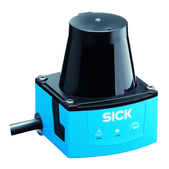
TiM31x
TiM32x
Detecting Laser Scanner
Short Range
Intended use
The laser scanner TiM31x/TiM32x (referred to as the TiM
below) is an intelligent sensor for invisibly detecting objects
in areas (fields) to be monitored. It is designed for mobile
or stationary interior use in stand-alone operation, with a
scanning range of up to 4 m. The combined triggering of the
four switching inputs activates one of the 16 field sets as an
evaluation case for performing field monitoring.
With the TiM31x, each configurable field set offers three
origin-oriented, partially overlapping fields of uniform shape,
but different sizes. Field sets with fixed or freely definable
shapes are available.
With the TiM32x each field set provides three configurable
fields.
The TiM signals detected field infringements in relation to the
three fields through a combination of three switching outputs.
The TiM is available in both a PNP and an NPN variant. The
NPN variant is identified by S02 in the type code on the type
label.
The purpose of this instruction manual is to allow you to put
the TiM into operation quickly and easily using preconfigured
8018590/YK97/2015-04-27 • Subject to change without notice • SICK AG • Waldkirch • Germany • www.sick.com
field sets and to obtain the first detection results.
Further information on the mechanical and electrical
installa-tion is available in the & Technical Information
(no. 8014318).
This document can be accessed on the TiM product website
(www.mysick.com/en/tim3xx).
The TiM is certified to IEC/EN/UL/CSA 61010-1:2007. These
operating instructions may contain passages of text in a
foreign language.
Safety information
• Read these instructions before commissioning the TiM
in order to familiarize yourself with the device and its
functions.
• Mounting and electrical installation are to be performed
only by qualified technicians.
• Electrical connections between the TiM and other devices
may only be made when there is no power to the system.
Otherwise, the devices may be damaged.
• Select and design conductor cross sections of the supply
cable from the customer's power system in accordance
with the applicable standards. If the supply voltage for the
TiM is not fed via the optional CDB730-001 connection
module, protect the TiM with an external 0.8 A delay-action
fuse at the start of the supply cable.
• All circuits connected to the TiM must be designed SELV
or PELV circuits. (SELV = Safety Extra Low Voltage, PELV =
Protective Extra Low Voltage).
• Use the device only under permitted environmental condi-
tions (e.g. temperature, grounding potential,
see "Technical specifications Page 5").
• Protect the TiM against moisture and dust when the cover
to the USB socket is open. To comply with the IP 65 enclo-
sure rating during operation, the black rubber plate must
be flush-mounted on the housing.
• Opening the screws of the TiM housing will invalidate any
warranty claims against SICK AG.
• The TiM does not constitute personal protection
equipment in accordance with the respective applicable
safety standards for machines.
Commissioning and configuration
Step 1: Electrical installation
1. Connect the 15-pin D-sub-HD connecting cable plug
with the corresponding socket of the connection modul
CDB730-001.
– or –
Connect the 12-pin M12 connecting cable plug to a
customer-side connection box. To do this, make a connec-
tion box with a 12-pin M12 socket. The box serves as the
connection module for feeding the supply voltage, and for
the signal routing of the switching inputs and outputs (
see "Electrical Installation" chapter in the & Technical
Information (no. 8014318)).
2. Connect the TiM's Micro USB socket (behind the black rub-
ber plate on the side) to a free USB socket (type A) on the
PC using a suitable shielded high-speed USB cable (e.g.
no. 6036106, 2 m). Do not extend the cable!
3. Supply power to the TiM.
Using the power supply unit it must be ensured that
the supply voltage does not drop below 8 V for longer
than 2 ms and never rises above 30 V.
Following successful initialization, the green LED lights up
▸
"
" (device ready for operation).
Do not supply the switching inputs with current yet.
Connection module
USB
USB
CDB730-001
...
...
SOPAS
SOPAS
"USB 2.0"
TiM
1 2
Configuration
Field monitoring
GND
Diagnosis
DC 9 ... 28 V
"Power/I/O"
Electrical block diagram for commissioning the TiM with a 15-pin D-Sub-
HD cable plug.
customer-
provided
OUT 1 OUT 3
USB
USB
OUT 2
SOPAS
SOPAS
"USB 2.0"
Connection
box
delay-
TiM
...
action
Configuration
fuse
Field monitoring
Diagnosis
0,8A/T
IN 1
IN 4
DC 9 ... 28 V
"Power/I/O"
Electrical block diagram for commissioning the TiM with a 12-pin M12
cable plug.
customer-
provided
OUT 1 OUT 3
USB
USB
OUT 2
SOPAS
SOPAS
Connection
„USB 2.0"
box
delay-
TiMxS02
...
action
Configuration
fuse
Field monitoring
0,8A/T
Diagnosis
IN 1 IN 4
IN
9 ... 28 V
DC 9 ... 28 V
„Power/I/O"
Electrical block diagram for commissioning the NPN variant with a 12-
pin M12 cable plug.
Step 2: Mounting and alignment
NOTE
During installation make sure there is no reflective surface
behind the reference target see "Device overview Page
4", point
.
â
1. Optional: mount the TiM to separately ordered mounting
accessories (mounting kit 2), see "Mounting" Chapter in
the & Technical Information (no. 8014318).
2. Otherwise, mount the two straight plates from the
enclosed mounting kit 1 on the TiM using two M3 screws.
Use the two blind-hole threads either on the underside or
back of the housing ( see "Device overview Page 4").
If the straight plates are not used, screw the screws
provided by the customer max. 2.8 mm into the thread.
3. Mount the TiM on a prepared bracket.
The device should be as free from vibration as possible
during operation.
4. Align the 90° axis of the TiM's scanning angle with the
center of the area to be monitored. The
marking on the
lid of the optical hood serves as a bearing alignment aid
( see "Device overview Page 4").
Scanning range in m (feet)
6
(19.69)
180°
4
225°
(13.12)
2
(6.56)
270°
90°
0
2
(6.56)
4
‒45°
(13.12)
0°
6
(19.69)
4
2
0
2
4
6
6
(19.69)
(13.12)
(6.56)
(6.56)
(13.12)
(9.69)
Scanning range in m (feet)
Scanning range max. 4 m (13.12 feet)
Scanning range for objects up to
10 % remission 2 m (6.56 feet)
Range diagram for TiM
a. Configuration without PC
Here, the TiM provides two options:
• Using one of 16 default field sets, each with 3 predefined
fields having the same field shape, but different sizes
• Teach-in of the surrounding contour to automatically
generate the outer field with any shape, including more
complex shapes, and to deduce the two inner fields.
The field sets are organized by groups into segmented field
shapes. The shapes can be modified, with the default being a
rectangle. In the factory setting, the 3 origin-oriented fields of
TiM31x/TiM32x | SiCK
1
Advertisement

Related Manuals for SICK TiM31x


Summary of Contents for SICK TiM31x
- Page 1 In the factory setting, the 3 origin-oriented fields of ber plate on the side) to a free USB socket (type A) on the 8018590/YK97/2015-04-27 • Subject to change without notice • SICK AG • Waldkirch • Germany • www.sick.com TiM31x/TiM32x | SiCK...
- Page 2 O = illuminated; = flashes Segmented, Rectangle The TiM stores the new field set 1 permanently. free shape type Field editor display window TiM31x/TiM32x | SiCK 8018590/YK97/2015-04-27 • Subject to change without notice • SICK AG • Waldkirch • Germany • www.sick.com...
- Page 3 If you wish to observe another field set, it must first be activated 8018590/YK97/2015-04-27 • Subject to change without notice • SICK AG • Waldkirch • Germany • www.sick.com TiM31x/TiM32x | SiCK...
-
Page 4: Device Description
Function button for teach-in Connecting cable outlet 0.9 m with 15-pin D-Sub HD plug or connecting cable 0.8 m with 12-pin M12-plug ('Power/Switching inputs/outputs' connection). 8018590/YK97/2015-04-27 • Subject to change without notice • SICK AG • Waldkirch • Germany • www.sick.com TiM31x/TiM32x... - Page 5 1) Default setting, starting shape can be modified as required 1 x 0.8 m cable (+10 %) with 12-pin M12 plug 2) TiM31x: Field 2 limits = field 1 limits plus 25 %, relationship cannot be changed • Heating of the cables with possible spontaneous...
- Page 6 The TiM is electronic waste and must under no circumstances be disposed of with general waste! 8018590/YK97/2015-04-27 • Subject to change without notice • SICK AG • Waldkirch • Germany • www.sick.com TiM31x/TiM32x | SiCK...
Need help?
Do you have a question about the TiM31x and is the answer not in the manual?
Questions and answers