Table of Contents

Related Manuals for GRAUPNER mz-12PRO HoTT


Summary of Contents for GRAUPNER mz-12PRO HoTT
- Page 1 Manual mz-12PRO HoTT 12 channel 2,4 GHz transmitter No. S1002.PRO Part 1...
- Page 2 2 / 36 S1002.PRO_sh_V2...
-
Page 3: Table Of Contents
Index Introduction ................5 Service center ................5 Intended use ................6 Target group ..................6 Package content ................ 6 Technical data ................7 Symbol description ..............7 Safety notes ................8 For your safety by handling the transmitter ........9 For your safety by handling the battery .........9 Description of the transmitter .......... - Page 4 Adjusting the control mode ............26 Display "USB connected" ..............28 Charge the battery ..............28 Joystick ..................28 PC COM Port ................28 Servo display ................29 Firmware update ..............32 Transmitter software update ............32 Restoring the transmitter software ..........33 SIMPLIFIED DECLARATION OF CONFORMITY ......34 Notes on environmental protection .........
-
Page 5: Introduction
Introduction Thank you very much for purchasing a Graupner mz-12 Pro HoTT transmitter. Read the manual carefully to use the transmitter optimally und first of all to safely control your models. If you experience any trouble during operation, take the instructions to help or ask your dealer or Graupner Service Centre. -
Page 6: Intended Use
The programming manual (manual part 2) can be found in its last version on www.graupner.de by the related item page. Note Graupner constantly works on the development of all products; we reserve the right to change the item, its technology and equipment. 6 / 36 S1002.PRO_sh_V2... -
Page 7: Technical Data
Technical data Transmitter mz-12 Pro HoTT Frequency band 2,4 … 2,4835 GHz Modulation FHSS Transmitting power 100 mW EIRP Control functions 12 functions of which 4 can be trimmed Temperature range -10 … +55 °C Antenna Integrated antenna 3.4 … 5.5 V Operating voltage Power consumption Approximately 180 ... -
Page 8: Safety Notes
Safety notes These safety instructions are intended not only to protect the prod- uct, but also for your own and other people’s safety. Therefore please read this section very carefully before using the product! • Do not leave the packaging material lying around, this could be a dangerous toy for children. -
Page 9: For Your Safety By Handling The Transmitter
For your safety by handling the transmitter WARNING Also while programming the transmitter, make sure that a motor connected in the model cannot accidentally start. Disconnect the fuel supply or drive battery beforehand. CAUTION Avoid every kind of short-circuit in all sockets of the transmitter and of the receiver! Risk of fire! Use only the suitable connectors. - Page 10 • Never charge batteries that have already been charged or hot ones. If a cell in a battery pack has become particularly hot fol- lowing a quick-charge process, this may indicate a defect in that cell. Do not use the battery pack any more! •...
-
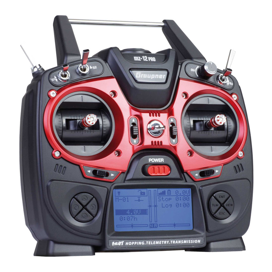
Page 11: Description Of The Transmitter
Description of the transmitter Control elements on the transmitter antenna integrated in the case Eyelet for neck strap Proportional dial DV 2 way switch SW 3 3 way switch SW 6 and 7, push-switch, latching-switch Right stick Right four way keys Trim ON/OFF switch Left four way keys... - Page 12 Case screws Battery case cover 3,5 mm jack to connect earphones or a DSC cable Data socket to connect a smart box Micro USB port, to use as: Charge port, update port, joystick function 12 / 36 S1002.PRO_sh_V2...
-
Page 13: Connections And Fixtures
Graupner therefore strongly recommends only using wireless simulators. Switch on the line "DSC output" of the menu "general Set." to DSC mode if necessary. -
Page 14: Transmitter Preparation
Transmitter preparation Adjusting the length of the control sticks Length of both control stick can be adjusted. Hold down the bottom half of the knurled grip, and loosen the screwed connection by turn- ing the top part. You can now lengthen or shorten the control stick by screwing it up or down. -
Page 15: Neutralizing The Control Sticks
Transmitter antenna integrated in the handle Adjust screws for brake spring (outer) and ratchet (inner) Stick self centering force adjust screws Screw to convert from neutralizing to non neutralizing and vice versa Neutralizing the control sticks Both control sticks can be set from neutralizing to non-neutralizing and vice versa. -
Page 16: Brake Spring And Ratchet
Brake spring and ratchet The outboard screw of the two marked in the figure adjust the brak- ing force. The inboard screw adjusts the strength of the ratchet for the respec- tive control stick. Note The left-hand control stick gimbal is specular to the left one, so that here the screws are located left on the top side. -
Page 17: Charge The Battery
0.5 A) which are common to USB2 ports. To do this, the included USB cable must be connected to a USB compatible charger. The charging process is shown through the red lightning Graupner text. The indication quits when, with switched off transmitter, the battery is full. -
Page 18: Starting Up The Transmitter
Starting up the transmitter At the factory, the first six model memories are preloaded with a Copter model from the Graupner product range so that each of these 6 models can be put into operation immediately after the binding of a receiver. -
Page 19: Use And Menu Functions
Use and menu functions Four-way keys Buttons to the left of the display Hereinafter referred to as left, right upper and lower selection keys. These keys are used to scroll through lists, columns, etc., in the same way as their arrow directions, and values are changed. Furthermore, •... -
Page 20: Short-Cuts
- Push the ESC or ENT key to move back to the base display. Note A complete description of the "Telemetry menu" and "Telemetry data display" can be found in the Part 2 of the manual available for download on www.graupner.de/Productpage. 20 / 36 S1002.PRO_sh_V2... - Page 21 • "HIDDEN MODE" Simultaneously press the left, the right and the lower selection keys of the four-ways key to open the "Hidden mode" menu from the base display of the transmitter as from almost every menu position. • Key lock The four-way keys can be locked by pushing simultaneously the TLM and VIEW keys for about 1 second in the base display.
-
Page 22: Display And Touchpad
Display and touchpad 5:1V M-01 Stop 0:00 GRAUBELE Flight 0:00 3.9V 1:23h 5.5V 4 11 Model name Memory 1 ... 250 Model type display Plane, helicopter, copter, truck, boat models Optical display of the trim position Flight chronometer in min:s (forward/reverse) Flight or drive chronometer in min:s (forward/reverse) Transmitter battery voltage (when a determined threshold is trespassed a warn mes-... -
Page 23: Function Field In The Display
Function field in the display Depending on the given menu, certain function fields will appear on the bottom display line. A marked function is activated by pushing the ENT key. (SET) SET SEL STO SYM ASY (SELECT) (STORE) Set values symmetrically Set values asymmetrically Switch symbol field (assignment of all types of switches) -
Page 24: Hidden Mode
Hidden mode Simultaneously press the left, the right and the lower selection keys HIDDEN MODE STICK CALIBRATION of the four-ways key to open the "Hidden mode" menu from almost every menu position. Stick calibration If the middle position of the self neutralizing control stick is not STICK CALIBR ATION exactly 0 ... -
Page 25: Binding A Receiver
Binding a receiver To establish a connection with the transmitter, Graupner HoTT Model M. Type Servo receivers must first be "bound" to at least one model memory in "its" memory phase setting setting Graupner HoTT transmitter. This process is generally called "bind- ing"... -
Page 26: Adjusting The Control Mode
Adjusting the control mode The transmitter is sent out of the factory with the control mode 2 Control mode software. That is the reason why also every new model memory will Receiver output Rx bind ––– be initialized with the control mode 2. Range test 99sec However, this default value can always be adapted to the user's own... - Page 27 (Copter) MODE 1 (Throttle/Pitch right) MODE 2 (Throttle/Pitch left) Nick Throttle/Pitch Throttle/Pitch Nick Nick Throttle/Pitch Throttle/Pitch Nick MODE 3 (Throttle/Pitch right) MODE 4 (Throttle/Pitch left) Nick Throttle/Pitch Throttle/Pitch Nick Nick Throttle/Pitch Throttle/Pitch Nick (Truck and boat models) MODE 1 (for/backward right) MODE 2 (for/backward left) forward/backward forward/backward...
-
Page 28: Display "Usb Connected
Display "USB connected" Charge the battery As long as a USB cable is connected to the switched-off transmitter and this is connected to a suitable USB power source, the transmit- ter is automatically charged until the battery is full. If the transmitter is switched on during a charging process, a selec- 0:0V tion menu appears in the display. -
Page 29: Servo Display
Servo display The graphical representation of the current servo position can be –100% recalled at any time by pushing the VIEW key of the right four-way keys from the base display so as from almost every other menu posi- tions. The current setting of each servo is displayed precisely between -150% and +150% of the normal path taking into account the control and servo settings, dual rate/expo functions, the interaction between... - Page 30 • For helicopter models, the display follows the assignment below: Bar 1 Pitch or roll (2) or nick (2) servo Bar 2 Roll (1) servo Bar 3 Nick (1) servo Bar 4 Tail servo (gyro) Bar 5 Nick (2) servo Bar 6 Throttle servo or governor Bar 7...
- Page 31 • The display follows the assignment below for trucks: Bar 1 Throttle/brake or forward/backward function Bar 2 Left/right function Bar 3 Free or special function Bar 4 Free or special function Bar 5 Free or special function Bar 6 Free or special function Bar 7 Free or special function Bar 8...
-
Page 32: Firmware Update
PC with Windows 7 ... 10. The required programs and files are enclosed in a software pack and can be found for the corresponding product at www.graupner.de. Download this software package from the Internet, and unpack it on your Windows PC or laptop. -
Page 33: Restoring The Transmitter Software
7. Select "Load automatically" or "Open file". 8. Select the "mz-12Pro_...bin" file. The data transfer to the transmitter begins. 9. The end of the data transfer will be indicated by the update pro- gram. The transmitter indicates the end of the transfer though the power on melody. -
Page 34: Simplified Declaration Of Conformity
SIMPLIFIED DECLARATION OF CONFORMITY Graupner/SJ hereby declares that the S1002.Pro mz-12 Pro HoTT complies with the Directive 2014/53/EU. The full text of the EU Declaration of Conformity is available at the following Internet address: www.graupner.de 34 / 36 S1002.PRO_sh_V2... -
Page 35: Notes On Environmental Protection
Internet at www.graupner.de on the relevant product page. In addition, the company Graupner/SJ has no responsibility or liability for any errors or inaccuracies that may appear in construction or operation manuals. Not liable for printing errors.
Need help?
Do you have a question about the mz-12PRO HoTT and is the answer not in the manual?
Questions and answers