Table of Contents
Advertisement
I NSTALLER :
Leav e th is m an ual with th e applian ce.
CONSUMER :
Retain th is m an ual f or f uture ref eren ce.
WARNING: If the information in these
instructions is not followed exactly a fi re or
explosion may result causing property
damage, personal injury or death.
FOR YOUR SAFETY
Do not store or use gasoline or other
fl ammable vapours and liquids in the
vicinity of this or any other appliance.
WHAT TO DO IF YOU SMELL GAS
•
Do not try to light any appliance.
•
Do not touch any electrical switch.
•
Do not use any phone in your building.
•
Immediately call your gas supplier
from a neighbour's phone. Follow the
gas supplier's instructions.
•
If you cannot reach your gas supplier
call the fi re department.
Installation and service must be per-
formed by a qualifi ed installer, service
agency or the gas supplier.
This appliance is suitable for installation in a
bedroom or bed sitting room.
This appliance is only for use with the type of
gas indicated on the rating plate. This
appliance is not convertible for use with
other gases unless a certifi ed kit is used.
This appliance is certifi ed for
use in Australia with Natural
Gas and Liquid Propane Gas.
This appliance is certifi ed
Gas Safety
for use in New Zealand with
Certi fi ed
Natural Gas only.
AS/NZS 5263.1.3
SAI-400322
060718-44
SERIAL #
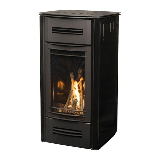
MIRAGE 18
INSTALLATION AND
OPERATING INSTRUCTIONS
MODEL: MI RAG E 1 8 , SERI ES: A
BALANCED FLUE FREE STANDING
GAS HEATER
MR18 AU
100000432-50
Advertisement
Table of Contents

Subscribe to Our Youtube Channel
Related Manuals for Pacific energy MIRAGE 18


Summary of Contents for Pacific energy MIRAGE 18
- Page 1 WHAT TO DO IF YOU SMELL GAS • Do not try to light any appliance. • Do not touch any electrical switch. MIRAGE 18 • Do not use any phone in your building. • Immediately call your gas supplier INSTALLATION AND from a neighbour’s phone.
-
Page 2: Table Of Contents
To access and remove the pilot assembly....... 35 Receiver ................13 Replacing the pilot assembly..........37 Lighting Instructions ..............14 Propane Conversion ..............39 Installing the Mirage 18 ............15 Maintenance ................40 Installation Checklist ............15 Glass Door: ..............40 Mirage 18 Dimensions ............. 16 Annual Inspection: ............ -
Page 3: Caution
Caution FOR YOUR SAFETY - Do not install or operate your Paci c Energy gas stove without rst reading and understanding this manual. Any installation or operational deviation from the following instructions voids the Paci c Energy ™ Warranty and may prove hazardous. This appliance and its individual shut off valve must be disconnected from gas supply piping system during any pressure testing of that system at test pressures in excess of 1/2 psig (3.5 kPa). -
Page 4: Safety
Safety Due to high temperatures, this gas appliance should be located out of traf c and away from furniture and draperies. Children and adults should be alerted to the hazards of high surface temperatures and should stay away to avoid burns or clothing ignition. Young children should be carefully supervised when they are in the same room as the appliance. -
Page 5: Warnings And Cautions
Warnings and Cautions • DO NOT SPRAY AEROSOLS IN THE VICINITY OF THIS APPLIANCE WHILE IT’S IN OPERATION. • DO NOT USE OR STORE FLAMMABLE MATERIALS IN OR NEAR THIS APPLIANCE. • DO NOT PLACE ARTICLES ON OR AGAINST THIS APPLIANCE. •... - Page 6 WARNING FIRE HAZARD. CAN CAUSE SEVERE INJURY OR DEATH. THE RECEIVER CAUSES IGNITION OF THE APPLIANCE. THE APPLIANCE CAN TURN ON SUDDENLY. KEEP AWAY FROM THE APPLIANCE BURNER WHEN OPERATING THE REMOTE SYSTEM OR ACTIVATING MANUAL BYPASS OF THE REMOTE SYSTEM. INSTALLATION AND REPAIR SHOULD BE DONE BY A QUALIFIED SERVICE PERSON.
-
Page 7: Operating Instructions
Operating Instructions Warning: The home owner must not make any adjustments to the appliance other than what can be achieved by using the remote handset (Figure 1) and the settings control / battery holder located at the bottom of the surround backing plate (Figure 20). -
Page 8: First Fire
First Fire When lit for the rst time, the gas stove will emit a slight odour for a couple of hours. This is due to the curing of paints, sealants and lubricants used in the manufacturing process. This condition is temporary. - Page 9 TRANSMISSION KEY LOCK LOW BATTERY ALARM THERMOSTAT OFF/ ON/SMART ROOM TEMPERATURE SMART CPI MODE SET POINT: TEMPERATURE/LEVEL/STATE FLAME ON COMFORT FAN Figure 2: Pro ame 2 LCD display. Attention! • Turn off the main gas supply for the appliance during installation or maintenance of the receiver/module device.
-
Page 10: Remote Transmitter Description
Remote Transmitter Description The Pro ame2 Remote Control consists of two elements: 1. Pro ame2 Remote Control Transmitter. 2. Pro ame Integrated Fireplace Control (IFC Module) board and a wiring harness to connect the IFC to the gas valve and stepper motor (Figure 43). Transmitter (Remote Control with LCD Display) The Pro ame 2 Transmitter uses a streamline design with a simple key layout and an informative LCD display (Figure 2). -
Page 11: Temperature Indication Display
Using the Remote Control Transmitter Temperature indication Display With the remote control transmitter in the “OFF” position, press the thermostat and mode keys at the same time. Look at the LCD screen on the remote control transmitter to verify that a C or F is visible to the right of the room temperature display (Figure 4 and Figure 5). -
Page 12: Room Thermostat (Transmitter Operation)
Room Thermostat (Transmitter Operation) The remote control transmitter can operate as a room thermostat. The thermostat can be set to a desired temperature to control the comfort level in a room. To activate this function, press the thermostat button (Figure 1), the LCD display on the remote control transmitter will change to show that the room thermostat is “ON”... -
Page 13: Continuous Pilot/Intermittent Pilot (Cpi/Ipi) Selection
Continuous Pilot/Intermittent Pilot (CPI/IPI) selection With the system in the “OFF” position, press the Mode Key (Figure 1) to index to the CPI mode icon (Figure 12). Pressing the Up Arrow Key will activate the Continuous Pilot Ignition mode (CPI). Pressing the Down Arrow Key will return to IPI. -
Page 14: Lighting Instructions
Serveiller les enfants. Garder les vêtements, le meubles, l'essence ou autres liquides produisant des vapeurs infl ammables loin de l'appareil. S'assurer que le brûleur et le compartiment des commandes sont propres. Voir les instructions d'installation et d'utilisation qui accompagnent l'appareil. MR18/G958 050615 5051.185 Figure 15: Mirage 18 Lighting Instructions. 060718-44 100000432-50... -
Page 15: Installing The Mirage 18
Installing the Mirage 18 Installation Checklist 1. Uncrate the Mirage 18. Examine for shipping damage and that the shipping list is complete. 2. Review the following: • Mirage 18 dimensions (page 16). • Locating the Stove (page 17). • Clearances to combustibles (page 18). -
Page 16: Mirage 18 Dimensions
Mirage 18 Dimensions Figure 16: Mirage 18 Dimensions. 060718-44 100000432-50... -
Page 17: Locating The Stove
101.6 mm 101.6 mm 25.4 mm Horizontal ueing Vertical ueing Vertical ueing 101.6 mm 25.4 mm 101.6 mm Vertical ueing Horizontal ueing 4” Vertical ueing 101.6 mm 25.4 mm Figure 17: Mirage 18 Common locations & minimum clearances. 060718-44 100000432-50... -
Page 18: Clearances To Combustibles
Clearances to Combustibles 406.5mm 915mm 101.6 mm 101.6 mm front 915mm Figure 18: Mirage 18 clearance to combustibles. Minimum Clearance to Combustible Materials Note on corner placement INTERIOR SIDE WALL 101.6 mm Refer to minimum clearances as shown in INTERIOR BACK WALL 101.6 mm... -
Page 19: Flue Terminal Minimum Clearances
Flue Terminal Minimum Clearances S ee note 3 op ena b le w ind ow d oor S ee note 2 T = F lue termina l = G a s meter S h a d ing ind ic a tes p roh ib ited a rea s for fl... -
Page 20: Co-Axial Flueing
Co-axial Flueing The Mirage 18 can be ued using co-axial components, and co-linear components for ueing through an existing replace and chimney. Maximum and minimum ueing lengths can be found on the ueing chart Figure 19. 9455 mm 9150 mm... -
Page 21: Flue Components
This replace is certi ed for use with 101.6mm x 168.275mm coaxial ue components only. It is per- mitted to only use Duravent certi ed ueing for this appliance. Gas and Electrical Connections Mirage 18 Electrical Rating: 240 Vac, 0.47 amp, 0.0373 kW Battery holder... -
Page 22: Gas Supply
Electrical connection Plug the provided IEC power cord into the receptacle at the rear of the unit as shown in Figure 20. The battery holder and manual “ON/REMOTE/ OFF” switch are also located here. See details of operation on page 10. Gas Supply Servicing of the stove can be performed from the rear of the unit by removing the access panel from the unit. -
Page 23: Gas Pressure Testing Procedure
Gas Pressure Check Gas Type Injector (mm) MIN / MAX Manifold Inlet Pressure (MJ/hr) Pressure (kPa) (kPa) Natural Gas 1.98 13.19 / 18.99 0,87 1.13 Propane 1.25 14.77 / 18.99 2.48 2.75 Gas Pressure Testing Procedure Note: To test the gas pressure, turn off the gas supply to the stove before loosening test point screws. -
Page 24: Firebox Panel Removal / Installation
Firebox Panel Removal / Installation Note: The burner tray needs to be removed before installation or removal of panels - See “Burner Kit/Media Installation/Removal” on page 25. Upper back panel Removal Right side Left side 1. After removing the burner panel panel Lower back... -
Page 25: Burner Kit/Media Installation/Removal
Begin by removing the exterior side panel on your right hand side as you face the Mirage 18 (Figure 47 on page 33). Remove the injector from the side wall of the Mirage 18 (Figure 28). Remove the glass media then remove the 4 screws (Figure 27) with a screwdriver, and remove the burner tray (Figure 27). -
Page 26: Optional Glass Media Installation
Optional Glass Media Installation Evenly spread a thin layer of crushed glass across the entire burner pan (Figure 30). Note: It is not necessary to use the entire bag of crushed glass. Use enough to cover the burner tray with a single layer. Any more can interfere with proper flame distribution. -
Page 27: Optional Log Media Installation
- (Figure 33). The stove is delivered with two media dividers - a large one for the Mirage 30 model (Figure 31), and a smaller one for the Mirage 18 model. The divider will be placed into the center of the burner basket (Figure 32) and is used to separate the pebbles and glowing embers. -
Page 28: Door Removal / Installation
Door Removal / Installation Removal 1. Lift the mesh screen cover up and pull away from unit (Figure 38). 2. Remove the 12 3/8” (9.525 mm) nuts (Figure 37) Carefully remove the glass retainer with the glass by tilting the top towards you. Securing nuts Installation 1. -
Page 29: Battery Installation
Battery Installation Figure 39: Receiver with battery holder and settings controls. Batteries are used for remote operation and as a backup in case of a power outage. For the Receiver: Install four double A batteries by removing the outer cover plate (if present), and the inner cover as shown in Figure 3929. -
Page 30: Air Adjustment
Air Adjustment Figure 42: Venturi fully closed. Figure 41: Venturi fully open. The venturi comes from the factory set to the closed position for use with natural gas. It will need to be adjusted toward the open position for use with propane. To adjust the venturi, the right hand side panel must be removed;... -
Page 31: Pilot Adjustment
Pilot Adjustment Figure 43: Valve & IFC module location. Verify the pilot ame by turning the adjustment screw, using a at-tip screwdriver, seen on the valve in Figure 4434. PILOT ADJUSTMENT PILOT MAIN GAS SCREW SOLENOID SOLENOID PRESSURE MANIFOLD PRESSURE INLET MODULATOR TEST POINT... -
Page 32: Comfort Fan Removal / Installation
Comfort Fan Removal / Installation Removal 1. Disconnect the power cord from the unit. 2. Remove 3 screws holding the side panel in place at the rear of the unit (Figure 49 on page 33) 3. Disconnect the power connections (Figure 45). 4. -
Page 33: Exterior Panel Removal/Installation
Removal The Mirage 18 cladding consists of four panels; the right and left (as seen from the viewers’ perspective), and an upper and lower panel inset with grills. To remove the panels for service reasons or to change to a different set of panels, begin by removing the mesh screen panel (Figure 48) so as not to accidentally damage the mesh screen. -
Page 34: Installation
Top positioning screw/post for right hand panel. Figure 54: Mirage 18 upper and lower front panels. Right hand secur- ing screw for upper front panel Figure 52: Upper attach points for side and upper panels. Right hand secur- ing screw for lower... -
Page 35: Pilot Assembly Replacement
Pilot Assembly Replacement To access and remove the pilot assembly. Figure 56: Empty rebox. Figure 57: Burner tray removal. 1. Turn off the Mirage and allow it to cool down before proceding. 2. At the rear of the Mirage, disconnect the power cord. 3. - Page 36 At the rear of the appliance: 11. Disconnect the main gas supply line (Figure 60). 12. Remove the rear screen located on the lower portion of the Mirage by removing its three screws. 13. Disconnect the gas supply line to the gas valve (Figure 62). It is not necesarry to disconnect the pilot gas line at this time since it will come out with the control panel once it’s removed and can be removed at that time.
-
Page 37: Replacing The Pilot Assembly
Figure 64: Control panel securing screws. Figure 65: Remove lower screw. Figure 66: Control panel extracted from the unit. Figure 67: Line in connections. Replacing the pilot assembly. Extracting the pilot assembly requires that the control module be partially removed so that there is room to withdraw and reinsert the pilot assembly wires and gas line, otherwise there is not enough room to work with. - Page 38 4. Remove the pilot assembly by guiding the pilot wires and pilot gas line out through the opening between the gas valve and the control module, and the opening which the pilot head sits. Take note of how the pilot gas line is routed through the control panel as the new pilot assembly gas line will have to be routed the same way.
-
Page 39: Propane Conversion
To convert the gas stove from natural gas to propane, the Figure 72: Mirage 18 Pilot. (GASC.LP18KIT) kit is required. This kit comes with new pilot and burner ori ce as well as a new pressure modulator for the valve. -
Page 40: Maintenance
Maintenance CAUTION: Turn off gas and electrical power supply (if applicable) and allow ample time for unit to cool before servicing appliance. It is recommended that the gas stove and its venting should be inspected at least once a year by a quali ed service person. -
Page 41: Replacement Parts
Replacement Parts Description 1. Replacement Control Module ............. 80002043 2. Replacement Gas Valve .............. 80000194 3. Replacement Pilot Assembly ............80000193 4. Replacement Remote Control ............. 80002044 5. Replacement Complete Gas Tray..........80002050 6. Replacement Blower Kit .............. 80002045 7. Replacement Burner ..............80000308 8. -
Page 42: Wiring Diagram
V e r i f y p r o p e r o p e r a t i o n a f t e r s e r v i c i n g . Figure 75: Electrical diagram for Mirage 18. 060718-44... -
Page 43: Rating Label
Rating Label V ENTED G AS FI REPLACE HEATER - L C - 3 18 NOT FOR USE WI TH SOLI D FUEL AS/NZ S 5 2 6 3 . 0 : 2 0 1 7 - G as Applian ces; AS/NZ S 5 2 6 3 . 1 . 3 : 2 0 1 6 G as Space Heatin g Applian ces. - Page 44 © 2018 Copyright Paci c Energy Fireplace Products LTD Reproduction, adaptation, or translation without prior written permission is prohibited, except as allowed under the copyright laws. For tech n ical support, please con tact your retailer. Pacific Energy Australia PTY LTD. Web site: www.pacificenergy.net 120 Victoria Street, North Geelong, Victoria...
Need help?
Do you have a question about the MIRAGE 18 and is the answer not in the manual?
Questions and answers