
Related Manuals for Taylor H60


Summary of Contents for Taylor H60
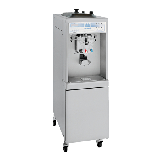
- Page 1 OPERATOR’S MANUAL Model H60 Shake Freezer Original Operating Instructions 055165- M 6/01/01 (Original Publication) (Updated 6/26/15)
- Page 2 Phase Maximum Fuse Size: Minimum Wire Ampacity: E Taylor Company 055165- M Any unauthorized reproduction, disclosure, or distribution of copies by any person of any portion of this work may be a violation of Copyright Law of the United States of America and other countries, could result in the awarding of Statutory Damages of up to $250,000 (17 USC 504) for infringement, and may result in further civil and criminal penalties.
-
Page 3: Table Of Contents
..............H60 Door and Beater Assembly . - Page 4 Copyright Law of the United States of America and other countries, could result in the awarding of Statutory Damages of up to $250,000 (17 USC 504) for infringement, and may result in further civil and criminal penalties. All rights reserved. Taylor Company 750 N. Blackhawk Blvd. Rockton, IL 61072 Table of Contents Model H60...
-
Page 5: To The Installer
Taylor equipment. This unit must NOT be installed in an area Only authorized Taylor service personnel where a water jet or hose can be used. NEVER use a should perform installation and repairs on the water jet or hose to rinse or clean the unit. -
Page 6: Air Cooled Units
The installation location is refer to the applicable National, State, and local codes marked by the equipotential bonding symbol (5021 of for determining the proper configuration. IEC 60417- 1) on the removable panel and the frame. 120416 To the Installer Model H60... -
Page 7: Beater Rotation
Beater rotation must be clockwise as viewed looking into the freezing cylinder. Taylor reminds technicians to be cautious of government laws regarding refrigerant recovery, NOTE: The following procedures should recycling, and reclaiming systems. If you have any questions regarding these laws, please contact the be performed by a trained service technician. -
Page 8: To The Operator
Taylor Distributor, and only if all required service work is provided by an authorized Taylor It should also be noted that Taylor does not warrant the service technician. Taylor reserves the right to deny refrigerant used in its equipment. For example, if the... -
Page 9: Safety
We, at Taylor Company, are concerned about the safety of the operator at all times when they are coming in contact with the unit and its parts. Taylor makes every effort to design and manufacture built- in All repairs should be performed by an safety features to protect both operators and service authorized Taylor service technician. - Page 10 78 dB(A) when measured at a distance of 1.0 experience with the unit, in particular as far as safety meter from the surface of the unit and at a height of 1.6 and hygiene are concerned. meters from the floor. 131105 Safety Model H60...
-
Page 11: Operator Parts Identification
Section 4 Operator Parts Identification 140611 Model H60 Operator Parts Identification... - Page 12 H60 Exploded View Parts Identification ITEM DESCRIPTION PART NO. ITEM DESCRIPTION PART NO. KIT A.- COVER- HOPPER X65369 O- RING- .291 ID X .080W 018550 AGITATOR A.- MIX HOPPER X44797 TUBE A.- FEED- SC- INNER X32824- 5 PANEL- SIDE *LEFT...
-
Page 13: H60 Door And Beater Assembly
H60 Door and Beater Assembly ITEM DESCRIPTION PART NO. ITEM DESCRIPTION PART NO. SEAL- DRIVE SHAFT 032560 O- RING- 1- 1/16 OD X.139W 020571 SHAFT- BEATER 035527 NUT- STUD 021508 BEATER A.- 7QT- 1 PIN X46233 TUBE- VINYL 3/16IDX5/16 R30314... -
Page 14: H60 Syrup Tank - 045533
H60 Syrup Tank - 045533 ITEM DESCRIPTION PART NO. ITEM DESCRIPTION PART NO. TANK- SYRUP- 4 QT. 045533 4a** RESTRICTOR- SYRUP 030917 COVER- TANK W/ FTG 035759- 1 4b** GASKET- RUBBER 023551 TIP- NYLON- WHITE TRANSL. 042747* O- RING- 5/8 OD X .103W 016030 O- RING- 3.437 ID X .275 W... -
Page 15: Accessories
Accessories ITEM DESCRIPTION PART NO. ITEM DESCRIPTION PART NO. BRUSH-MIX PUMP BODY - 023316 BRUSH-DRAW VALVE 014753 3” X 7” WHITE LUBRICANT-TAYLOR HI PERF 048232 BRUSH-END-DOOR-SPOUT 039719 PAIL-10 QT. 013163 KIT A.-TUNE UP X34615 SANITIZER·KAY-5·200·PKTS 041082 BRUSH-DOUBLE ENDED 013072 SANITIZER-STERA SHEEN-GR 055492 100 (2 OZ.) PKTS... -
Page 16: Important: To The Operator
= AUTO To better communicate in the International arena, the = MENU words on many of our operator switches and buttons have symbols to indicate their functions. Your Taylor = CHOCOLATE equipment is designed with these International symbols. = STRAWBERRY The following chart identifies the symbol definitions used on the operator switches. -
Page 17: Power Switch
When placed in the ON position, the power switch allows control panel operation. The power switch is Four shake flavors are offered from the Model H60 located on the left side of the control channel. freezer: chocolate, strawberry, vanilla (unflavored product), and an optional flavor. -
Page 18: Operating Screen Descriptions
October 31st. POWER SWITCH OFF MODE: WSH- PMP MIX: OUT TIME: 4:30 MIX: LOW HOPPER: 62.1 HOPPER TEMP: 40.0 F BARREL: 67.7 BRUSH CLEAN ON: 10/31 Important: To the Operator Model H60... - Page 19 41_F (5_C). If the product fails to cool in two every 14 days. Brush cleaning is the normal hours, the freezer will lock out. disassembly and cleaning procedures. Failure to 070316 Model H60 Important: To the Operator...
- Page 20 LED will light. If the to occur, or a heat cycle failure not due to a freezer is unlocked by brush cleaning, the mix low and thermistor failure.) mix out LED’s will light. Important: To the Operator Model H60...
-
Page 21: Operator Menu
FAULT DESCRIPTION if a power failure firmly. Clear the tone per instructions in has occurred. Clear the tone per instructions in “Clearing Fault Tones” on page 17. “Clearing Fault Tones” on page 17. 060807 Model H60 Important: To the Operator... - Page 22 (other than during the cooling phase of the unit. heat treatment cycle). SOFTWARE VERSION VISC HOPPER BARREL H60 Control UVC2 38.5 28.5 Version 2.03 TIME C 11:00 11:00 081111 Important: To the Operator...
- Page 23 Power switch placed in the OFF position. Mix Low Condition. 14 Day Timeout Occurred. Screen “K” is the SERVICE MENU. This screen can Heat Cycle Record Cleared. only be accessed by a service technician. 150206 Model H60 Important: To the Operator...
- Page 24 To exit the STANDBY mode and place the unit in AUTO, press the AUTO key once. Pressing the AUTO key again will place the unit in the OFF mode. Important: To the Operator Model H60...
-
Page 25: Operating Procedures
Section 6 Operating Procedures The Model H60 has one 7 quart (6.6 liter) freezing cylinder. This automatic freezer offers four separate flavors which are blended and ejected from one spout. (Use only single strength syrup that is free of pulp and seeds.) - Page 26 Place the white plastic guide bearing over the front holding pin. Slide the beater assembly on the rear of the rotor shaft. DO NOT lubricate plastic completely into the freezing cylinder. guide bearing. 150626 Operating Procedures Model H60...
- Page 27 Replace any damaged parts. Step 5 Lubricate the plastic spinner bearing. Insert the plastic spinner bearing into the top of the draw valve. Figure 10 150626 Model H60 Operating Procedures...
- Page 28 Insert the spinner blade from the bottom into the center of the draw valve until the shaft appears at the top of the draw valve. Figure 12 Step 7 Slide the drip pan into the hole in the front panel. Figure 15 Operating Procedures Model H60...
- Page 29 Check the torque arm by moving it back and forth to be sure it moves freely and easily. Step 11 Connect the syrup lines of the spinner housing to the quick disconnect fittings on the front panel. Figure 20 Model H60 Operating Procedures...
-
Page 30: Sanitizing
Place the power switch in the ON position. Step 5 Press the WASH key and allow the sanitizing solution in the freezing cylinder to agitate for five minutes. Figure 22 Figure 23 080627 Operating Procedures Model H60... -
Page 31: Priming
Place the inner air tube inside the outer air tube and lay When full strength mix is flowing from the dispensing in bottom of mix hopper. spout, close the draw valve. Figure 25 Figure 27 150626 Model H60 Operating Procedures... -
Page 32: Daily Closing Procedures
Note: Pressing the left arrow key will stop the agitator rotation for ten seconds. Figure 29 Step 4 Fill the hopper with fresh mix and place the mix hopper cover in position. Note: Use only FRESH mix when priming the freezer. Figure 30 150626 Operating Procedures Model H60... - Page 33 AUTO mode. Discard from entering the freezing cylinder during the heating product and brush clean machine. and standby process. Figure 31 010917 Model H60 Operating Procedures...
-
Page 34: Daily Opening Procedures
Dip the end brush into the sanitizing solution Step 6 and brush clean the door spout and bottom of the draw Press the AUTO key to resume normal operation. valve. When the unit cycles off, product is ready to serve. 080627 Operating Procedures Model H60... -
Page 35: Syrup System
Using a flat blade screwdriver, turn the adjusting screw clockwise. Repeat this step for all syrup tanks. Verify syrup calibration. Tighten the lock nut after the Note: Refer to page 34 for sanitizing syrup tanks. correct calibration is achieved. Model H60 Operating Procedures... -
Page 36: Manual Brush Cleaning
Take these parts to the sink for cleaning. Step 3 Remove the hopper cover, agitator, and assembled air tube from the mix hopper. Take these parts to the sink for cleaning. Figure 35 Operating Procedures Model H60... -
Page 37: Hopper Cleaning
MILD of a solution will not provide adequate close the draw valve and press the WASH key cleaning. Make sure all brushes provided with the cancelling wash cycle. freezer are available for brush cleaning. 140717 Model H60 Operating Procedures... -
Page 38: Sanitizing The Syrup System
Thoroughly brush clean the dip tube, syrup line fitting, Note: If the drip pan is filled with an excessive amount and o- ring using the sanitizing solution. Reassemble of mix, refer to the Troubleshooting Guide. the dip tube, o- ring, and syrup line fitting. Operating Procedures Model H60... - Page 39 The fourth syrup line is for the spinner rinse. Press the Press the CALIBRATE key. A message will appear on RINSE key to further flush this rinse line. Place the the LCD. power switch to the OFF position. Model H60 Operating Procedures...
-
Page 40: Important: Operator Checklist
8. The temperature of the mix in the mix hopper maintenance purposes. Deteriorated and the walk- in cooler should be below 40_F. cracked water lines should be replaced only by (4.4_C.). an authorized Taylor mechanic. 051208 Important: Operator Checklist Model H60... -
Page 41: Winter Storage
Disconnect the freezer from the main power source to prevent possible electrical damage. If the place of business is to be closed during the winter Your local Taylor Distributor can perform this service months, it is important to protect the freezer by for you. -
Page 42: Troubleshooting Guide
The freezer must now be disassembled and brush cleaned. f. The agitator is not f. The agitator must be cleaned before starting rotating. the heat cycle. Disassemble the freezer and brush clean. Troubleshooting Guide Model H60... - Page 43 Not enough syrup is being d. Calibrate the syrup system. Syrup delivery blended with product. should be 1 oz. (29.6 ml) in six seconds. e. Torque arm not installed. e. Install torque arm. Model H60 Troubleshooting Guide...
- Page 44 The temperature is out of a. Call a service technician - - - to adjust hopper too warm while in the adjustment. temperature. AUTO mode. b. The hopper cover is not in b. Place the cover in position. position. Troubleshooting Guide Model H60...
- Page 45 There is unadequate b. Lubricate properly. lubrication on the draw valve o- rings. c. The wrong type of c. Use food grade lubricant (Example: Taylor Lube lubricant was being used High Performance). (Example: petroleum base lubricant). 12. Excessive mix leakage a.
- Page 46 Assembled air tubes c. Install in mix inlet hole, using end with the hole in installed incorrectly. it. Pin on inner air tube must be positioned at the bottom of the notch in the outer air tube. Troubleshooting Guide Model H60...
-
Page 47: Parts Replacement Schedule
Minimum Necessary White Bristle Brush, 1- 1/2” x 2” Inspect & Replace if Minimum Necessary White Bristle Brush, 3” x 7” Inspect & Replace if Minimum Necessary End Brush Inspect & Replace if Minimum Necessary Model H60 Parts Replacement Schedule... -
Page 48: Section 10 Limited Warranty On Equipment
Taylor, through an authorized Taylor distributor or service agency, will provide a new or re- manufactured part, at Taylor’s option, to replace the failed defective part at no charge for the part. Except as otherwise stated herein, these are Taylor’s exclusive obligations under this limited warranty for a Product failure. - Page 49 LEGAL REMEDIES The owner must notify Taylor in writing, by certified or registered letter to the following address, of any defect or complaint with the Product, stating the defect or complaint and a specific request for repair, replacement, or other correction of the Product under warranty, mailed at least thirty (30) days before pursuing any legal rights or remedies.
-
Page 50: Limited Warranty On Parts
Taylor warrants the Parts against failure due to defect in materials or workmanship under normal use and service as follows. All warranty periods begin on the date of original installation of the Part in the Taylor unit. If a Part fails due to defect during the applicable warranty period, Taylor, through an authorized Taylor distributor or service agency, will provide a new or re- manufactured Part, at Taylor’s option, to replace the failed defective Part at no... - Page 51 Parts or the units in which they are installed repaired or altered in any way so as, in the judgment of Taylor, to adversely affect performance, or normal wear or deterioration.
-
Page 52: Rockton, Il
LEGAL REMEDIES The owner must notify Taylor in writing, by certified or registered letter to the following address, of any defect or complaint with the Part, stating the defect or complaint and a specific request for repair, replacement, or other correction of the Part under warranty, mailed at least thirty (30) days before pursuing any legal rights or remedies.
Need help?
Do you have a question about the H60 and is the answer not in the manual?
Questions and answers