Table of Contents
Advertisement
Quick Links
Advertisement
Table of Contents
Troubleshooting

Related Manuals for Instrutech The Hornet IGM402


Summary of Contents for Instrutech The Hornet IGM402
- Page 1 InstruTech® Hot Cathode Ionization Vacuum Gauge With Dual Convection IGM402 Module The Hornet™ User Manual InstruTech 1475 S. Fordham St. Longmont, CO 80503 Phone: +1-303-651-0551 Fax: +1-303-678-1754 E-mail info@instrutechinc.com www.instrutechinc.com p/n 000861-116...
- Page 2 In no event will InstruTech be responsible or liable for indirect or consequential damages that result from the use or application of this equipment.
- Page 3 Instruction Manual IGM402 Hornet Copyright © 2011 by InstruTech All rights reserved. No part of this work may be reproduced or transmitted in any form or by any means, electronic or mechanical, including photocopying and recording, or by any information storage or retrieval system, except as may be expressly permitted in...
-
Page 4: Table Of Contents
RS485 COM / Relay Connector pin-out for IGM402 ..............16 3.3.2.3 Analog output and setpoint relays for CG1 and CG2 ..............17 Bakeout ................................18 Bakeout - Ionization gauge sensor ......................18 Bakeout - Convection vacuum gauges CG1 and CG2 ................18 InstruTech Page 2... - Page 5 Effects of different gases on convection gauge display ................48 7.2.1 Convection gauge display conversion for selected gases ..............50 Effect of different gases on analog output ....................52 7.3.1 Ion gauge analog output correction factors for selected gases ............52 InstruTech Page 3...
- Page 6 Troubleshooting - Error Messages ......................75 Troubleshooting - Filaments F1 or F2 open ..................... 76 R & D (Research) Diagnostic Display ......................77 Maintenance ............................79 Contamination ............................79 Sensor Replacement..........................81 Factory Service and Support ..........................82 Warranty ................................82 InstruTech Page 4...
-
Page 7: Introduction / General Information
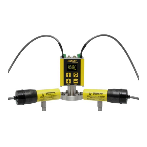
The InstruTech® IGM402 Hornet™ module provides the basic signal conditioning required to turn a hot cathode ionization vacuum gauge into a complete measuring instrument. In addition, the IGM402 is capable of operating two external convection vacuum gauges simultaneously. -
Page 8: Dimensions
20 to 28 Vdc, 30 W protected against power reversal and transient over-voltages connectors (2) 9-pin D-Sub, (2) terminal blocks, (2) convection gauge connectors convection gauge compatibility InstruTech CVG101 Worker Bee™ or Granville-Phillips ® 275 Convectron ® CE compliance... -
Page 9: Options & Accessories
24 Vdc @ 2.5 A (60 W) Connector: 9-pin D-sub female to mate with and power the IGM401 module Cable length: 6 ft. (2 m) Note: 9-pin D-sub connector backshell can be opened to enable connections to signals and relays InstruTech Page 7... -
Page 10: Important Safety Information
IGM402 Hornet Important Safety Information InstruTech has designed and tested this product to provide safe and reliable service, provided it is installed and operated within the strict safety guidelines provided in this manual. Please read and follow all warnings and instructions. -
Page 11: Safety Precautions - Igm402 Service And Operation
This will be more problematic in dirty applications. Use an appropriate power source of 20 to 28 Vdc, 30 W min. (InstruTech PS501 power supply is rated 60 W). Turn off power to the unit before attempting to service the module. Turn off power to the unit before detaching the electronics from the sensor for sensor replacement or bake-out purposes. -
Page 12: Safety Precautions - Cvg101 Service And Operation
Instruction Manual IGM402 Hornet Do not use if the unit has been dropped or the enclosure has been damaged. Contact InstruTech for return authorization and instructions for returning the product to InstruTech for evaluation. Use yttria coated filaments with air and inert gases such as N , argon, etc. -
Page 13: Proper Equipment Grounding
Never expose the gauge tube internal volume to pressure above local atmospheric pressure when using hazardous gases. InstruTech Page 11... -
Page 14: Gases Other Than Nitrogen / Air
WARNING! Do not attempt to use with gases other than nitrogen (N ) or air without referring to correction factor data tables. InstruTech gauges and modules are calibrated for direct readout of nitrogen or air. Do not attempt to use with other gases such as argon (Ar) or carbon dioxide (CO... -
Page 15: Mechanical Installation - Cvg101 Convection Gauge
PTFE (Teflon®) tape and hand tighten the gauge into the gauge port. Do not use a wrench or other tool which may damage the gauge. InstruTech Page 13... -
Page 16: Electrical Installation
2. 9-pin D-sub female (DE-9S) connector for RS485 serial communications and ion gauge relay connections. IGM402 I/O Interface When using InstruTech’s power Supply PS501A, connect the power supply to the ANALOG connector. If using a power supply other than InstruTech’s PS501A, connect your power supply to either the RS485 or the ANALOG connector as shown on the next page. -
Page 17: 3.3.2.1 Analog Connector Pin-Out For Igm402
When reading the context under the section of the table above titled PIN DESCRIPTION, references to “ground” are relative to pin 2 of the ANALOG I/O connector which is the Power Ground or power supply common connection. InstruTech Page 15... -
Page 18: 3.3.2.2 Rs485 Com / Relay Connector Pin-Out For Igm402
RS485 COM / IG Setpoint Relay 9-Pin D-sub female (DE-9S) connector NOTICE Do not connect power to both connectors. Furthermore, if you are using InstruTech’s PS501-A power supply and using the RS485 function do not connect power to pins 2 and 4 of the RS485 COM connector. -
Page 19: 3.3.2.3 Analog Output And Setpoint Relays For Cg1 And Cg2
IGM402 I/O Terminal Blocks for CG1, CG2, RELAY A and RELAY B section 5.8.4. – ASSIGN RLY A and ASSIGN RLY B for details on programming the CG device assigned to control RLY A and RLY B. InstruTech Page 17... -
Page 20: Bakeout
7. Reattach the electronics enclosure. Reinstall the screws (4 ea.) Bakeout - Convection vacuum gauges CG1 and CG2 The InstruTech Worker Bee convection vacuum gauges CG1 and CG2 can be baked out to 150 C. The CG1 and CG2 connectors and cables must be removed prior to bake out. -
Page 21: Setup And Operation
IGM402 that you intend to connect to. Alternatively, you can power the device by connecting InstruTech’s PS501-A power supply to the ANALOG connector of the IGM402. When you connect power, the display will show “UNIT STATUS OFF”. This indicates the display is on but the filament is not turned on and the sensor has not been activated yet. -
Page 22: Degas
For example, processes such as ion implantation may use tungsten filaments. Be aware that corrosive applications are hard on any filament and filament life will be reduced when operating in such environments. Tungsten filaments are easily damaged by exposure to air/oxygen during InstruTech Page 20... -
Page 23: User Interface Basics
Press the MENU key to return to the previous menu or, if necessary, press repeatedly to return to the main pressure measurement display screen. To continue Programming soft-keys setting additional parameters, scroll with the UP and DOWN keys until you reach the desired parameter. InstruTech Page 21... -
Page 24: Factory-Set Default Parameters
- RLY B LO TRP [Factory default = 1.00E-1 TORR] - RLY B HI TRP [Factory default = 2.00E-1 TORR] - RELAY B TEST [Factory default = OFF] - ASSIGN RLY A [Factory default = CG1] - ASSIGN RLY B [Factory default = CG2] InstruTech Page 22... - Page 25 - ADDR [Factory default = 1] - ADDR OFFSET [Factory default = 0] - FORMAT [Factory default = BINARY] SERVICE MENU - INFO [Factory default = FIRMWARE VERSION] - OP TIME [Factory default = Displays to-date operating time] InstruTech Page 23...
-
Page 26: Programming
ANALOG OUTPUT sections. Quick reference to the augmented top-level, main SETUP COMMS Top-Level Program Menu… in section 5.8.2 SERVICE MENU menu is found at EMISSION SEL DEGAS OFF DEGAS ON InstruTech Page 24... -
Page 27: Setup Disp
Ex 1A: Ionization Gauge data displayed in SHOW ALL LG mode The ionization gauge display screen (Example Ex 1A) above is followed by the next screen below showing the convection gauge 1 (CG1) data after the display interval time has elapsed. InstruTech Page 25... - Page 28 2 (CG2) is 760 Torr. Negative Exponent CG1 Measured Pressure IG: 6.45E-9 CG1: 1.23E-2 Ion Gauge Measured Pressure CG2: 760 Indicates Pressure Unit TORR CG2 Measured Pressure Ex 2A: IG, CG1 and CG2 data displayed in SHOW ALL SM mode InstruTech Page 26...
- Page 29 Example Ex 1A. This is followed by the second screen showing the convection gauge 2 (CG2) data as shown in Example Ex 1C. The screens repeat each time the programmed display interval time has elapsed. The convection gauge 1 (CG1) data is not displayed. InstruTech Page 27...
- Page 30 1.5 Vdc and filament current is 1.9 amperes. Negative Exponent Emission current value(A) Measured Pressure PT= 1.00E-9 IE= 4.00E-3 Ion current value (A) IC= 4.00E-11 Filament Voltage (Vdc) FVI 1.5 1.9 Filament current (amperes) Ex 10A: IG data displayed in IG ONLY RND mode InstruTech Page 28...
-
Page 31: Setup Unit
The CLR IG ERROR allows the user to clear the IG error using the front panel soft-keys, regardless of whether the IG CNTL mode below is set to Front Panel, Digital Input or RS485. InstruTech Page 29... - Page 32 RS485. The program code control logic is such that when switching from DIGI controls to RS485 controls, the device will invoke a ‘safe state’ if any RS485 command is sent to switch from DIGI to RS485. A InstruTech Page 30...
- Page 33 IG filament is in the ON state by pressing the ENTER key after selecting DEGAS ON in the main TOP-LEVEL Program Menu. The device will respond immediately after the ENTER key is pressed for either DEGAS ON or DEGAS OFF. InstruTech Page 31...
- Page 34 (ANALOG connector contact 8) to power ground (circuit common) available at pin 2 of the ANALOG (DE-9P) connector of the IGM402 while operating in the CG1 CNTL IG control mode. InstruTech Page 32...
-
Page 35: Setup Ig
RLY I HI TRP, the IGM402 will revert back to the original RLY I LO TRP value. To do this correctly so that the IGM402 will accept the new setting for the RLY I LO TRP, you must first select the InstruTech Page 33... - Page 36 F1: # H (Number of hours filament 1 has been in use). F2: # H (Number of hours filament 2 has been in use). D1: # H (Number of hours filament 1 has been degassed). D2: # H (Number of hours filament 2 has been degassed). InstruTech Page 34...
-
Page 37: Setup Cgs
In the SETUP CGS descriptive narrative of this section 5.8.4., the default settings are assumed, where RLY A is assigned to CG1 and RLY B is assigned to CG2. See ASSIGN RLY A/B instructions related to changing the assignment of either relay A/B to either CG1/CG2. InstruTech Page 35... -
Page 38: 5.8.4.1 Setup Cg1
(SET VACUUM). See SET ATM below. Failure to do so will result in improper operation of the gauge. If you change units of measure or reset to factory defaults, then this same procedure must be followed again if the units of measure are being set to either mbar or Pa. InstruTech Page 36... - Page 39 ANALOG TYPE - SET VAC InstruTech advises that you first determine if the ‘span’ (ATM) adjustment of your measurement device is set properly before setting the ‘zero’ (VAC) adjustment. It is good practice to perform the sequence of checking and adjusting ATM (span) then VAC (zero) and then, finally re-checking the ATM setting to ensure the instrument has been properly set.
-
Page 40: 5.8.4.2 Setup Cg2
Note - As you adjust the analog output, the number you are changing in the analog output calibration screen represents the millivolts offset from zero volts that is being used internally for the analog output gain adjustment. InstruTech Page 38... - Page 41 -CG2 ANALOG CAL [Factory default = Factory Set] Same as CG1 ANALOG CAL above except for CG2. InstruTech Page 39...
-
Page 42: Setup Comms
CRC8 error checking capability used in the original IGM402 design. The ASCII setting is for use with the InstruTech ASCII protocol format used in other product designs like the IGM401 Hornet and the CVM201 Super Bee. We recommend using the ASCII protocol whenever possible. The BINARY protocol is uncommon, difficult to use and not compatible with readily available PLCs. -
Page 43: Activating The Ig Sensor
CG1 and CG2 - Non-linear 0.375 to 5.659 Vdc The Analog Output voltage type described below represent the pressure displayed for nitrogen / air only. Refer section 7 if you are using a gas other than nitrogen/air. InstruTech Page 41... -
Page 44: Ion Gauge Analog Output - Ig Only
See the conditions listed above which will cause the output to switch to >10VDC. These conditions are listed immediately above this chart on this page. 1.0E-10 1.0E-09 1.0E-08 1.0E-07 1.0E-06 1.0E-05 1.0E-04 1.0E-03 1.0E-02 1.0E-01 1.0E+00 Pressure (Torr) InstruTech Page 42... -
Page 45: Ion Gauge Plus Convection Gauge Analog Output - Ig + Cg1
X-axis with a log scale; the output signal is plotted on the Y-axis on a linear scale. Log-Linear Analog Voltage to Pressure 1.0E-10 1.0E-09 1.0E-08 1.0E-07 1.0E-06 1.0E-05 1.0E-04 1.0E-03 1.0E-02 1.0E-01 1.0E+00 1.0E+01 1.0E+02 1.0E+03 Pressure (Torr) InstruTech Page 43... -
Page 46: Convection Gauge Analog Output - Log-Linear
2.0E+02 7.301 6.000 3.0E+02 7.477 4.0E+02 7.602 5.000 5.0E+02 7.699 6.0E+02 7.778 4.000 7.0E+02 7.845 7.6E+02 7.881 3.000 8.0E+02 7.903 2.000 9.0E+02 7.954 1.0E+03 8.000 1.000 0.000 1.0E-04 1.0E-03 1.0E-02 1.0E-01 1.0E+00 1.0E+01 1.0E+02 1.0E+03 Pressure (Torr) InstruTech Page 44... -
Page 47: Convection Gauge Analog Output - Non-Linear
X = 0.3840 volts A = -0.02585, b=0.03767, c=0.04563, d=0.1151, e=-0.04158, f=0.008738 y(x) = Pressure = 1.0E-03 Torr The equations listed above are used to calculate the non-linear voltage outputs for N /air shown in the table below. InstruTech Page 45... - Page 48 (though in recent years, some GP controllers produced a different 1.0E-03 0.3840 S-curve) 2.0E-03 0.3927 5.0E-03 0.4174 The non-linear output from InstruTech convection gauges, 1.0E-02 0.4555 modules, and controllers duplicates exactly the original S-curve of 2.0E-02 0.5226 0.375 to 5.659 Vdc for 0 to 1000 Torr. 5.0E-02 0.6819...
-
Page 49: Using The Gauge With Different Gases
Compensating the pressure reading using the Sensitivity adjustment method may not be possible for certain gases if the sensitivity correction factor results in a calculated sensitivity outside the adjustment range possible. InstruTech Page 47... -
Page 50: Ion Gauge Display Correction Factors For Selected Gases
(N ) and the gas in use. The charts and tables on the following pages indicate how different gases affect the display and output from an InstruTech convection gauge. InstruTech... - Page 51 The X-Axis is the pressure reading indicated by the convection gauge under test. The chart above shows readings for an InstruTech’s CVG101 convection gauges as well as for a Granville-Phillips® Convectron® gauge, to illustrate that the response of both these type of gauges is virtually the same.
-
Page 52: Convection Gauge Display Conversion For Selected Gases
Post a warning label on your gauge readout "Do Not Exceed ____ Torr Indicated Pressure" (fill in the blank for maximum indicated pressure for the gas you use) so that an operator using the gauge will not exceed a safe pressure. InstruTech Page 50... - Page 53 5.08E+0 1.11E+1 1.27E+1 Values listed under each gas type are in Torr units. OP = Overpressure Example: If the gas is argon (Ar), when the true pressure is 100 Torr, the gauge will read about 9 Torr. InstruTech Page 51...
-
Page 54: Effect Of Different Gases On Analog Output
��.�� ×���� −�� P (argon) = Torr true pressure of argon gas ��. ���� × ���� ��.���� The correction factor must be applied to the analog output over the entire pressure range measured by the ion gauge. InstruTech Page 52... -
Page 55: Ig + Cg1 Analog Output Correction Factors For Selected Gases
1 × 10 −�� �� ×���� −�� P (argon) = Torr true pressure of argon gas ��. ���� × ���� ��.���� The same correction factor must be applied over the entire pressure range as measured by the ion gauge. InstruTech Page 53... -
Page 56: Ig + Cg1 Analog Output Correction Factors - Convection Gauge Range
1.00E+3 7.000 6.256 6.523 5.853 6.023 6.052 Values listed under each gas type are in volts (Vdc). Example: The gas in use is O . Voltage output is 5.144 volts. True pressure of O is 2.0E-01 Torr InstruTech Page 54... -
Page 57: Convection Gauge Analog Output For Selected Gases
7.974 6.732 5.677 5.989 6.045 8.00E+2 7.903 6.400 7.999 6.774 5.685 5.998 6.057 9.00E+2 7.954 6.455 6.900 5.698 6.021 6.079 1.00E+3 8.000 6.512 7.045 5.706 6.045 6.104 Values listed under each gas type are in volts (Vdc). InstruTech Page 55... -
Page 58: Non-Linear Cg Analog Output Correction Factors
5.5581 4.663 5.658 4.877 3.645 4.203 4.286 6.942 6.519 9.00E+2 5.6141 4.706 5.713 4.919 3.674 4.237 4.321 1.00E+3 5.6593 4.745 5.762 4.955 3.69 4.27 4.354 7.056 6.642 Values listed under each gas type are in volts (Vdc). InstruTech Page 56... -
Page 59: Rs485 Serial Communications
8. A valid address must be used [Factory default = 1]. The IGM402 will not respond to a command with an invalid address. 9. RS485 Command Protocol Summary: The command protocol for the IGM402 has the following format: Command: <!><addr><cmd><data><CRC> Response: <*><addr><cmd><data><CRC> InstruTech Page 57... - Page 60 CRC_Value <<= 1; // Left shift the calculation byte. TransmitByte <<= 1; // Return the calculated CRC value. return(CRC_Value); This code is written in the ‘C’ language. Contact InstruTech technical support for code written for Visual Basic. InstruTech Page 58...
- Page 61 Byte 4: 0 (0x00) (floating point byte 1) Byte 5: 0 (0x00) (floating point byte 2) Byte 6: 0 (0x00) (floating point byte 3) Byte 7: 0 (0x00) (floating point byte 4) Byte 8: 148 (0x94) (CRC) InstruTech Page 59...
-
Page 62: Rs485 Command Protocol Summary - Binary Protocol With Crc8
Message Length: 5 bytes OFF: <xx>: represents the byte value place *<01><15><00><CRC> holder. TURN ON THE ION Turn ON the ion gauge !<01><05><xx><CRC> GAUGE module. *<01><05><01><CRC> <cmd>: 0x05 Message Length: 5 bytes <xx>: represents the byte value place holder. InstruTech Page 60... - Page 63 <xx><CRC> µ µ <cmd>: 0x0D turn off at 100 A emission <xx>: represents the four byte current. <xx>: represents the four byte floating point value. floating point value. Message Length: 8 bytes InstruTech Page 61...
- Page 64 <xx>: represents the four byte floating point value. floating point value place holder. Commands marked with a (1) under the “BRIEF DESCRIPTION” column will not take effect until after RESET command is sent or power is cycled. InstruTech Page 62...
- Page 65 SET RELAY B LOW Set the pressure when !<01><14><xx><xx><xx><xx><CRC> *<01><14><xx><xx><xx> TRIP POINT Relay B will turn on. <xx><CRC> <cmd>: 0x14 Message Length: 8 bytes <xx>: represents the four byte floating point value. InstruTech Page 63...
- Page 66 Front Panel Control e: Quick Vent Enabled f: NA g: NA h: NA SET FACTORY Set the unit back to the !<01><1F><xx><CRC> *<01><1F><01><CRC> DEFAULTS factory defaults. <cmd>: 0x1F Message Length: 5 bytes <xx>: represents the byte value place holder. InstruTech Page 64...
- Page 67 <xx>: represents the four byte floating point value. floating point value place holder. Commands marked with a (1) under the “BRIEF DESCRIPTION” column will not take effect until after RESET command is sent or power is cycled. InstruTech Page 65...
- Page 68 <xx>: represents the byte value Non-Linear place holder. Log-Linear SET CG1 ANALOG Set the type of analog !<01><34><xx><CRC> *<01><34><xx><CRC> OUTPUT TYPE output setup for CG1 <cmd>: 0x34 Message Length: 5 bytes <xx>: represents the byte value as follows: Non-Linear Log-Linear InstruTech Page 66...
- Page 69 (transmission error checking) of the commands and responses sent and received between master and slave devices. Using the BINARY protocol requires special programming knowledge and capability. InstruTech Page 67...
-
Page 70: Device Specific Serial Communication Info - Ascii Protocol
‘1.’, etc. There must be a digit to the left of the decimal point. For example, when constructing the syntax for the command to set the CGn zero value (e.g., when using scientific #xxTZn_x.xxE-pp<CR> notation , use either #xxTZn_0.00<CR>, or #xxTZn_0<CR>. A simple ‘0’ is valid for the pressure entry. InstruTech Page 68... -
Page 71: Rs485 Command Protocol Summary - Ascii Protocol
(e.g., #01DG1<CR>) When IG off: ?01_INVALID_<CR> When P > 5e-5: ?01_INVALID_<CR> TURN DEGAS OFF Stop a degas cycle #xxDG0<CR> *xx_PROGM_OK<CR> (e.g., #01DG0<CR>) READ DEGAS Find out if the module is #xxDGS<CR> *xx_0_DG_OFF<CR> STATUS currently degassing (e.g., #01DGS<CR>) *xx_1_DG_ON_<CR> InstruTech Page 69... - Page 72 READ TRIP POINT Read the ‘turns on below’ #xxRLAz<CR> *xx_y.yyEzyy<CR> for RLY A (+) pressure point for relay (e.g., #01RLA+<CR>) (e.g., *01+5.60E+02<CR>) A and read the ‘turns off above’ (-) pressure (e.g., #01RLA-<CR>) (e.g., *01-7.60E+02<CR>) point for relay A InstruTech Page 70...
- Page 73 Read the revision number of #xxVER<CR> *xx_mmmm-vv<CR> the installed software (e.g., #01VER<CR>) e.g., *01_1769-103<CR> SET FACTORY Force unit to return ALL #xxFAC<CR> *xx_PROGM_OK<CR> DEFAULTS settings back to the way the (e.g., #01FAC<CR>) factory programmed them before shipment InstruTech Page 71...
- Page 74 Commands marked with a (1) under the “BRIEF DESCRIPTION” column will not take effect until after the RESET command is sent or power is cycled. This protocol was designed to be compatible with that of the Granville-Phillips® 354 Micro-Ion®. InstruTech Page 72...
- Page 75 VOLTAGE filament voltage in volts (eg: #01RDIGVCR>) (eg: *01_1.20E-00<CR>) When sensor is off: 0.00E-00 READ IG FILAMENT Read the current IG #xxRDIGA<CR> *xx_y.yyEzyy<CR> CURRENT filament current in amps (eg: #01RDIGACR>) (eg: *01_2.20E-00<CR>) When sensor is off: 0.00E-00 InstruTech Page 73...
-
Page 76: Service
Instruction Manual IGM402 Hornet Service Calibration Every InstruTech module is calibrated prior to shipment using nitrogen. Care should be exercised when using gases other than nitrogen (N ) / air (see Section 7 titled “Using the gauge with different gases”). -
Page 77: Troubleshooting - Error Messages
Sensor contamination, possible Replace the ion gauge transducer (IG4xy) coating on collector inhibiting ion collection Electrometer failure Contact InstruTech Switch to 4mA emission current and EMIS FAIL The desired emission current (IE) could not attempt repeated filament starts to clean be established. -
Page 78: Troubleshooting - Filaments F1 Or F2 Open
Measure the resistance (electrical continuity) of filaments 1 and 2 as shown below. A good, intact filament will indicate a resistance of 0.2 ohms on your ohmmeter. InstruTech Page 76... -
Page 79: R & D (Research) Diagnostic Display
Negative Exponent Emission current value(amps) Measured Pressure PT= 1.00E-9 IE= 4.00E-3 Ion current value (amps) Filament Voltage (Vdc) IC= 4.00E-11 Filament current (amperes) FVI 1.5 1.9 Example - R&D Display of Critical Hot-Cathode Ion Gauge Measurement Parameters InstruTech Page 77... - Page 80 (1.7 V) above that there is a problem with the IG. The readings taken should be viewed with the notion that there may be an indication of reaching end-of-useful filament lifetime if the power required to sustain emission current continues to increase over time. InstruTech Page 78...
-
Page 81: Maintenance
100 μA. Maintenance In general, maintenance is not required for your InstruTech module. Periodic performance checks may be done by comparing the gauge to a known reference standard. When using the transducer in gases containing contaminants or materials that react with the filaments of the hot cathode ion gauge, periodic degas and switching to the alternate filament from time-to-time is recommended for longest useable transducer lifetime. - Page 82 In the event of gauge contamination you can attempt to degas the sensor. If degas fails to resolve the issue, switch to second filament or replace the sensor as described in the next section. InstruTech Page 80...
-
Page 83: Sensor Replacement
6. Replace sensor. Reinstall the screws (4 ea.) 7. Reprogram new sensor sensitivity. The sensitivity is a value designated by the letter “S” and marked on the sensor End Plate. InstruTech Page 81... -
Page 84: Factory Service And Support
(examination of which shall disclose to SELLER's satisfaction that it is defective) returned, to SELLER's plant, properly identified within eighteen (18) months after the date of shipment from InstruTech Plant. BUYER must obtain the approval of SELLER and a return authorization number prior to shipment. - Page 85 Instruction Manual IGM402 Hornet InstruTech Page 83...
- Page 86 InstruTech® 1475 S. Fordham St. Longmont, CO 80503 Phone +1-303-651-0551 Fax +1-303-678-1754 E-mail info@instrutechinc.com www.instrutechinc.com p/n 000861-116...
Need help?
Do you have a question about the The Hornet IGM402 and is the answer not in the manual?
Questions and answers