Table of Contents
Advertisement
Quick Links
Advertisement
Table of Contents

Related Manuals for Instrutech Hornet CCM502


Summary of Contents for Instrutech Hornet CCM502
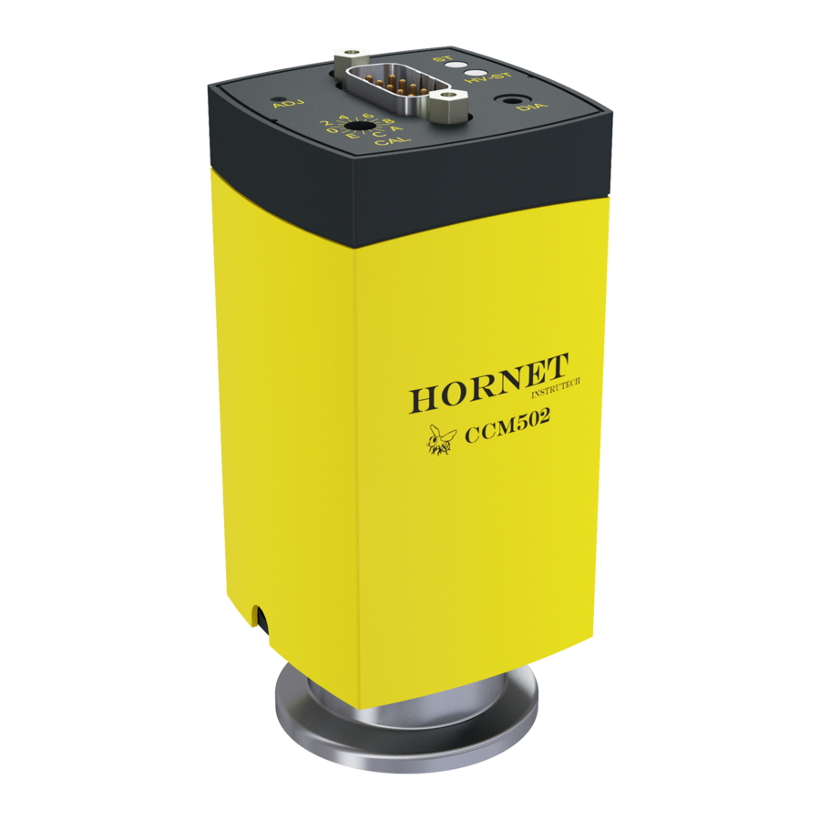
- Page 1 InstruTech® Cold Cathode Ionization Vacuum Gauge CCM502 Module The Hornet™ User Manual InstruTech 1475 S. Fordham St. Longmont, CO 80503 Phone: +1-303-651-0551 Fax: +1-303-678-1754 E-mail info@instrutechinc.com www.instrutechinc.com p/n 002552-100...
- Page 2 In no event will InstruTech be responsible or liable for indirect or consequential damages that result from the use or application of this equipment.
- Page 3 Copyright © 2016 by InstruTech All rights reserved. No part of this work may be reproduced or transmitted in any form or by any means, electronic or mechanical, including photocopying and recording, or by any information storage or retrieval system, except as may be expressly permitted in writing by InstruTech.
-
Page 4: Table Of Contents
Connectors pin-out........................... 12 Setup and Operation ............................13 Applying power ............................13 Overpressure shut down .......................... 13 Activating the sensor ..........................13 Status Indication ............................14 Sensor activation delay ..........................14 Using the gauge with different gases ....................... 15 InstruTech Page 1... - Page 5 Removing the gauge from service ......................18 7.4.1 Inspecting the sensor ........................19 7.4.2 Replacing the ionization chamber and sensor activation aid ............20 7.4.3 Replacing the measuring chamber ....................22 Troubleshooting ............................23 Factory Service and Support ..........................24 Warranty ................................24 InstruTech Page 2...
-
Page 6: Introduction / General Information
N /air, etc. The InstruTech® CCM502 Hornet™ module provides the basic signal conditioning required to turn a cold cathode vacuum gauge into a complete measuring instrument. The module provides a log-linear analog output for the measured pressure and requires a digital input to activate the sensor. -
Page 7: Dimensions
(SELV) and limited power source (LPS), Class 2. The connection to the gauge has to be fused. Dimensions in. (mm) Fitting dimension A NW25KF 0.59 in. (15 mm) NW40KF 0.67 in. (17 mm) 2 3/4 in. Conflat® 0.91 in. (23 mm InstruTech Page 4... -
Page 8: Part Numbers
24 Vdc @ 750 mA (18 W) Connector: 9-pin D-sub female to mate with and power the CCM502 module Cable length: 6 ft. (2 m) Note: 9-pin D-sub connector backshell can be opened to enable connections to signals and relays InstruTech Page 5... -
Page 9: Important Safety Information
CCM502 Hornet 2 Important Safety Information InstruTech has designed and tested this product to provide safe and reliable service, provided it is installed and operated within the strict safety guidelines provided in this manual. Please read and follow all warnings and instructions. -
Page 10: Safety Precautions - Service And Operation
Do not use if the unit has been dropped or the enclosure has been damaged. Contact InstruTech for return authorization and instructions for returning the product to InstruTech for evaluation. -
Page 11: Electrical Conditions
In cases where an equipment failure could cause a hazardous condition, always implement fail-safe system operation. For example, use a pressure relief device in an automatic backfill operation where a malfunction could result in high internal pressures if the pressure relief device was not installed on the chamber. InstruTech Page 8... -
Page 12: Gas Dependency
WARNING! The measurement value is gas dependent. The pressure reading applies to dry air, O , CO and . For other gases, the measurements have to be corrected. Refer to section 5 titled “Using the gauge with different gases” for a more details. InstruTech Page 9... -
Page 13: Installation
Remove the protective lid and install the product to the vacuum system following manufacturer’s recommendations for different flanges and fittings. Keep the protective lid for future maintenance. Seal with centering ring Protective lid Seal with centering ring and filter Clamp InstruTech Page 10... -
Page 14: Electrical Installation
• Use an overall metal braided shielded cable. The connector must have a metal case. • Connect the supply common with protective ground directly at the power. • Use differential measurement input (signal common and supply common conducted separately). • Potential difference between supply common and housing ≤16 V (overvoltage protection). InstruTech Page 11... -
Page 15: Connector
Sensor on/off status is determined by open collector transistor (ground emitter) rated at 30 V max. V , 100 mA max. I Transistor off = Sensor off, Transistor on = Sensor on Wiring Diagram * Applying continuous ground activates the cold cathode sensor. InstruTech Page 12... -
Page 16: Setup And Operation
Connect power to the CCM502 using the designated pins 4 and 2 of the 9-pin D-sub connector. Alternatively, you can power the device by connecting InstruTech’s PS501-A power supply to the connector. Read this user manual in its entirety before activating the sensor. Refer to section 4.3... -
Page 17: Status Indication
… 7.60 × 10 Torr < 1 second 7.6 × 10 … 7.6 × 10 Torr < 20 seconds 3.75 × 10 … 7.6 × 10 Torr < 2 minutes < 3.75 × 10 Torr < 20 minutes InstruTech Page 14... -
Page 18: Using The Gauge With Different Gases
= 6 X 10 Torr true pressure of argon gas eff = A mixture of gases and vapors is often involved. In this case, accurate determination is only possible with a partial pressure measurement instrument, e.g. a quadrupole mass spectrometer. InstruTech Page 15... -
Page 19: Analog Output
Pressure is plotted on the X-axis with a log scale; the output signal is plotted on the Y-axis on a linear scale. + 10 VDC See the conditions described above which cause the output to switch to + 10VDC. InstruTech Page 16... -
Page 20: Service
• Replace the measuring chamber (spare sensor) InstruTech assumes no liability and the warranty becomes null and void if any repair work other than replacing the sensor activation (ignition) aid, measuring or ionization chambers is carried out by the end-user or third parties. -
Page 21: Removing The Gauge From Service
Always use clean, lint free gloves as well as clean tools when working with this product. 1) Vent the vacuum system and turn off power to the gauge. 2) Unplug the cable and remove the gauge from the chamber. 3) Re-install the protective lid. Seal with centering ring Protective lid Clamp InstruTech Page 18... -
Page 22: Inspecting The Sensor
Possible cause between pins 5 + measuring Contamination, ∞ <<∞ chamber short circuit cold cathode sensor Measuring chamber Replace measuring chamber if defective. It is recommend to perform a leak test (leak rate <1×10 mbar l/s). InstruTech Page 19... -
Page 23: Replacing The Ionization Chamber And Sensor Activation Aid
CAUTION! concentrically. Do not bend the anode. • Insert the new ignition aid into the mounting tool with the jagged side downwards … … and slide it onto the anode until the stop position is reached. InstruTech Page 20... - Page 24 Carefully slide the measuring chamber (3) (clean or new) into the electronics unit (5) until the mechanical stop is reached. Pins aligned straight. Fasten the measuring chamber (3) by means of the hexagon socket set screw (4). InstruTech Page 21...
-
Page 25: Replacing The Measuring Chamber
WARNING! Helium may cause electric arcing with detrimental effects on the electronics of the product. Before performing any leak tests disconnect power and remove the electronics unit. InstruTech Page 22... -
Page 26: Troubleshooting
EEPROM error Switch the gauge off and on again after 5 s Replace the gauge Signal continually at approx. lid solid lid solid Measuring chamber Replace the measuring chamber 3.8 x 10 Torr green green severely contaminated InstruTech Page 23... -
Page 27: Factory Service And Support
(examination of which shall disclose to SELLER's satisfaction that it is defective) returned, to SELLER's plant, properly identified within twenty four (24) months (unless otherwise noted) after the date of shipment from InstruTech Plant. BUYER must obtain the approval of SELLER and a return authorization number prior to shipment. - Page 28 InstruTech® 1475 S. Fordham St. Longmont, CO 80503 Phone +1-303-651-0551 Fax +1-303-678-1754 E-mail info@instrutechinc.com www.instrutechinc.com p/n 002552-100...
Need help?
Do you have a question about the Hornet CCM502 and is the answer not in the manual?
Questions and answers