
Related Manuals for Axia iQx AES67


Summary of Contents for Axia iQx AES67
- Page 1 Axia ® AES67 Console with Integrated Engine Installation & User’s Guide Version 1.0 November, 2018 1490-00203-001 --- USER MANUAL: AXIA IQX TelosAlliance.com...
- Page 2 User Warnings and Cautions The installation and service instructions in this manual are for use by qualified personnel only. To avoid electric shock, do not perform any servicing other than that contained in the operating instructions unless you are qualified to do so. Refer all servicing to qualified personnel This instrument has an autoranging line voltage input.
- Page 3 Updates Axia iQx features and operations are determined largely by software. The Telos Alliance strives to provide the most stable and feature-rich software available. We encourage you to check for software updates from time to time by visiting our website or by contacting us directly.
-
Page 4: We Support You
Eastern Time, Monday through Friday. By Email. Non-emergency technical support is available at Support@TelosAlliance.com. By Web The Axia Web site has a variety of information that may be useful for product selection and support. The URL is https://www.telosalliance.com/Axia SERVICE You must contact Telos Alliance before returning any equipment for factory service. We will need your unit’s serial number, located on the back of the unit. -
Page 5: Table Of Contents
Table of Contents Warnings and Cautions . . . . . . . . . . . . . . . . . . . . . . . . . . . ii We support you…... - Page 6 Remote . . . . . . . . . . . . . . . . . . . . . . . . . . . . . . . . . . 14 Overbridge .
- Page 7 System Configuration Console Config . . . . . . . . . . . . . . . . . . . . . . . . . . . . . . . 53 V-Mixer and V-Mode .
- Page 9 We’re grateful that you have chosen audio tools from Telos® Systems, Omnia® Audio, Axia® Audio, Linear Acoustic®, 25-Seven Systems®, and Minnetonka Audio®. We’re here to help you make your work truly shine.
-
Page 11: Quick Start Guide
Quick Start Guide Quick Start Guide On the underside of the iQx console, find the connections for network, power, and expansion modules. Connect the uplink port (A) to a 1 gigabit ethernet link on your switch. Connect power (B) to either power ports. Connect expansion modules (optional) to the expansion module ports (C ). - Page 12 Quick Start Guide Press and hold the METER button (D) until the Studio display (E) changes to a menu. Rotate the Studio knob (F) to highlight NETWORK, press the knob in to enter. Rotate the knob to highlight IP ADDRESS, press the knob to enter. The display will show the 4 octets of an IP address.
- Page 13 Quick Start Guide If installing expansion modules (optional), select the Console Config link (G). Console 2 and 3 ports are inactive by default, use the drop down (H) to select the correct expansion module that is connected. Use the Fader Order (I) arrows to organize the fader numbers to the physical placement of the expansion modules.
- Page 14 Quick Start Guide In the iQx Control Center navigation in the left column under Profile Manager click “Sources” (P) to view the Sources screen (Q). Press the Create button (R ), while noting the type of source is the default Line Input (review Chapter 3 for details on the options here).
- Page 15 Quick Start Guide With some profiles created, load them to a channel on the console by pressing the knob at the top of any channel, in the channel display, highlight the source by rotating the knob, select the source by pressing the knob. Make sure you have the channel assigned to Program 1 by pressing the PGM1 button at the top and also that the monitor section also has PGM1 selected.
-
Page 17: Introduction To Iqx
Chapter 1 | Introduction to iQx Thank you for choosing Axia® as your choice in AoIP studios. We know there are many options available to you and believe you will be satisfied with your purchase thanks to the ease of setup, technical support, and reliability of the product. This chapter... -
Page 18: Iqx Surface
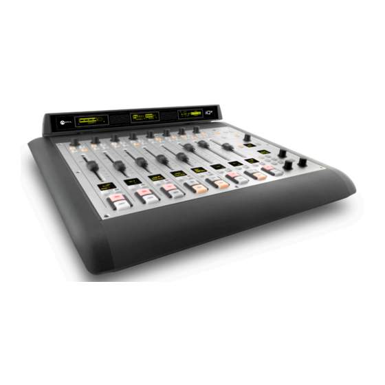
Introduction to iQx Chapter 1 | iQx Surface The main surface is the heart of the iQx system. In addition to the integrated DSP engine, it includes: A - 8 console channels (covered in chapter 2) B - Monitor control section (covered in chapter 2) C - Meter overbridge (covered in chapter 2) D - Dual network ports: These allow for a connection to the network (the port furthest from power) and for connection to a local IO product (the port nearest to the power). -
Page 19: Surface Operation
Surface Operation Chapter 2 | Surface Operation This chapter will cover the physical layout and user operation of the console surface. (For configuration, please refer to later chapters.) Channel Strip The main surface and each expansion module (sidecar) have a set amount of channel strips, either 8 or 6. A - ON/OFF Buttons At the bottom of the channel are the ON and OFF buttons. -
Page 20: C - Channel Display
For example, if the source is owned by another console, the “Used EW” (used elsewhere) message will appear. If the source supports and is using Extra Label feature available in some Axia products, this text will appear under the label. -
Page 21: G - Option Knob
Surface Operation Chapter 2 | G - Option Knob The option knob can be rotated or pressed to trigger system actions. By default, pressing the knob will trigger the display (C ) to show a menu, which can be further navigated by rotating the knob and pressing to select. -
Page 22: Monitor Section
Surface Operation Chapter 2 | Monitor Section The Monitor section gives control to the monitors located in the control room and in an external talk studio, and provides control to an event timer. You’ll also find the console’s meter presentation and clock presentation are accessible here. This is also where you will find Show profiles, a layout configuration for the surface, which the operator can change by accessing the monitor section. -
Page 23: G - Talk To Studio Button
Surface Operation Chapter 2 | G - Talk to Studio Button The button below the Studio knob is used to talk into the Monitor Feed for cueing purposes. Pressing TALK TO STUDIO will take the audio of the Operator profile and feed it directly to the Studio Monitor feed. By Default the source defined as the Operator will be used for this talkback and this source would need to be loaded to a fader. -
Page 24: Remote
Surface Operation Chapter 2 | Remote Many of the important operations that are achieved from the surface can also be controlled remotely from the web browser. A simple static display with controls is offered from the Remote link that allows for simple control. From the page, the Show Profile, Record mode, Source Profiles, Fader Gain, Channel States can be changed, and you can control the monitor section. -
Page 25: Clocks (C)
Surface Operation Chapter 2 | Clocks (C) The third display is split in half to show the time and a count up timer. The clock can be configured to show the day’s date, seconds, or military time (24 hours). Note that AES67 sync comes from PTP and a grandmaster sync source would include real time. -
Page 26: Selectable (Multi-Line) Mode
Surface Operation Chapter 2 | Selectable (Multi-Line) Mode With the Telco expansion sidecar installed, the operator has access to a 6 line selection panel for controlling two phone channels. The key pad (A) should be familiar to anyone who has used a phone. The XFER (transfer) button (B) can function depending on the version of Telos VX and the PBX system. -
Page 27: User Button Option
5 for setup. As for usage, it really depends on how it is set up. There is no predefined button function. If the button is pushed, it will trigger an action at a GPIO port, in channel logic, or within Axia Pathfinder Routing Control. -
Page 29: Audio Configuration
Audio Configuration Chapter 3 | Audio Configuration In the iQx console, we use profiles to categorize audio that is already in the network and to define the behavior of the console. The iQx uses Source Profiles to define the audio inputs to the console. The use of Show Profiles is to define the layout of the console and in some cases how the console is to be used. -
Page 30: Source Profile Options
Audio Configuration Chapter 3 | The options to select are: Line Input – Used for any general audio source. A GPIO logic port can be used to provide machine start/stop pulses if ♦ desired. Refer to GPIO tables (chapter 4) for assigned logic. Computer Player –... - Page 31 Audio Configuration Chapter 3 | Source Input This setting defines the AoIP source or internal DSP source. Which option you select dictates the input into the Primary Source field. The option are: Livewire – the original AoIP. ♦ Livewire Backfeed – the backfeed streams produced by consoles can be ingested if your application requires it. ♦...
- Page 32 Audio Configuration Chapter 3 | Signal Mode for Record Bus The Record mix (bus) is a special variation of PGM 4 that is post-fader but pre ON/OFF (default). This field defines how the source will feed the mix. The options are: Stereo –...
- Page 33 Audio Configuration Chapter 3 | Compressor ♦ Threshold, down to -30 dB, at which the Compressor activates to attenuate input signals above this value. ◊ Ratio, the aggressiveness of the compressor, up to 16:1. A zero change ratio would be 1 to 1 (1:1). Most ◊...
- Page 34 Audio Configuration Chapter 3 | Preview Mode Permits choosing whether Preview acts in CUE (pre-fader) or SOLO (post-fader) mode. Preview Switching Check all options that apply to the prefered workflow. Channel ON turns Preview OFF ♦ Preview ON turns Channel OFF ♦...
-
Page 35: Show Profiles
Audio Configuration Chapter 3 | Feed to Source Sim Gain (Phone, Codec, Microphone, and Studio Feed Type) Talkback is sent over dimmed backfeed audio (default of -10dB). If you want a hard interruption (Talkback interrupts Program audio), set the value to -inf. Adjustment to the attenuation amount is in the range is 0dB to -30dB. Hybrid for Telos Phone (Phone Type) This field helps define the Telos VX configuration to interface with. -
Page 36: Editing Show Profiles
Audio Configuration Chapter 3 | Editing Show profiles Show Name A seven character friendly name for the operators to ID their desired profile. Fader Channels A table that represents the amount of fader channels enabled in the system. Each row represents a chanel and the options are to select a source profile (A) that loads when the show is called. - Page 37 Audio Configuration Chapter 3 | Phone Connection Interfacing with a VX system is configured in the Phone Connection section. Having each show profile with the option to connect to either a different server or different studio adds flexibility. The Phone Server IP field is for the IP address of the Telos VX product. The Studio Name field is a Studio Configuration defined in the VX.
- Page 38 Audio Configuration Chapter 3 | Preview In - define if the Preview mix is mixed into other monitor points. ♦ Preview Mode - define if Preview feeds the operator headphone in stereo or mono mix to one channel. ♦ Logic Port - define the Livewire channel number for the monitor logic. This value would be applied to a GPIO port. ♦...
-
Page 39: Capture A Profile
Disabled - effectively the button does nothing and these is no Record mode ♦ Enabled - toggle the historical Axia record mode. When in record mode, the monitor section will change to the ♦ specialized Record mix, muting the CR monitors, and trigger GPIO. Refer to GPIO section for GPIO-specific information. -
Page 40: Audio Outputs
Audio Configuration Chapter 3 | Audio Outputs The outputs page is accessed via the Outputs link under IO Manager. The page provides 32 outputs that can each be defined to the facility needs. The default setting is for unused outputs to be reserved for Auto Backfeed. When a source is loaded that calls for a backfeed, one of the outputs from the pool of Auto Backfeed will be assigned (and configured) as the backfeed. - Page 41 Audio Configuration Chapter 3 | Talk to External is audio content from the designated Talk source when the CR Monitor logic of TALK TO ♦ EXTERNAL is triggered (refer to the GPIO section). As mentioned in the Show Profile section above, the designated TALK source is either the Operator Microphone assigned to a channel or the show profile EXT TALK designation.
-
Page 43: Gpio
Axia, from its beginning, has made the process of configuring GPIO as plug-and-play as possible. The strategy to achieve this is via defined behavior through profiles. An audio source is defined through the Source Profile (chapter 3) and this profile creates GPIO behavior. - Page 44 Chapter 4 | The following tables show pin numbers as they would appear on an Axia xNode for install support. The Axia GPIO ports are 15 pin. Some of the pins are not reflected in the tables because the pins of power are common pins as shown below: Pin 7: GPO common pin.
-
Page 45: Line Profile Gpio Table
GPIO Chapter 4 | Line Profile GPIO Table Inputs (GPI) Name Notes GPI 1 ON Command Pin 11 Momentary turns ON the console channel, triggers START pulse GPI 2 OFF Command Pin 12 Momentary turns OFF the console channel, triggers STOP pulse GPI 3 PREVIEW Command... -
Page 46: Computer Player Profile Gpio Table
GPIO Chapter 4 | Computer Player Profile GPIO Table Inputs (GPI) Name Notes GPI 1 ON Command Pin 11 Momentary turns ON the console channel, triggers START pulse GPI 2 OFF Command Pin 12 Momentary turns OFF the console channel, triggers STOP pulse GPI 3 PREVIEW Command... -
Page 47: Phone Profile Gpio Table
GPIO Chapter 4 | Phone Profile GPIO Table GPI (Inputs) Name Notes GPI 1 ON Command Pin 11 Momentary turns ON the console channel, triggers START pulse if ON is configured to answer Hybrid GPI 2 OFF Command Pin 12 Momentary turns OFF the console channel, triggers STOP pulse if ON is configured to answer Hybrid GPI 3... -
Page 48: Codec Profile Gpio Table
GPIO Chapter 4 | Codec Profile GPIO Table GPI (Inputs) Name Notes GPI 1 ON Command Pin 11 Momentary turns ON the console channel GPI 2 OFF Command Pin 12 Momentary turns OFF the console channel GPI 3 TALK TO CR Command Pin 13 Active = Routes channel audio to Preview and mutes channel... -
Page 49: Operator Microphone Profile Gpio Table
GPIO Chapter 4 | Operator Microphone Profile GPIO Table GPI (Inputs) Name Notes GPI 1 ON Command Pin 11 Momentary turns ON the console channel GPI 2 OFF Command Pin 12 Momentary turns OFF the console channel GPI 3 TALK TO STUDIO Command Pin 13 Active = TALK TO STUDIO Will MUTE channel... -
Page 50: Cr Producer Microphone Profile Gpio Table
GPIO Chapter 4 | CR Producer Microphone Profile GPIO Table GPI (Inputs) Name Notes GPI 1 ON Command Pin 11 Momentary turns ON the console channel GPI 2 OFF Command Pin 12 Momentary turns OFF the console channel GPI 3 TALK TO STUDIO Command Pin 13 Active = TALK TO STUDIO... -
Page 51: Cr Guest Microphone Profile Gpio Table
GPIO Chapter 4 | CR Guest Microphone Profile GPIO Table GPI (Inputs) Name Notes GPI 1 ON Command Pin 11 Momentary turns ON the console channel GPI 2 OFF Command Pin 12 Momentary turns OFF the console channel GPI 3 TALK TO CR Command Pin 13 Active = TALK TO CR (Preview channel) -
Page 52: Studio Guest Microphone Profile Gpio Table
GPIO Chapter 4 | Studio Guest Microphone Profile GPIO Table GPI (Inputs) Name Notes GPI 1 ON Command Pin 11 Momentary turns ON the console channel GPI 2 OFF Command Pin 12 Momentary turns OFF the console channel GPI 3 TALK TO CR Command Pin 13 Active = TALK TO CR (Preview channel) -
Page 53: External Microphone Profile Gpio Table
GPIO Chapter 4 | External Microphone Profile GPIO Table GPI (Inputs) Name Notes GPI 1 ON Command Pin 11 Momentary turns ON the console channel GPI 2 OFF Command Pin 12 Momentary turns OFF the console channel GPI 3 TALK TO CR Command Pin 13 Active = TALK TO CR (Preview channel) Will MUTE channel... -
Page 54: Studio Feed Profile Gpio Table
GPIO Chapter 4 | Studio Feed Profile GPIO Table GPI (Inputs) Name Notes GPI 1 ON Command Pin 11 Momentary turns ON the console channel GPI 2 OFF Command Pin 12 Momentary turns OFF the console channel GPI 3 TALK TO CR Command Pin 13 Active = TALK TO CR (Preview channel) Will MUTE channel... -
Page 55: Control Room Profile Gpio Table
GPIO Chapter 4 | Control Room Profile GPIO Table GPI (Inputs) Name Notes GPI 1 MUTE CR Command Pin 11 Mutes Preview and Monitors while active GPI 2 DIM Command Pin 12 Dims Monitors while active GPI 3 EXT PREVIEW Command Pin 13 Routes External Preview defined in show to Preview GPI 4... -
Page 56: Studio Profile Gpio Table
GPIO Chapter 4 | Studio Profile GPIO Table GPI (Inputs) Name Notes GPI 1 MUTE Studio Command Pin 11 Mutes Monitors while active GPI 2 DIM Command Pin 12 Dims Monitors while active GPI 3 RESET Timer Command Pin 13 Starts or resets Timer on console GPI 4 Not used... -
Page 57: Film Cap Buttons Profile Gpio Table
GPIO Chapter 4 | Film Cap buttons Profile GPIO Table GPI (Inputs) Name Notes GPI 1 BUTTON 1 lamp Pin 11 Illuminates the button while active (top button) GPI 2 BUTTON 2 lamp Pin 12 Illuminates the button while active GPI 3 BUTTON 3 lamp Pin 13... -
Page 58: Record (Enable) Mode Profile Gpio Table
GPIO Chapter 4 | Record (Enable) Mode Profile GPIO Table GPI (Inputs) Name Notes GPI 1 Not used Pin 11 GPI 2 Not used Pin 12 GPI 3 Not used Pin 13 GPI 4 Not used Pin 14 GPI 5 Not used Pin 15 GPO (Outputs) -
Page 59: External Timer Control Profile Gpio Table
GPIO Chapter 4 | External Timer Control Profile GPIO Table GPI (Inputs) Name Notes GPI 1 START command Pin 11 Momentary will start the timer GPI 2 STOP command Pin 12 Momentary will stop the timer GPI 3 RESET command Pin 13 Momentary will reset the timer GPI 4... -
Page 60: V-Mixer Profile Gpio Table
GPIO Chapter 4 | V-Mixer Profile GPIO Table GPI (Inputs) Name Notes GPI 1 In 1 ON command Pin 11 Normal: Latch to turn ON Toggle: Momentary for ON/OFF GPI 2 In 2 ON command Pin 12 Radio: Last momentary is ON, all others OFF GPI 3 In 3 ON command Pin 13... -
Page 61: Show Profile Profile Gpio Table
GPIO Chapter 4 | Show Profile Profile GPIO Table GPI (Inputs) Name Notes GPI 1 None command Pin 11 Changes to the blank profile GPI 2 Profile A command Pin 12 Change to the A profile GPI 3 Profile B command Pin 13 Change to the B profile GPI 4... -
Page 63: System Configuration
System Configuration Chapter 5 | System Configuration Console Config Beyond the main 8-fader surface with a monitor section, the system can be expanded with sidecars connected to the underside of the main. There are three options of sidecars, 8-Fader expansion, 6-fader expansion with Phone control, and the 6-fader expansion with User buttons. -
Page 64: V-Mixer And V-Mode
System Configuration Chapter 5 | V-Mixer and V-Mode The V-Mixer and V-Mode are small utilities included that help with odd audio needs every studio runs into. The V-Mixer is a 5-input mixer with an ON switch and gain stage for each input. The V-Mixer output goes through a final gain stage. -
Page 65: Backup & Restore
System Configuration Chapter 5 | Backup & Restore All the hard work in setting up profiles and the smaller details are saved in a configuration backup file which can be downloaded from the Backup / Restore link. From the same page, a backup file can be selected and uploaded into the system. A backup is a recommended step after first install and after any major changes to the configurations. -
Page 67: Appendix: Mechanical
Mechanical Appendix A | Appendix: Mechanical... -
Page 69: Appendix: Tear Sheets - Specific Use Case Configurations
Mechanical Appendix A | Appendix: Tear Sheets - Specific Use Case Configurations AES67 input 1. Define a source profile by selecting the Sources link followed by selecting the type of source and the create button. The type of source will only impact muting. The function of GPIO logic or mix minus generation are dependant on Livewire utilization. -
Page 70: On Air Light
Logic port property mentioned above. If the web page provides pin status, you should be able to see the first GPO go active when the mute status of the monitor is active. Most Axia GPIO ports provide continuity from the pin to a common pin. -
Page 71: Phone Setup To Vx
Tear Sheets - Specific Use Case Configurations Appendix B | Phone setup to VX VX defines Studios and Shows within its own configuration. These VX properties are used in the communication between the client (iQx) and the server (VX Engine). The act of the iQx accessing as a client to VX is defined within the iQx Show profile. 1. -
Page 72: Split Recording Of Telephone Calls
Tear Sheets - Specific Use Case Configurations Appendix B | Split recording of telephone calls A common practice is to record phone conversation in a two track recording, giving access to post edit the caller or host audio. Within a Source profile is the Signal mode for Record bus property. -
Page 75: Warranty
Telos Alliance Warranty Telos Alliance Limited Warranty For the latest Telos Alliance warranty, visit: telosalliance.com/warranty. - Page 76 1241 Superior Ave. • Cleveland, Ohio, 44114, USA • +1.216.241.7225 • TelosAlliance.com © 2018 TLS Corp., All Rights Reserved. C18/16067 • P/N: 1490-00203-001 --- USER MANUAL: IQX...
Need help?
Do you have a question about the iQx AES67 and is the answer not in the manual?
Questions and answers