
Related Manuals for Axia iQ


Summary of Contents for Axia iQ
- Page 1 Console System Installation & User’s Guide Manual Rev 1.3.1 — June, 2014 for iQ v1.00 and higher p/n 1490-00067-001...
- Page 2 Ventilation Warning ministere des Communications du Canada.” The Axia QOR.32 requires the free flow of air for adequate cooling. Do not block the ventilation open- CE Conformance Information: ings in the top and rear of the unit. QOR.32 must be...
-
Page 3: Customer Service
Inquiry@AxiaAudio.com Copyright © 2014 by TLS Corporation. Published by Axia Audio. We reserve the right to make improvements or changes in the prod- ucts described in this manual, which may affect the product specifications, or to revise the manual without notice. All rights reserved. -
Page 4: Warranty
Notice Feedback is welcome All versions, claims of compatibility, trademarks, etc. At Axia, we love to hear your feedback. If you find of hardware and software products not made by Axia anything in this manual that you feel needs clarifica-... -
Page 5: Table Of Contents
Live Controls ....iQ Outputs ..... . . 17 A Note From The CEO of Telos. - Page 6 Chapter Six: Advanced Controls ... . 57 iQ Configuration Screens ....57 The iQ Control Center ....
- Page 7 A Note From The Vice President of Axia 2013 marks a banner year for Axia — this year of IP-Audio. Axia consoles are the first and only IP- marks the first decade of the Connected Studio. Audio consoles with a pre-configured network switch built in, to save broadcasters the effort and expense In retrospect, it’s hard to believe it’s been 10 years...
- Page 8 CAT.6, small and light yet sound and data pour forth. What magic is this?. © 2014 Axia Audio - Rev 1.3.1...
-
Page 9: Getting Started
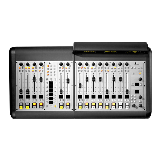
You’ve probably unpacked your boxes and are sitting you’ll likely want to do some in-depth reading about all The iQ Family: (top L-R) iQ 6-Fader, iQ 8-Fader, iQ Phone, iQ Main Frame, (bottom) QOR.32 and QOR Backup PSU © 2014 Axia Audio - Rev 1.3.1... - Page 10 Here’s a brief description of the con- tents of the following chapters: • Chapter 1: iQ Frames and QOR.32 explains con- nections and basic iQ setup. • Chapter 2: iQ Inputs and Outputs explains how to generate Source Profiles and construct backfeeds for selected sources.
-
Page 11: Chapter One: Setup And Connections
Chapter One: Bus accessory panels. A single cable from each Frame will be used to connect it to the QOR.32. Each iQ Frame must have a dedicated Console port. Accessory modules can be daisy-chained from the CANBus Accessory port. Setup and Connections... -
Page 12: Qor.32: Front Panel
Flashing GREEN indicates that sync packets are being The physical arrangement of the frames is complete- received, but that iQ is not yet locked. It is normal for the ly arbitrary. The channel assignments are determined by SYNC indicator to flash for several seconds at startup. If the iQ Main port to which you connect each iQ frame. -
Page 13: Qor.32: Rear Panel
Master. The PSU2 indicator is active only when am QOR Backup is present and when the iQ console is configured NET 1 and NET 2 These indicators provide the status of the two 1000 to incorporate the QOR Backup. -
Page 14: Audio Connections
Audio Connections The QOR.32’s rear panel contains all of the connec- tors used for audio I/O, Ethernet, GPIO, power supply and the connections to your iQ frames. Note that we use RJ-45 connectors for three purposes: • Analog audio inputs and outputs •... -
Page 15: Gpio Connections
Audio Nodes. grams for their DB-15 connectors. iQ Frame and CANBus Connections iQ frames need only a single data / power connection to operate. The QOR.32 includes four power/CANBus connections for use in conjunction with your iQ control surface. -
Page 16: Ip Address Configuration
CANBus port that can be used to distribute data and 48 switch, the Ethernet core switch must have an IP address that is lower than any of your iQ units VDC to CANBus switch modules and accessory panels. or Ethernet edge switches. This function of the... -
Page 17: Console Configuration
You will need to provide your computer with a static IP address that is in the same network as the iQ. For example, if you gave the iQ an Take a break! You’re done with initial set-up. When IP address of 192.168.2.40, a good IP address for your... - Page 18 Crimping the spade lugs, the smell of soldering flux — they’ll be missed. (Not much. ) © 2014 Axia Audio - Rev 1.3.1...
-
Page 19: Chapter Two: Inputs And Outputs
Each Livewire network, direct your web browser to the IP ad- of those inputs has the following parameters: dress of your iQ. When you connect to the iQ, you will • (48 vdc) is individually enabled Phantom Power be prompted for a user name and password. -
Page 20: What's A Profile
Your iQ eliminates these headaches by automatical- have connected to your iQ. We use a concept that we call ly merging audio, logic and program data into a single, Profiles to do this. -
Page 21: Creating A New Source
Most originate with the rear panel input connec- wish to generate a talkback channel for. tors and are used locally in the iQ; some audio sources may be obtained from other devices in your Livewire Once you have selected the source type, click the Create button to proceed to the Source Profile options. -
Page 22: Source Input
Record Mode Equalizer The Record Bus of your iQ is a special variation of Allows you to enable EQ function for the source as © 2014 Axia Audio - Rev 1.3.1... -
Page 23: Panorama Position
CR and Studio monitor and state when the fader is moved up. When in Arm state, headphone buses, or to iQ’s Virtual Mixer. the channel OFF lamp will be illuminated. The chan- nel ON lamp will flash in “wink” mode - a long on- To prevent a source from appearing on these inputs’... -
Page 24: Logic Port
About the PHONE, RECORD and PROGRAM 4 abled, the OFF lamp illuminates when the fader is OFF buses: The iQ PGM-4 mix bus is a special multi- purpose bus that does several things at once to and the Ready command is active on the GPIO. If dis- make life easier for the operator. -
Page 25: Live Controls
OFF and AUTO is selected as the Feed To Source Mode. Congratulations — you’ve created a Source Profiles You can now bring up your new source on an iQ fader. Live Controls This group of radio buttons configures permits “live”... -
Page 26: V-Mixer And V-Mode
Figure 2-7 shows the V-Mixer and V-Mode setup channel of an audio source, or a mono sum. V-Mode lets found in the iQ web pages. At the top of that page, you you accomplish this easily. can see the V-Mixer sub-mixer with its five stereo inputs. -
Page 27: Adding Backfeeds And Gpio
(Figure 2-8). You may also use a figuration Creates mono sum and directs GPIO Node in lieu of iQ’s built-in GPIO ports; just » Mono sum to L: it to the Left channel only. - Page 28 To confirm, choose the key on any of your Options iQ’s fader strips and load your new Phone source. Now press the key just below the fader; you’ll see the Talk status change appear in the display above the channel to indicate that the operator’s mic is talking to this tele-...
-
Page 29: Chapter Three: Console Operation
– or any other With iQ, our goal is to provide you with the most ef- kind – at the touch of a button. ficient human-machine interface possible for fast-paced,... -
Page 30: Gpio
Internet and applied by the station engineer. Axia mating it. The operator never has to worry about sending Support recommends performing backups or making a source back to itself and getting feedback— it just can’t... - Page 31 Figure 3-1: iQ Main - Callouts allows the operator to listen from Preview. PREVIEW Key: to sources before they air. iQ’s bus allows Preview auditioning in full stereo. Individual source profiles A momentary press of any lit key will re- Preview can change Preview to Solo (post-fader) operation.
- Page 32 It is dis- played in medium font. In The fader controls Fader: the previous example, it is the volume of the input source. Figure 3-2: iQ Main - Callouts “[TALKBACK].” There are two modes for the fader: fader-start fader-nor-...
- Page 33 Generally, PGM-1 is the main on-air bus and other Always displays the out- PGM 1-2 Meter: buses are used for produc- put level of the IQ Program 1 tion or other programming bus. requirements. All program outputs are post-fader and PGM 3-4 Meter: post on-off function.
- Page 34 This key allows you to select the Profile Key: ence. The Timer section displays the count-up timer active iQ Show Profile from a group of four pre-con- that may be controlled by fader-start or by the Timer figured profiles. The Studio OLED display tells you controls on the iQ.
-
Page 35: System Settings
External Input. Press Ext 1 or Ext Operation of the iQ 8-Fader frame is identical to that 2 again to exit this Select mode. of the faders on the iQ Main. As described in Chapter 2, fader number designations are determined by the Adjusts the vol- QOR.32 Console port to which the Frame is connected. - Page 36 VoIP PBX and the on-air phone system. iQ was designed with this functionality in mind. As a result, iQ requires a Telos iQ6 or a VX- series phone system to take advantage of this advanced on-console phone integration. iQ’s hy-...
-
Page 37: Iq 6-Fader+User Keys Expansion Frame
Control Room Opera- ers that are found on the iQ Main. Please refer to the tor microphone are temporarily muted, while his mic’s callout descriptions for iQ Main in the previous section. -
Page 38: Studio Microphone Channel
If the Feed-to-Source mode is set to “Auto”, (the most common option - see Chapter 2: iQ Inputs and Outputs for the Studio Microphone Channel Another type of microphone channel is a Studio section entitled “Source Profile Options”), phone callers... -
Page 39: Remote Control
See Chapter 5: Configuring GPIO for detailed infor- mation interfacing to GPIO inputs and outputs. What’s Next Now that you know how what all the controls do, let’s get acquainted with one of iQ’s most powerful func- tions: Show Profiles. © 2014 Axia Audio - Rev 1.3.1... - Page 40 Do digital streams dream of electric DJs? Just Bradbury knows. © 2014 Axia Audio - Rev 1.3.1...
-
Page 41: Chapter Four: Show Profiles
“new” source is the same as the one currently on-air. Capture It! It’s now time to save your iQ configuration as a Show The surface will signal the operator that a source change is pending by blinking the OFF but- Profile. -
Page 42: Show Profile Options
This section has settings for each fader channel. Capture from the menu. iQ allows you to capture up to four Show When this specific Show Profile is loaded, these settings Profiles which are saved as A, B, C and D. You may also will be applied. - Page 43 This is your studio name, as config- Studio Name: ured in the VX system. Monitor Section • This can be the same as your iQ show • You may specify initial vol- Show Name: Volume (-85..0 dB): profile for consistency but it must correspond to a ume settings for the outputs listed below.
-
Page 44: User Interface
» CR Monitor lector displays all sources that have been defined as » CR Headphones iQ sources in the Source Profile manager. » Preview » Studio Monitor What’s External Preview for? “External” re- • This checkbox determines whether fers here to any source not generated inside the Volume Adjust: studio you’re working in. - Page 45 We have mentioned GPIO many times in the preced- ing chapters. Join us in Chapter 5 to learn how to inter- face the logic functions of your iQ console with the real world. © 2014 Axia Audio - Rev 1.3.1...
- Page 46 The ten thousand things How long do they persist? Gates and RCA, gone. © 2014 Axia Audio - Rev 1.3.1...
-
Page 47: Chapter Five: Configuring Gpio
Profile”). This is important, because when that source individually, Axia sends machine controls over the same is assigned to a console fader, iQ uses this Source Profile Ethernet your audio travels on, further reducing infra- selection to tell the GPIO Node what sort of command structure, cost and tedium. -
Page 48: Gpio Operator's Microphone Logic
Input Common Common for all 5 inputs Connect to power supply of source device or to Pin 9 NOT CONNECTED OUTPUT COMMON RETURN ØV (GND) SOURCE +5 V POWER SOURCE GPIO v.”ZA” 4/2009 © 2014 Axia Audio - Rev 1.3.1... -
Page 49: Gpio Control Room Guest Microphone Logic
Source Supply Common for all 5 inputs Connect to power supply of source device or to Pin 9 NOT CONNECTED OUTPUT COMMON RETURN ØV (GND) SOURCE +5 V POWER SOURCE GPIO v.”ZA” 4/2009 © 2014 Axia Audio - Rev 1.3.1... -
Page 50: Gpio Studio (Monitor 2) Guest Microphone Logic
Source Supply Common for all 5 inputs Connect to power supply of source device or to Pin 9 NOT CONNECTED OUTPUT COMMON RETURN ØV (GND) SOURCE +5 V POWER SOURCE GPIO v.”ZA” 4/2009 © 2014 Axia Audio - Rev 1.3.1... -
Page 51: Gpio Producer's Microphone Logic
Source Supply Common for all 5 inputs Connect to power supply of source device or to Pin 9 NOT CONNECTED OUTPUT COMMON RETURN ØV (GND) SOURCE +5 V POWER SOURCE GPIO v.”ZA” 4/2009 © 2014 Axia Audio - Rev 1.3.1... -
Page 52: Gpio Line Input Logic
Source Supply Common for all 5 inputs Connect to power supply of source device or to Pin 9 NOT CONNECTED OUTPUT COMMON RETURN ØV (GND) SOURCE +5 V POWER SOURCE GPIO v.”ZA” 4/2009 © 2014 Axia Audio - Rev 1.3.1... -
Page 53: Gpio Codec Logic
Source Supply Common for all 5 inputs Connect to power supply of source device or to Pin 9 NOT CONNECTED OUTPUT COMMON RETURN ØV (GND) SOURCE +5 V POWER SOURCE GPIO v.”ZA” 4/2009 © 2014 Axia Audio - Rev 1.3.1... -
Page 54: Gpio Telephone Hybrid Logic
Source Supply Common for all 5 inputs Connect to power supply of source device or to Pin 9 NOT CONNECTED OUTPUT COMMON RETURN ØV (GND) SOURCE +5 V POWER SOURCE GPIO v.”ZA” 4/2009 © 2014 Axia Audio - Rev 1.3.1... -
Page 55: Gpio Control Room Monitor Logic
Source Supply Common for all 5 inputs Connect to power supply of source device or to Pin 9 NOT CONNECTED OUTPUT COMMON RETURN ØV (GND) SOURCE +5 V POWER SOURCE GPIO v.”ZA” 4/2009 © 2014 Axia Audio - Rev 1.3.1... -
Page 56: Gpio Studio Monitor Logic
Source Supply Common for all 5 inputs Connect to power supply of source device or to Pin 9 NOT CONNECTED OUTPUT COMMON RETURN ØV (GND) SOURCE +5 V POWER SOURCE GPIO v.”ZA” 4/2009 © 2014 Axia Audio - Rev 1.3.1... -
Page 57: Gpio Computer Playback Device Logic
Source Supply Common for all 5 inputs Connect to power supply of source device or to Pin 9 NOT CONNECTED OUTPUT COMMON RETURN ØV (GND) SOURCE +5 V POWER SOURCE GPIO v.”ZA” 4/2009 © 2014 Axia Audio - Rev 1.3.1... -
Page 58: Gpio Film Legendable User Button Module / Accessory Panel / Rack Panel
Source Supply Common for all 5 inputs Connect to power supply of source device or to Pin 9 NOT CONNECTED OUTPUT COMMON RETURN ØV (GND) SOURCE +5 V POWER SOURCE GPIO v.”ZA” 4/2009 © 2014 Axia Audio - Rev 1.3.1... -
Page 59: Gpio Recording Device Logic
Source Supply Common for all 5 inputs Connect to power supply of source device or to Pin 9 NOT CONNECTED OUTPUT COMMON RETURN ØV (GND) SOURCE +5 V POWER SOURCE GPIO v. 10/2009 © 2014 Axia Audio - Rev 1.3.1... -
Page 60: Assigning Gpio To A Source
Figure 5-3: Pin status indicators showing GPIO port activity Figure 5-1: GPIO Port Assignment © 2014 Axia Audio - Rev 1.3.1... -
Page 61: Connections To Gpio Ports
Figure 5-3. the source is assigned to a iQ channel. Referring to the Hybrid Logic Chart, we can see that Connections to GPIO Ports when the iQ channel is , the indicator represent- ing Output Pin 2 –... -
Page 62: Output Connections
Please note that this section is provided as a “jump- Output Connections start” introduction to Axia GPIO nodes. For a fuller The GPIO port’s outputs are opto-isolated. Current understanding of the GPIO node’s options and require- should be limited 100 mA through each output, with the ments, you may wish to read the GPIO Node User’s... -
Page 63: Configuring And Using Iq User Keys
“under the hood” discussion of iQ Advanced Controls. Configuring and using iQ User Keys The 6 Fader + User Keys iQ expansion module pro- vides two sets of 5 programmable “user keys.” You’ll use the iQ Control Center’s Console Configuration page to configure ports for these keys to use. - Page 64 In the future, all radio equipment will be networked. Oh, wait! © 2014 Axia Audio - Rev 1.3.1...
-
Page 65: Chapter Six: Advanced Controls
Figure 6-1 shows the screen that greets you when ceive data rates expressed in Mbps. you log into your iQ from your Web browser. The main » Debug information menu runs down the left side and gives access to options •... -
Page 66: The Customize Menu
» IP Address: Web Access Password: iQ. We suggest that you have a plan to ensure that is set to “user” and the password is blank. If you all of your Livewire devices are assigned unique, want to add a password, type it in both boxes and IP addresses. -
Page 67: Log, Log History And Log Setup Menus
Log, Log History and Log Setup Menus live in the Eastern Tome zone in the USA, your iQ keeps a detailed log of user actions and other sys- GMT offset will be -5 hours, 0 minutes. If you tem events. Choosing the menu item lets you ex- live in Riga, Latvia, your offset will be +2 hours. -
Page 68: Brightness Control Menu
The Module Manager ing updated. heading displays information Module Manager about the iQ Main Frame as well as all other modules (fader frames) and accessories connected to your CAN- Brightness Control Menu Bus ports. Some of these fields are for diagnostics; below... -
Page 69: Profile Manager Menu
What’s Next iQ is designed to be the perfect standalone IP con- sole. But what if you want to use your iQ as part of a larger Livewire studio network? No problem! Read on as we configure networking options for your iQ. - Page 70 Dark, dark as coal tar it pours out, bitter and strong. That’s Starbucks for you. © 2014 Axia Audio - Rev 1.3.1...
-
Page 71: Chapter Seven: Networking With Iq
When properly configured and connected to other that’s just half the story! Like all Axia broadcast prod- iQ consoles (or, in a large studio facility, to an Ethernet ucts, iQ has networking capabilities as well. “core” switch), this network connection permits you to access the resources of other devices connected to your Axia invented networked audio for broadcast. -
Page 72: Outputs
Outputs that input. If you select Livewire, you are telling the iQ that this source is not associated with a local input but is, instead, a source from elsewhere on your Livewire net- The Output configuration of your iQ has two sec- work. -
Page 73: Gpio
» Any internal generated iQ sources including PGM-1, 2, 3 or 4, Record, CR Monitor, CR To deploy iQ in a network setting, you will intercon- Headphones, Preview, Talk to CR, Talk to Ex- nect the Ethernet switch built into your QOR.32 with ternal, Studio Guest HP, Studio Monitor, Stu- other QOR.32s, or to external Ethernet switches. - Page 74 Mimicking nature, streams combine to form anew many become one. © 2014 Axia Audio - Rev 1.3.1...
-
Page 75: Appendix A: Iq Specifications
Internal Sampling Rate: 48 kHz QOR.32: 7 x 19 x 15 inches (4RU), 15 pounds Output Sample Rate: 48 kHz See the figures that follow for detailed dimensions of iQ A/D Conversions: 24-bit, Delta-Sigma, 256x oversampling frames. D/A Conversions: 24-bit, Delta-Sigma, 256x oversampling Latency <3 ms, mic in to monitor out, including network... -
Page 76: Table Of Inputs And Outputs
Mono mix-minus output feeds the left side of a stereo connection. “Talk to...” function enabled. Feed-to-Source B n Mono Mono mix-minus output feeds the right side of a stereo connection. “Talk to...” function disabled. © 2014 Axia Audio - Rev 1.3.1... - Page 77 Main Frame (8 faders + monitor controls) 4.38 20.45 (111,175) (519,331) 19.01 (482,881) © 2014 Axia Audio - Rev 1.3.1...
- Page 78 Telco expansion frame (6 faders + call controller) 17.25 2.91 (438,051) (73,963) 18.20 (462,376) © 2014 Axia Audio - Rev 1.3.1...
- Page 79 (6 faders + programmable keys) 17.25 2.91 (438,051) (73,989) 18.20 (462,376) © 2014 Axia Audio - Rev 1.3.1...
- Page 80 8-Fader expansion frame 17.25 2.91 (438,051) (73,989) 18.20 (462,376) © 2014 Axia Audio - Rev 1.3.1...
-
Page 81: Appendix B: Iq Block Diagrams
PHONE Σ PROGRAM 4 MODE Σ RECORD STEREO SUM TO LEFT SUM TO RIGHT Σ PHONE TALK TO X Σ TALK TO X Revised: January 2010 Figure B-1 Block Diagram - Operator Microphone © 2014 Axia Audio - Rev 1.3.1... - Page 82 STEREO SUM TO LEFT SUM TO RIGHT Σ PHONE TALK TO X Σ TALK TO X TALK TO CR Σ TALK TO CR Revised: January 2010 Figure B-2 Block Diagram - Guest Microphone © 2014 Axia Audio - Rev 1.3.1...
- Page 83 Σ PROGRAM 4 MODE Σ RECORD STEREO SUM TO LEFT SUM TO RIGHT Σ PHONE JOIN TALK TO X Σ TALK TO X Revised: January 2010 Figure B-3 Block Diagram - Line Source © 2014 Axia Audio - Rev 1.3.1...
- Page 84 TALK TO BOTH PGM 2 MIX PGM 3 PGM 3 MIX PGM 4 PGM 4 MIX PHONE PHONE MIX TALK TO X MIX Figure B-4 Block Diagram - Phone Source Revised: January 2010 © 2014 Axia Audio - Rev 1.3.1...
- Page 85 TALK LEFT ONLY PGM 2 MIX PGM 3 PGM 3 MIX PGM 4 PGM 4 MIX PHONE PHONE MIX TALK TO X MIX Figure B-5 Block Diagram - Codec Source Revised: January 2010 © 2014 Axia Audio - Rev 1.3.1...
- Page 86 VMODE OUTPUT PGM 4 MIX Pass Stereo VMIX Mono sum to left only Mono sum to right only VMIX Combine from left and right Figure B-6 Block Diagram - Master Output Revised: January 2010 © 2014 Axia Audio - Rev 1.3.1...
- Page 87 STUDIO MON OUTPUT DIM LEVEL STUDIO TALENT H/P OUTPUT TALK TO X MIX TALK TO EXTERNAL TALK TO ∑ TALK TO X EXT OUT Figure B-7 Block Diagram - Monitor Output Revised: January 2010 © 2014 Axia Audio - Rev 1.3.1...
- Page 88 The cup steams, sweet scent wafting lightly in the air. Mmmmm... it is Earl Grey. © 2014 Axia Audio - Rev 1.3.1...
-
Page 89: Appendix C: Channel / Ip Worksheets
Appendix C: Channel / IP Worksheets The scalable nature of Axia Livewire audio networks makes it possible to construct systems of any size - from a single room to an entire multi-studio facility. Since Livewire components – Audio Nodes, Elements, StudioEngines, PowerStation, iQ, etc. – are connected with Ethernet, each one requires a unique IP (Internet Protocol) address. - Page 90 Axia IP Address Assignment Worksheet IP Address Device Name Location Notes © 2014 Axia Audio - Rev 1.3.1...
- Page 91 Axia Audio Channel Assignment Worksheet - SOURCES Channel ID Number Device Name Device Location Notes © 2014 Axia Audio - Rev 1.3.1...
- Page 92 Axia Audio Channel Assignment Worksheet - DESTINATIONS Channel ID Number Device Name Device Location Notes © 2014 Axia Audio - Rev 1.3.1...
-
Page 93: Warranty
Avenue, Cleveland, Ohio 44114. Axia Audio at its option will either repair or replace the Product and such action shall be the full extent of Axia Audio’s obligation under this Warranty. After the Product is repaired or replaced, Axia Audio will return it to the party that sent the Product and Axia Audio will pay for the cost of shipping. - Page 94 Axia Audio, a Telos Alliance Company • 1241 Superior Ave. • Cleveland, Ohio, 44114, USA • +1.216.241.7225 • www.AxiaAudio.com...
Need help?
Do you have a question about the iQ and is the answer not in the manual?
Questions and answers