Advertisement
Quick Links
EURO 76
QUICK START GUIDE
INSTALLATION
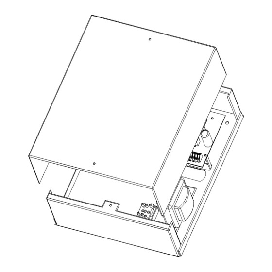
Unscrew and remove the cover of the
EURO 76.
Please note: The above shows the small metal casing. The large casing already has the stand-offs attached out of the box and must be left on to utilise the back tamper correctly.
PCB OVERVIEW
MODEM
INITIAL WIRING
POWER AND BATTERY CONNECTIONS
Ensure wiring is done to the national wiring regulations in the country where the installation is taking place. In the UK, this is BS
7671 Requirements for electrical installations; IET Wiring Regulations (18th edition). If in doubt, consult a local qualified electrician.
Ensure that a readily accessible disconnect device incorporated in the premises installation wiring shall be provided external to the
equipment with a contact separation of at least 3,0mm and connected as closely as possible to the supply. Example: Fused Spur
Unit. When fixing external wires, ensure that means are provided in the installation to prevent the SELV (Safety Electrical Low Voltage)
or signal circuits from coming into contact with live parts of the power supply circuit. Wires shall be fixed near their terminal blocks.
The end of stranded conductor shall not be consolidated by soft soldering at places where the conductor is subjected to contact
pressure. Example: Must not solder ends of wires which are to be secured in detector and control panel terminal connectors. On
completion of wiring use tie-wraps to prevent any loose wires causing a safety hazard (material of cables tie shall be rated at least
HB or better). Cables ties and sleeves shall be separate for power supply cable and SELV (Safety Electrical Low Voltage) wirings.
Size of protective bonding conductors: minimum section 1.5mm². Example: Electrical Earth wire connections.
The EURO 76 printed circuit board is
located to the top right hand side
2-6Ah 7-17Ah
Install the supplied stand-offs if needed
before mounting the metal case to the
wall.
Screw the back metal plate to the wall.
1. Case tamper 'Hold-Off' jumper
2. PGM 1
12v 3A NC/NO relay
3. Speaker connection
Connects 1x 16ohm speaker.
4. External sounder connections
Connects an external sounder.
5. Input connections
8 Fully programmable inputs.
6. Tamper switch
Optional tamper protection for the metal casing.
7. Auxiliary 12V power
12V power supply
8. Inputs or outputs
Inputs 7 and 8 may be programmed as outputs if
unused.
9. Battery connect 'Kick-start' switch
To power-up and program from battery power
(when there is no mains power available).
10. RS485 bus terminals
Connects peripherals.
1 1. Battery connection
For battery back up.
12. Earth connection
Connects the earth.
485 BUS WIRING
Cable Type
4 core alarm cable
6 core alarm cable
(doubling D1 (0v)
and D2 (+12V))
Twisted Pair
The tamper mechanism comes already fitted. Be careful to prevent trapping wires
and replace the enclosure lid, making sure the tamper is operational, then secure
with lids screws.
13. 17V connection
Connects the AC transformer 17V supply.
14. Battery charge capacity jumper
For battery back up.
15. Modem connections
The left connector (labelled 'modem') is for signalling
modules.
16. RS232 connection
This connection is used for an RS232 lead that will
connect to a PC to allow uploading/downloading
of data using the InSite software. It can also support
advanced communications connections such as SIA
with 3
rd
party communicators when not utilising the
app capability.
17. Communication outputs
Connects the supplied communication loom to
enable an additional 9 programmable outputs.
These are low current and would normally be used
when connecting a stand-alone communicator to
the panel.
18. Bell fuse
19. Auxiliary fuse
20. Bus fuse
21. Battery fuse
Wired keypads
x6 max
Internal proximity readers
x5 max
External proximity readers
x5 max
Bus Range
Screened Cable
(m)
300
Use this type of cable
when the wiring of the
485 bus is located
1000
near 230VAC mains
power wiring
1000
Wired zone expanders
x8 max
Output expanders
x2 max
Wired keypads
x6 max
Powered zone expanders
x4 max
Powered output expanders
x2 max
Wiring Format
Star Wiring Range
Daisy Chain Range
50 m
1 km
Advertisement

Subscribe to Our Youtube Channel
Related Manuals for Pyronix EURO 76


Summary of Contents for Pyronix EURO 76
- Page 1 EURO 76 QUICK START GUIDE INSTALLATION Unscrew and remove the cover of the The EURO 76 printed circuit board is Install the supplied stand-offs if needed The tamper mechanism comes already fitted. Be careful to prevent trapping wires EURO 76.
- Page 2 Our office hours are: Monday to Friday 8:00 - 18:30. found by scanning the QR code or navigating to the URL below it. 0333 444 1280 Please note: A pyronix.com installer account is required to access the technicalsupport@pyronix.com www.support.pyronix.com manuals...
Need help?
Do you have a question about the EURO 76 and is the answer not in the manual?
Questions and answers