
Summary of Contents for Simtronics MultiFlame DF-TV7-T
- Page 1 Operating manual Optical Flame Detector MultiFlame DF-TV7 DF-TV7-T Multi-spectrum IR DF-TV7-V Combined UV/IR NOSP16358-03 [04/2016]...
- Page 2 MultiFlame DF-TV7 Page 2 / 56 NOSP16358-03 [04/2016]...
- Page 3 The product may not perform as designed if it is not used and maintained in accordance with the manufacturer’s instructions. The warranties made by Simtronics with respect to the product are voided if the product is not used and maintained as described in this manual.
-
Page 4: Table Of Contents
Product Description .........................6 1.1. Applications ........................6 1.2. DF-TV7-T: multi-spectrum IR ..................7 1.3. DF-TV7-V: combined UV and IR ..................7 1.4. Technical specifications ....................8 1.5. Detection Cartridge ......................9 1.6. Optical self-test function ....................9 1.7. Wireless Configuration Tool.....................9 1.8. Product Code........................10 Technical features ........................11 Performances .........................14 3.1. - Page 5 8.2. List of main faults ......................42 8.3. Replacing the cartridge ....................43 8.4. Replacing the complete detector...................43 Warnings ..........................44 9.1. Safety ..........................44 9.2. Ownership and confidentiality..................44 Warranty ..........................44 Certifications and standards....................45 11.1. Standards ........................45 11.2. Functional Safety ......................45 11.3. Approvals ........................45 11.4.
-
Page 6: Product Description
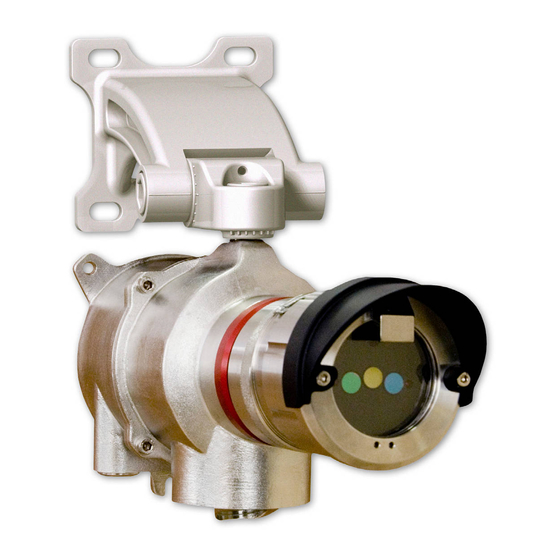
PRODUCT DESCRIPTION MultiFlame DF-TV7-T was designed to detect hydrocarbon fires, while minimizing false alarms. This detector is equipped with an intelligent optical self-test. It is certified and may be installed in SIL2 level system. It can be directly connected to a wide range of traditional or fire controllers and on Programmable Logic Controllers (PLC). -
Page 7: Df-Tv7-T: Multi-Spectrum Ir
1.2. DF-TV7-T: multi-spectrum IR The DF-TV7-T is a multi-spectrum flame detector using three individual infrared wavelengths. The use of three different IR bands and a unique signal processing algorithm allows excellent flame detection performances, while offering a very low rate of false alarms. The detector can be supplied with •... -
Page 8: Technical Specifications
1.4. Technical specifications Each detector is constructed as follows: • A wall-mounted support secured by three screws and including cable gland (M20) (optional). There are 2 standard entries and an optional one. • A stainless steel (316L) explosion-proof housing containing: •... -
Page 9: Detection Cartridge
Information and status of the detector are available via the wireless configuration tool TLU600/610. Configuration and tests are performed using this wireless configuration tool (IrDA protocol). This tool is common for all Simtronics MultiFlame, MultiXplo and MultiTox products. The TLU600/610 provides access to devices which, otherwise, would... -
Page 10: Product Code
1.8. Product Code ξ σ αβ ρ ε µ φ Product codes are created from functional codes: V7-X# Detector type ξ σ α β ρ ε µ φ Télécaptor Network version Families Flame Version BT10 housing Type UVIR2 Detection range σ... -
Page 11: Technical Features
TECHNICAL FEATURES GENERAL Type Optical flame detectors DF-TV6-T Multi-spectrum IR Flame detector DF-TV7-V Combined IR and UV detection. Start-up time 15 secs Self-test Automatic periodic test through the window Calibration Factory set, no field recalibration OUTPUT SIGNAL 4-20mA loop signal Active type (source), max. - Page 12 Protection IP66 RFI/EMI Complies with EN 50130-4 (2011 AMD 2014) PERFORMANCE European EN 54-10/A1 (2005) EXPLOSION PROOF HOUSING Material 316 L stainless steel Weight 5.1 kg ATEX/IECEx II 2 G / Ex d II C T6 Gb -40°C < Ta < + 65°C FONCTIONNAL SAFETY SIL certified according IEC/EN 61508 parties 1 to 3 standard Certification body : LCIE Bureau Véritas...
- Page 13 DIMENSIONS Figure 2 : Dimension drawings MultiFlame DF-TV7 Page 13 / 56 NOSP16358-03 [04/2016]...
-
Page 14: Performances
PERFORMANCES 3.1. Sensitivity 3.1.1. Fire class Classification according to §5.5.3 –NF EN 54-10 (2006), (ethanol and n-heptane fires) DF-TV7-XVA0 ET DF-TV7-XTA0 Sensitivity 100% Time delay Class 2 Class 1 Class 1 Max (20 sec) Class 2 Class 2 Class 1 DF-TV7-XTB0 Class 1 for any combinations of sensitivity and time delay settings. -
Page 15: Field Of View (Cone Of Vision)
3.2. Field of View (Cone of Vision) DF-TV7-XTA0 DF-TV7-XVA0 DF-TV7-XTB0 α : Maximum angle as defined in standard EN 54-10 30° 35° (2006) - § 5.4 Angle at 50% sensitivity Horizontal total 97° 104° (in accordance with FM 3260 Vertical Up / Down 20°... -
Page 16: False Alarm Immunity (Fm 3260)
3.3. False alarm immunity (FM 3260) XTA0 (IR3) Distance XTB0 (IR3) Standard XVA0 (UVIR²) m (ft.) Long range range Modulated / 75 % / 5 sec 100% / 5 sec 100 % / 2 sec Steady (fact. setting) (fact. setting) (fact. -
Page 17: Installation
INSTALLATION The detector must be installed in accordance with its certification and with the standards of the appropriate authority in the country concerned. 4.1. Location The detector should be positioned above the targeted danger zone and at a distance corresponding to the type of fire it have to detect. Be aware of potential radiation sources as these may trigger a false alarm. -
Page 18: Mounting
4.2. Mounting Use the two 7 mm diameter holes and the half slotted hole to secure the support. It is highly recommended to install the support with cable-gland downward in order to avoid water infiltrations. In case of horizontal position, it is advised to make one or two loops with the cable at the entry of the cable-gland. - Page 19 4.2.1.2. Ball pivot bracket – AS048 The detector is supported by a completely adjustable support. The assembly of the bracket with the device is done by a CHC M14 x 24 screw. These one is used to set the lateral orientation.
- Page 20 4.2.3. Sunshade / bad weather protection A sunshade / weather protection (AS056-450) in light and resistant material (UV resistant) is available. Mounted above the detector, it gives an additional protection against sun and bad weather. 4.2.4. Detector cartridge visor The detector is fitted with a short visor for protection of the optical detector window (standard).
-
Page 21: Electric Connection
4.3. Electric Connection Never adjust electric connections when detectors are powered. Maintenance must be undertaken by qualified staff. Observe safety site rules. MultiFlame DF-TV7 is a sensor with standard current output 4-20mA. The connection can be on 3 or 4 wires. The 4 wires configuration allows insulation between the signal and power loops. - Page 22 Figure 4 : Terminal blocks Point JP12 & JP13 Description Relay 2 Relay 2 Relay 1 Relay 1 Point JP11 Description +24VDC power supply +24VDC power supply loop (connected to point 2) 0 V, Connected to point 1 20mA Current loop: entry 20mA Current loop: output 4.3.2.
- Page 23 4.3.4. 3-wires connection (source) Detector JP11 SOURCE Version +24VDC +24VD 20 mA loop Max 700 Ω Shielding to be connected to the enclosure For a standard 3-wires connection, the 20mA current loop must be supplied with 24 V at terminal L+. To proceed, connect the 3 (V +) and 5 (L +) terminals at the terminal block level of the device.
- Page 24 4.3.6. 4-wires connection (isolated power) Fire or control system Detector JP11 4 wires Version +24VDC +24VD 20 mA loop +24VD Typ < 450 Ω Shielding to be connected to the enclosure When using a 4 wires connection, the current loop is provided by the input module or PLC. The loop (L + and L-) is optically isolated from the detector.
- Page 25 4.3.7. Relay Control unit JP12 or JP13 The two relays can be configured normally closed or normally open. If normally open, the relays are opened when they are not powered (power loss). The circuits’ relays are isolated from each other and from other parts of the detector. The two relays can be activated on one or more states of the detector, as shown below: Activated on Relay 1...
- Page 26 4.3.8. Syntel connection In this network version, an electronic board is inserted in the detector body and is used for electric connection. Connecting the ground terminal should be performed thanks to 3-wire shielded cables. The connection of power supply wires (4 on side A and 4 on side B). •...
-
Page 27: Detection Cartridge
4.4. Detection cartridge The cartridge is separated from the detector to enable its replacement. Its dismantling is extremely easy and does not need to touch the rest of the unit. Be careful when plugging or removing the detection cartridge. • Align the centring pin of the cartridge with the corresponding hole in the housing. - Page 28 Default detection mode of the XVA0 (UVIR²) may be changed using DIP switches at the back of the cartridge Switches S1 and S2 are used for the UV/IR detection mode as shown in the table below. The configuration is frozen, and cannot be changed with the TLU. Switches S1 and S2 are not used for the multispectrum sensor cartridges (3IR).
-
Page 29: Commissioning
COMMISSIONING 5.1. Visual inspection Make certain that all the operations of the “Installation” chapter have been achieved correctly. Pay particular attention on installation conformity, check the cables entry, the presence of O- rings, and the connexion of the cartridge. • Check if the detection mode (UV/IR, 3IR) match with the marking 5.2. -
Page 30: Using The Lt15 Test Lamp
5.4. Using the LT15 test lamp The LT15 is a flashing test lamp used for functional test of flame detectors. The emission spectrum of the lamp is between 280 nm (UV) and 5 µm (IR). The emission is pulsed to simulate the typical flickering of flames. LT15 is certified Ex d IIC T6-T5 and suitable for operation in areas with explosion hazard, (zone 1 and 2) in accordance with the EN 60079-0 and EN 60079-1 standards. -
Page 31: Operation
OPERATION 6.1. Environmental conditions • Dust: Dust on the window may limit UV sensitivity • Oil vapour: Oil vapour on the window can reduce UV sensitivity • Water/Ice: The presence of Water or ice can reduce flame detector performances at an infrared level. -
Page 32: Signal Current Loop
6.3. Signal current loop “4-20” “0-22” Status TLU state [mA] [mA] Line fault Configuration fault Hardware fault Sensor fault (Optical self-test) Start-up inhibit Countdown Permanent inhibit. Maintenance inhibit. Previous Previous Default / (“Free mode”) * value / value / (2.0) (3.4) Operation, No faults, No Alarm No detection... -
Page 33: Alarm Indication (Led)
6.6. Wireless communication tool TLU600 All settings and tests of detectors can be done by the wireless communication tool TLU600. This communication tool and its software are compatible with all Simtronics detectors: MultiFlame, MultiTox and MultiXplo. Communication is made via infrared link (IrDA), similar but more efficient than infrared links for computers. - Page 34 6.6.1. Main screen The main screen is composed into several data fields. • C1: Detector name field • C2: Field blank if normal operation; INH- if inhibited • C3: Field blank if normal operation; FLT- if at least one fault has occurred •...
- Page 35 6.6.3. Menu structure • Exploitation : This level enables access to the information and the status of the detectors. It does not allow the configuration operations or write access. • Maintenance : The access to the parameters and other maintenance operations is protected by a password.
-
Page 36: Information Menu [Info]
6.7. Information menu [INFO] The information menu contains all information concerning the identity and settings of the detector. The first screen gives the detector’s reference and its serial number. 6.7.1. [IDEN]tity submenu Presentation of: • detector operation mode (UV/2IR, UV, IR(2IR or 3IR)) •... -
Page 37: Adjustment Menu [Adjt]
6.7.3.4. [INH] screen This screen is dedicated to verify the inhibition mode configuration (frozen or free). If the access level permits it, it is possible to change this setting. 6.8. Adjustment menu [ADJT] This menu presents all the detector settings. All the functionalities, except alarms acknowledgment, request access level 2. - Page 38 OUTPUT SERVICE MODE: • “Standard mode” All pre-alarms, UV or IR detections are disabled. Information is sent in case of confirmed alarm only. • “Expertise mode” Current outputs, relays and LEDs, will be activated on pre-alarm, UV or IR detection (Ref 6.3).
-
Page 39: The Maintenance Menu [Main]
LT15 test menu This menu enables manually tests on detection, using either a test fire or a test lamp (Type LT 15 SIMTRONICS). In this mode, “false alarms rejection” algorithms are by-passed, to make a simulated alarm easier to achieve. -
Page 40: Hart Communication
C, in HART configuration (H): DF-TV7-****-**H-**-***-*-C-* SIMTRONICS devices under HART protocol enable the use of all the functions available with the TLU600 via the HART terminal You will find the description of the commands in a separate document... -
Page 41: Maintenance
MAINTENANCE The interventions described in this chapter must be performed by competent and qualified staff. Device performances may be affected if the present instructions are not respected. Cartridge unplug or device opening imperatively require power to be OFF. 8.1. Periodic maintenance We recommend, at least, a biannual check. -
Page 42: List Of Main Faults
8.2. List of main faults In addition of the current loop faults, other information are available from the wireless communication tool TLU600/610 (refer to § 6.6). If the detector does not work properly, the following table can help you to determine the causes and effects of different possible troubles. -
Page 43: Replacing The Cartridge
8.3. Replacing the cartridge Follow the instruction in §4.4. 8.4. Replacing the complete detector If the operator needs to replace the complete detector, the easiest way is to take off the main housing from the base of the detector (for more details, refer to § 4.2.2). As the base of the detector remains in place, cable glands do not need to be dismantled. -
Page 44: Warnings
The SIMTRONICS warranty shall not apply to faults resulting either, from materials supplied by the Purchaser, from design imposed by the Purchaser, from servicing or maintenance carried out on SIMTRONICS equipment by a third party not explicitly authorized, or from the use of unsuitable storage conditions. -
Page 45: Certifications And Standards
ATEX LCIE 13 ATEX 3025X IECEx IECEx LCIE 13.0022X 11.4. CE-RPC 0333 CPR-075534 / CPR-075535 SIMTRONICS SAS.. .792, Av. de la Fleuride | BP 11061, 13781 Aubagne Cedex, France EN 54-10 : détecteur de flamme – détecteurs ponctuels DF-ξV7-XTσ0-0αβ-0ρ-00ε-µ-φ-0 (DF-TV7-T) (2015) DF-ξV7-XVA0-0αβ-0ρ-00ε-µ-φ-0... - Page 46 11.5.1. ATEX / IECEx versions The MultiFlame identification labels are located on the main detector housing in accordance with the ATEX directive 2014/34/UE and “règlement Produits de Constructions” (UE, n°305/2011) - Manufacturer: SIMTRONICS - Model: DF-TV7… - Serial no.: S/N: xxxxxxxxx...
-
Page 47: Accessories And Spare Parts
ACCESSORIES AND SPARE PARTS 12.1. Accessories Accessories Description References Wireless hand held terminal for configuration and maintenance. TLU610 Remote control unit HART : Avalaible for adjustments and TLU700 maintenance Test lamp LT15 Adapter plate from the former generation of detectors (BT05-BT606) AS0049 to the new one (BT10 : DG, DGi) Multi-position wall mount bracket... -
Page 48: Spare Parts
Sensor cartridge visor, long type, vertical angle restriction. AS041 O-ring. kit for housing and sensor cartridge. 4000284 12.2. Spare parts Spare parts Ordering code Sensor 3IR Standard range Aluminium, DM-SV6-XTA0-0A0-00 Sensor 3IR Standard range SS316 DM-SV6-XTA0-0X0-00 Sensor 3IR Long range Aluminium DM-SV6-XTB0-0A0-00 Sensor 3IR Long range SS316 DM-SV6-XTB0-0X0-00... -
Page 49: Conformity Certificate
CONFORMITY CERTIFICATE MultiFlame DF-TV7 Page 49 / 56 NOSP16358-03 [04/2016]... - Page 50 MultiFlame DF-TV7 Page 50 / 56 NOSP16358-03 [04/2016]...
- Page 51 MultiFlame DF-TV7 Page 51 / 56 NOSP16358-03 [04/2016]...
- Page 52 With the following correspondences: ξ σ α β ρ ε µ φ Télécapteur Capteur réseau / Network version Famille / Families Flamme / Flame Génération BT606 Boitier / housing BT10 Boitier / housing Type Flamme UVIR² Portée de détection σ Portée standard / Standard range Longue Portée (Version XT uniquement) / Long range (only XT versions) Type...
-
Page 53: Contact Details
CONTACT DETAILS You will find an updated list of distributors on our web site: https://gasdetection.3m.com Email address for general enquiries: contact@simtronics.fr Simtronics SAS 792, av de la Fleuride BP 11016, 13781 AUBAGNE CEDEX – France Tel: +33 (0) 442 180 600 Simtronics AS Kabelgaten 8, Økern Næringspark... - Page 54 MultiFlame DF-TV7 Page 54 / 56 NOSP16358-03 [04/2016]...
- Page 55 MultiFlame DF-TV7 Page 55 / 56 NOSP16358-03 [04/2016]...
Need help?
Do you have a question about the MultiFlame DF-TV7-T and is the answer not in the manual?
Questions and answers