Table of Contents
Advertisement
Quick Links
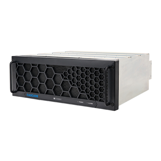
CASCADE SYSTEM
MODULES
OPERATION GUIDE
© 2018 Codan Limited.
No part of this guide may be reproduced, transcribed, translated into any
language or transmitted in any form whatsoever without the prior written
consent of Codan Limited.
CODAN™, NGT™, Easitalk™, CIB™ and CALM™ are trademarks of
Codan Limited. Other brand, product, and company names mentioned
in this document are trademarks or registered trademarks of their
respective holders.
The English version takes precedence over any translated versions.
Document Number:
OG-CASC-SYS-MOD
Revision:
1-0-1P
Revision Date:
May 2018
Security Classification:
PUBLIC
Codan Radio Communications
Victoria, BC
PRINTED IN CANADA
Advertisement
Table of Contents

Related Manuals for Codan Cascade


Summary of Contents for Codan Cascade
- Page 1 Codan Limited. CODAN™, NGT™, Easitalk™, CIB™ and CALM™ are trademarks of Codan Limited. Other brand, product, and company names mentioned in this document are trademarks or registered trademarks of their respective holders.
- Page 2 NOTE The user’s authority to operate this equipment could be revoked through any changes or modifications not expressly approved by Codan Limited. The design of this equipment is subject to change due to continuous development. This equipment may incorporate minor changes in detail from the information contained in this manual.
- Page 3 RF exposure limits. In accordance with KDB 447198 , FCC 47 CFR § 1.1307 (b) and RSS-102 Issue 5 Sect 2.5, the Codan Radio Communications transmitter manufactured in Canada is categorically excluded from routine evaluation or preparing an EA for RF emissions and this exclusion is sufficient basis for assuming compliance with FCC/IC MPE limits.
- Page 4 • For the Band 152 to 174MHz with 6dBi Gain Antenna: d (safe distance) = 4.0 m • For the Band 152 to 174MHz with 10dBi Gain Antenna: d (safe distance) = 6.5 m Cascade System Modules Operation Guide OG-CASC-SYS-MOD-1-0-0P...
- Page 5 RF Maximum Exposure (MPE) Permissible Exhibit Requirements for Installations in Canada No antenna is supplied with this unit. Some suggested antennas are: Manufacturer: Sinclair Model: SC225 Gain: 0 dBd (2.15 dBi) Manufacturer: Sinclair Model: SC233 Gain: 3 dBd (5.15 dBi) Manufacturer: Sinclair Model: SD114...
- Page 6 This Page Intentionally Left Blank Cascade System Modules Operation Guide OG-CASC-SYS-MOD-1-0-0P...
-
Page 7: Table Of Contents
Subrack and Front Panel Safety .............. Regulatory Information ............System Setup ............... Unpack the Subrack ................. Module Configurations ................Cascade Web GUI ................... Cascade Theory of Operation ..........Cascade Power Supply ............Introduction ....................Installation ....................Power Connections .................. Theory of Operation ................. - Page 8 This Page Intentionally Left Blank Cascade System Modules Operation Guide OG-CASC-SYS-MOD-1-0-0P...
-
Page 9: General Information
From a transmitting point of view, CASCADE offers up to two 125-watt power amplifier / transceiver pairs capable of not only P25 Phase I, but also LSM and P25 Phase II. -
Page 10: Base Station / Repeater Specifications
*N/A (≥ 45 dB Analog) Carrier Frequency Stability: ≤ ± 0.5 ppm Audio Distortion (Analog): *N/A (≤ 2%) VSWR Protection: Any (with fold-back) Emission Designators: 8K10F1D, 8K10F1E, 8K10F1W, 8K10F7W, 8K70D1D, 8K70D1E, 8K70D1W, 8K70D7W,9K80D7D, 9K80D7E, 9K80D7W, 11K0F3E Cascade System Modules Operation Guide OG-CASC-SYS-MOD-1-0-0P... - Page 11 20.1 kg / 44.3 lbs [1 channel] 25.9 kg / 57.1 lbs [2 channel] * CASCADE is not equipped with an analog audio input or output. Values noted are typical. Equipment descriptions and specifications are subject to change without notice or obligation.
- Page 12 This Page Intentionally Left Blank Cascade System Modules Operation Guide OG-CASC-SYS-MOD-1-0-0P...
-
Page 13: Safety Information
STOP SIGN When this symbol is shown, DO NOT continue until the safety items identified have been noted and addressed. Ignoring this reminder violates Codan standards of design for the product and will most likely result in severe personal injury or equipment damage. - Page 14 Transmitter. Always follow RF Safety Guidelines. • Exploding Hazard – DO NOT operate the CASCADE equipment if flammable gas or gas fumes are present. • RF Burn Hazard – DO NOT touch the output connector in an open circuit condition while transmitting.
-
Page 15: Subrack And Front Panel Safety
An unqualified user should not remove the front panel as no access is required to this area for any routine operation of the system • The CASCADE subrack and modules should be well ventilated and free from high humidity and excess dust and dirt Front Panel Installed – User Access... - Page 16 This Page Intentionally Left Blank Cascade System Modules Operation Guide OG-CASC-SYS-MOD-1-0-0P...
-
Page 17: Regulatory Information
FCC Title 47 – Part 90 • ANSI C63.4-2014 • FCC Regulation §15.19 • IC RSS-GEN, Sec 8.3 • FCC Regulation §15.105 • IC RSS-102 • ICES-003 • RSS-119 Issue 12 • IC RSS-GEN, Sec 8.4 Cascade System Modules Operation Guide OG-CASC-SYS-MOD-1-0-0P... - Page 18 This Page Intentionally Left Blank Cascade System Modules Operation Guide OG-CASC-SYS-MOD-1-0-0P...
-
Page 19: System Setup
U N PA C K TH E SU B R AC K The CASCADE subrack ships from the factory with the modules installed, based on specific customer configurations. Unpacking procedures require two people (skilled in material handling procedures) to unpack and move the filled subrack. -
Page 20: Module Configurations
FIGURE 1: Complete CASCADE System PA #1 Blanking Power PA #2 Transceiver #2 Transceiver #1 Panel Supply FIGURE 2: CASCADE System – Front View Two Channels Option Power PA #1 Blanking Transceiver #1 PA #2 Supply Panel Transceiver #2 FIGURE 3: CASCADE System – Rear View Two Channels Option... -
Page 21: Cascade Web Gui
System Setup C A S C A D E W E B G U I CASCADE Web GUI is an innovative user interface for the CASCADE system. The GUI has many unique features including: • Full remote access to the Cascade system – no need be preset at the radio site •... - Page 22 This Page Intentionally Left Blank Cascade System Modules Operation Guide OG-CASC-SYS-MOD-1-0-0P...
-
Page 23: Cascade Theory Of Operation
CASCADE THEORY OF OPERATION The CASCADE product is capable of acting as an RF repeater or base station with up to two “Simultaneous Receive Channels” and up to two 125W “Simultaneous Transmit Channels”. The CASCADE product is comprised of the following: •... - Page 24 Cascade Theory of Operation The CASCADE system requires adequate ventilation and ALL vents must be kept clear. The cooling fans will only work when the front panel is properly in place. Cooling airflow moves from the front of the unit to the rear of the subrack so the airflow must not be restricted in any way.
-
Page 25: Cascade Power Supply
94.5%. It delivers up to 2x16.7A output current with 48V output voltage and is capable of operating from -30°C to 60°C. See Figure 5 for images of the CASCADE power supply. The power supply is designed to provide sufficient power for a full CASCADE subrack containing two transceivers, two 125W power amplifiers, three fans and an option slot. -
Page 26: Installation
Cascade Power Supply I N S TALL AT ION The PSU slides in the 5th slot from the left of the CASCADE subrack (see Figure 6). The PSU is fastened with four Phillips screws in the front. FIGURE 6: PSU Installed in Subrack... - Page 27 Front Interface Board (FIB) using the appropriate cable. The last connector on the front bottom is used to communicate with the other CASCADE components The connector uses a ribbon cable and is connected to the FIB in the connector (J5).
-
Page 28: Theory Of Operation
48V. Mounted on the mainboard (DC-DC -48V to 48V Isolated PSU) these bricks are designed for telecommunication purposes and provide the isolation required for CASCADE operation. An auxiliary board (-48V to 13.8V Isolated AUX) is also attached to the mainboard providing a 13.8V output voltage for external use. - Page 29 The power supply’s logic is only used to report its state, including: voltages, currents and temperature to the other components of the CASCADE. The microcontroller receives input from different sections of the PSU and can activate LED lights in the front of the unit and transmit this information via the FIB.
- Page 30 Internal. Foldback, then hiccup past 17.6A In U2 +48V_R Internal. Foldback, then hiccup past 17.6A In U2 Refer to the PSU block diagram in the CASCADE Power Supply section for details. -48V to 13.8V Isolated AUX PSU Input Fuse Type...
-
Page 31: Cascade Transceiver
CASCADE TRANSCEIVER I N T R O D UC T ION The CASCADE Transceiver (TRx) is a full duplex software controlled radio (see Figure 11) and is comprised of: An RF PCB that contains the Transmit, Receive and Clock Distributions sections •... -
Page 32: Receiver Theory Of Operation
R E C E IV E R T H E ORY O F O PER AT IO N The CASCADE Receiver is a standard superheterodyne architecture. It can demodulate Analog FM and Digital C4FM (P25 Phase I) modulation and is composed of four main sections: •... -
Page 33: Transmitter Theory Of Operation
Cascade Transceiver T R A N S MIT TE R T H E ORY OF OP ER AT IO N The transmitter portion of the CASCADE transceiver is a linearized amplifier capable of the following modulation schemes: • Narrowband Analog FM (12.5kHz channel) •... - Page 34 This Page Intentionally Left Blank Cascade System Modules Operation Guide OG-CASC-SYS-MOD-1-0-0P...
-
Page 35: Cascade Power Amplifier
Contact Codan Radio Communications. I N T R O D UC T ION The CASCADE Power Amplifier (PA is designed to operate in the CASCADE subrack (see Figure 12). The PA provides variable gain (35dB nominal) enabling 1W adjustable power steps amplifying an input signal to a nominal output level between 40dBm and 51dBm. -
Page 36: Installation
Cascade Power Amplifier I N S TA L L ATI ON One or two power amplifiers can be inserted into the CASCADE subrack. The power amplifier is fastened with two Phillips screws at the front of the subrack (see Figure 13). - Page 37 VSWR and over-temperature fault condition indicators. Operation The PA can only be operated as a module or as modules in the CASCADE subsystem. Standalone operation is not the purpose of this CASCADE module. Cascade System Modules Operation Guide...
- Page 38 This Page Intentionally Left Blank Cascade System Modules Operation Guide OG-CASC-SYS-MOD-1-0-0P...
-
Page 39: Product Labeling
PRODUCT LABELING P OWE R S U P PLY L A BEL S Power Supply – Front Power Supply – Rear Serial Number FCC ID Power Label Left-Side ICES Label Cascade System Modules Operation Guide OG-CASC-SYS-MOD-1-0-0P... -
Page 40: Transceiver Labels
Product Labeling TR A NS C EI VE R L AB EL S Transceiver – Front Transceiver – Rear Serial Number FCC ID FCC ID Left-Side – Part 15 FCC Label Cascade System Modules Operation Guide OG-CASC-SYS-MOD-1-0-0P... -
Page 41: Power Amplifier Labels
Product Labeling P O WER A M PL IF IER L ABEL S Serial Number Electrical Shock Hot Surface FCC ID Caution Label Left-Side – Part 15 FCC Label Cascade System Modules Operation Guide OG-CASC-SYS-MOD-1-0-0P... -
Page 42: Front Panel And Subrack Labels
Class A – ICES Product ID & Serial Number Subrack – Rear View Product ID & Class A – ICES Serial Number FCC ID Serial Number Front Panel – Rear View Cascade System Modules Operation Guide OG-CASC-SYS-MOD-1-0-0P... -
Page 43: Glossary Of Terms
Frequency Modulation Front Panel Hardware International Electrotechnical Commission Industry Canada Light Emitting Diode Linear Simulcast Modulation Measurement Uncertainty Power Amplifier pk–pk Peak to Peak Power Supply Push To Talk VSWR Voltage Standing Wave Ratio Cascade System Modules Operation Guide OG-CASC-SYS-MOD-1-0-0P... - Page 44 This Page Intentionally Left Blank Cascade System Modules Operation Guide OG-CASC-SYS-MOD-1-0-0P...
Need help?
Do you have a question about the Cascade and is the answer not in the manual?
Questions and answers