
Related Manuals for Magnetek Flex Pro Tethered Controller


Summary of Contents for Magnetek Flex Pro Tethered Controller
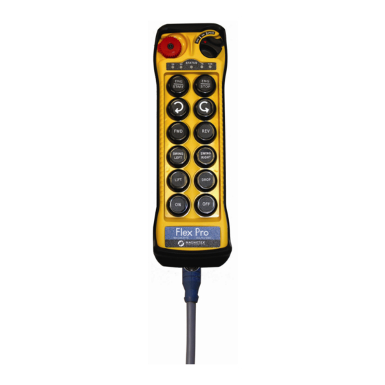
- Page 1 Flex Pro Tethered Controller Remote Control Equipment Instruction Manual 198-00132-R1 July 2011 © Copyright 2011 Magnetek Material Handling...
- Page 2 Service Information Your New Remote Control System Thank you for your purchase of Magnetek’s Enrange™ Flex Pro Tethered Controller. Without a doubt, our Flex Pro systems are the ultimate solution for providing precise, undeterred, and safe control of your material.
-
Page 3: Table Of Contents
5. Setup Installation of Tethered Controller Cable CAN Connector Pinout CAN Protocols 6. Operating Procedure General Operating Procedure Status Light Indicators & Warnings Push Button Error Table Trouble Shooting Tips Flex Pro Tethered Controller Instruction Manual July 2011 1 of 17... - Page 4 It is the responsibility of the owners, users and operators of the Magnetek Products to know, understand and follow all of these requirements. It is the responsibility of the employer to make its employees aware of all of the above listed requirements and to make certain that all operators are properly trained.
-
Page 5: Introduction
Full compliance – All systems are fully compliant with the European Directives (Safety, EMC, R&TTE, and Machinery) and Industry Canada Specifications (IC). Flex Pro Tethered Controller Instruction Manual July 2011 3 of 17... -
Page 6: Remote Controlled Safety
The following information is intended to be used in conjunction with other rules or regulations already in existence. It is important to read all of the safety information contained in this section before installing or operating the Remote Control System. Flex Pro Tethered Controller Instruction Manual July 2011... - Page 7 Remote controlled equipment should not be operated by any person with insufficient eyesight or hearing or by any person who may be suffering from a disorder or illness, is taking any medication that may cause loss of equipment control, or is under the influence of alcohol or drugs. Flex Pro Tethered Controller Instruction Manual July 2011...
- Page 8 operate any damaged or malfunctioning crane, hoist, lifting device or other material handling equipment Flex Pro Tethered Controller Instruction Manual July 2011 6 of 17...
- Page 9 PERFORMANCE OR SAFETY CONCERNS ARE OBSERVED, THE EQUIPMENT SHOULD IMMEDIATELY BE TAKEN OUT OF SERVICE AND BE REPORTED TO THE SUPERVISOR. DAMAGED AND INOPERABLE TETHERED CONTROLLER EQUIPMENT SHOULD BE RETURNED TO MAGNETEK FOR EVALUATION AND REPAIR. FAILURE TO FOLLOW THIS WARNING COULD RESULT IN SERIOUS INJURY OR DEATH AND DAMAGE TO EQUIPMENT.
-
Page 10: General Controller Information
Push Button #10 4. Push Button #4 Push Button #11 5. Push Button #5 Push Button #12 NOTE: Push Buttons #9-#12 are not present on the Flex Pro 8 Module Flex Pro Tethered Controller Instruction Manual July 2011 8 of 17... -
Page 11: Internal Illustration (Pro 12 Configuration)
B. Internal Illustration (Pro 12 Configuration) (Fig. 03) (Fig. 04) Encoder Board I-CHIP CAN Module Dip-Switch Status LED Display CAN Connector Function LED Displays NOTE: Flex Pro 8 Module will differ slightly Flex Pro Tethered Controller Instruction Manual July 2011 9 of 17... -
Page 12: Types Of Buttons
C. Types of Buttons The buttons used on the Flex Pro tethered controller are fully proportional, stepless push buttons with an output that varies 0-100% (based on how far the button is depressed). It is possible to model the stepless buttons as an On/Off momentary switch, On/Off latched switch, 2 Speed button, or a 3 Speed button. -
Page 13: Dip-Switch Settings
Bits 6 and 7 on the dip-switch allows the user to define a time after which, if no buttons on the controller are pressed, the Flex Pro tethered controller will send an OFF command to the equipment and power down. To restart, the user must turn the On/Off/Start switch to the Off position, then back to On again to resume operation. -
Page 14: Setup
CAN connector receptacle. Twist the locking ring on the CAN plug clockwise to tighten it down and prevent accidental disengagement. CAN Connector Pinout Flex Pro Tethered Controller Instruction Manual July 2011 12 of 17... -
Page 15: Can Protocols
CAN Protocols The standard CAN messages that the Flex PRO tethered controller transmits are J1939. These messages are shown below. For custom messaging, consult the factory. Flex Pro Tethered Controller Instruction Manual July 2011 13 of 17... - Page 16 Flex Pro Tethered Controller Instruction Manual July 2011 14 of 17...
-
Page 17: Operating Procedure
“Start” position for up to 2 seconds. This will activate the E-Stop on the equipment. Thereafter, the same “Start” position will become an auxiliary function with momentary contact. (Fig. 12) Flex Pro Tethered Controller Instruction Manual July 2011 15 of 17... -
Page 18: Status Light Indicators & Warnings
START function). Stop command initiated with equipment Solid Red ESTOP deactivated. Voltage goes below 1.9V at initial power on - controller Solid Red power shuts off. Flex Pro Tethered Controller Instruction Manual July 2011 16 of 17... -
Page 19: Push Button Error Table
“START” position for up to 2.0 seconds (Improper startup & and then release. settings) Make sure that the controller handset has the Incorrect CAN ID correct CAN ID. Flex Pro Tethered Controller Instruction Manual July 2011 17 of 17... - Page 20 Enrange Flex Pro™ Tethered 8 and 12 Button Technical Specifications Controller Specification Controller Component Specifications ** Note: Each button can be configured as proportional, Temperature Range: -25°C to 75°C (-13°F to 167°F) on/off momentary, or on/off latched. Other custom configurations are available.
- Page 21 Enrange Flex Pro™ Tethered 8 and 12 Button Technical Specifications LAYOUT OF FLEX 12 BUTTON E. Emergency Stop Button Push Button #6 Strap Ring S. Removable Power Key Switch 7. Push Button #7 System Information 1. Push Button #1 Push Button #8 Machine Number 2.
Need help?
Do you have a question about the Flex Pro Tethered Controller and is the answer not in the manual?
Questions and answers