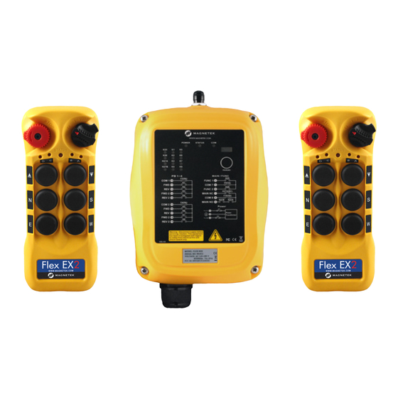
Magnetek Flex EX2 series Instruction Manual
Radio remote control systems
Hide thumbs
Also See for Flex EX2 series:
- Instruction manual (84 pages) ,
- Quick reference manual (9 pages) ,
- Charging instructions (2 pages)

Related Manuals for Magnetek Flex EX2 series


Summary of Contents for Magnetek Flex EX2 series
- Page 1 Flex EX2 Receiver Select Systems Radio Control Equipment Instruction Manual Part Number: 191-50000-MRS0F R00 August 2018 ©Copyright 2018 Magnetek Material Handling...
- Page 2 Page Intentionally Left Blank Flex EX2 Receiver Select Instruction Manual August 2018 Page 2 of 39...
-
Page 3: Table Of Contents
Table of Contents Introduction............................7 Radio Controlled Safety ........................8 Critical Installation Considerations ....................9 General............................9 Persons Authorized to Operate Radio Controlled Cranes............9 Safety Information and Recommended Training for Radio Controlled Equipment Operators..10 Transmitter Unit.......................... 11 Pre-Operation Test........................11 Batteries ............................. - Page 4 6.4.2 Receiver Status Indications ....................38 6.4.3 Receiver Power Indications ....................38 6.4.4 Receiver COM Indications ..................... 38 General Specifications ........................39 Flex EX2 Receiver Select Instruction Manual August 2018 Page 4 of 39...
- Page 5 SERVICE INFORMATION Your New Radio Remote Control System Thank you for your purchase of Magnetek’s Flex EX2 Radio Remote Equipment Control. Magnetek has set a whole new standard in radio remote performance, dependability, and value with this unique new line of handheld transmitters.
- Page 6 Magnetek Products to know, understand and follow all of these requirements. It is the responsibility of the owner of the Magnetek Products to make its employees aware of all of the above listed requirements and to make certain that all operators are properly trained. No one should use Magnetek Products prior to becoming familiar with and being trained in these requirements.
-
Page 7: Introduction
1 Introduction The Flex EX2 radio remote control systems are designed for control of industrial equipment and machinery such as overhead traveling cranes, jib cranes, gantry cranes, tower cranes, electric hoists, winches, monorails, conveyor belts, mining equipment and other material handling equipment where wireless control is preferred. -
Page 8: Radio Controlled Safety
2 Radio Controlled Safety WARNINGS and CAUTIONS Throughout this document WARNING and CAUTION statements have been deliberately placed to highlight items critical to the protection of personnel and equipment. WARNING WARNING indicates a potentially hazardous situation which, if not avoided, could result in death or serious injury. -
Page 9: Critical Installation Considerations
2.1 Critical Installation Considerations WARNING Prior to installation and operation of this equipment, read and develop an understanding of the contents of this manual and the operation manual of the equipment or device to which this equipment will be interfaced. Failure to follow this warning could result in serious injury or death and damage to equipment. -
Page 10: Safety Information And Recommended Training For Radio Controlled Equipment Operators
Radio controlled equipment should not be operated by any person with insufficient eyesight or hearing or by any person who may be suffering from a disorder or illness that may cause them to lose control of the equipment, is taking any medication that may cause loss of equipment control, or is under the influence of alcohol or drugs. -
Page 11: Transmitter Unit
Damaged and inoperable radio controller equipment should be returned to Magnetek for evaluation and repair. Failure to follow this warning could result in serious injury or death and damage to equipment. -
Page 12: General System Information
3 General System Information 3.1 RS System Types FLEX-8EX2-2RS-3M FLEX-8EX2-3RS-5M FLEX-8EX2-2RS-4M FLEX-8EX2-3RS-6M Flex EX2 Receiver Select Instruction Manual August 2018 Page 12 of 39... - Page 13 FLEX-8EX2-4RS-8M FLEX-12EX2-4RS-6M FLEX-12EX2-5RS-8M FLEX-12EX2-6RS-10M Flex EX2 Receiver Select Instruction Manual August 2018 Page 13 of 39...
- Page 14 FLEX-12EX2-4RS-7M FLEX-12EX2-5RS-9M Flex EX2 Receiver Select Instruction Manual August 2018 Page 14 of 39...
-
Page 15: Transmitter
3.2 Transmitter 3.2.1 External Illustration (8EX2) STOP Button Pushbutton 6 (PB6) Power Key Switch Pushbutton 7 (PB7) Status LED Indicator Pushbutton 8 (PB8) Pushbutton 1 (PB1) Future Feature Pushbutton 2 (PB2) Battery Cover Screw Pushbutton 3 (PB3) System Information Pushbutton 4 (PB4) Lanyard and Waist Belt Attachment Slot Pushbutton 5 (PB5) -
Page 16: External Illustration (12Ex2)
3.2.2 External Illustration (12EX2) STOP Button Pushbutton 8 (PB8) Power Key Switch Pushbutton 9 (PB9) Status LED Indicator Pushbutton 10 (PB10) Pushbutton 1 (PB1) Pushbutton 11 (PB11) Pushbutton 2 (PB2) Pushbutton 12 (PB12) Pushbutton 3 (PB3) Future Feature Pushbutton 4 (PB4) Battery Cover Screw Pushbutton 5 (PB5) System Information... -
Page 17: Internal Illustration (8Ex2)
A/B/C/D LED Indicators Programming Port* * The programming port is only used for updating the transmitter firmware. It is not used with the IR Programmer. For more information, contact Magnetek field service. Flex EX2 Receiver Select Instruction Manual August 2018... -
Page 18: Internal Illustration (12Ex2)
A/B/C/D LED Indicators Programming Port* * The programming port is only used for updating the transmitter firmware. It is not used with the IR Programmer. For more information, contact Magnetek field service. Flex EX2 Receiver Select Instruction Manual August 2018... -
Page 19: Receiver
3.3 Receiver 3.3.1 External Illustration External RP-TNC Antenna Port Remote Pairing Button COM LED Indicator System Information Status LED Indicator Cord Grip Power LED Indicator Mounting Bracket Output Relay LED Indicators Mounting Bracket Release Infrared Sensors Flex EX2 Receiver Select Instruction Manual August 2018 Page 19 of 39... -
Page 20: Internal Illustration
3.3.2 Internal Illustration Decoder Board Function Jumpers RF Transceiver Board Channel Dipswitch INT/EXT Antenna Jumpers AC Line Filter/Relay Board Programming Port Power Transformer Function Dipswitches Flex EX2 Receiver Select Instruction Manual August 2018 Page 20 of 39... -
Page 21: Function Settings
4 Function Settings 4.1 Transmitter 4.1.1 Transmitter Firmware Version 1. Rotate the power switch key to OFF ( 0 ) position. 2. With the STOP button elevated, press and hold PB1 and PB3 at the same time. 3. Rotate the power switch key to ON ( I ) position. 4. -
Page 22: Remote Pairing
5. Change transmitter channel by pressing PB1 to increment the units (+1) and PB2 to increment the tens (+10). For example, pressing PB2 two times and then PB1 four times is channel 24 (Status LED blinks 2 greens and 4 reds). 6. -
Page 23: Transmitter Output Power Settings
(press and hold PB3) 4.1.5 Transmitter Output Power Settings The transmitter is set to 1mW by default as that is the maximum allowed due to FCC regulations. If a different output power is required, please contact Magnetek field service. Dipswitch Output Power... -
Page 24: Transmitter Inactivity Timer Settings
By default, the sensor is disabled. When the sensor is enabled and a drop is detected, the receiver MAIN relays are deactivated. Please contact Magnetek field service for more details. Dipswitch... -
Page 25: Infrared Transmitter Settings
The IR programmer unit can be used to set the system serial number, channel, type setting, RS function setting, and many others. Please refer to the Flex IR Programmer Manual or contact Magnetek field service for more details. • All transmitters in a system are set to the same serial number and assigned channel. - Page 26 Transmitter Dipswitch Settings Transmitter Type Non-Interlocked Interlocked Non-Interlocked Interlocked Non-Interlocked Interlocked Non-Interlocked Interlocked Non-Interlocked Interlocked X = Not used Type B Type C Type D Type E Type F Flex EX2 Receiver Select Instruction Manual August 2018 Page 26 of 39...
-
Page 27: Receiver
1 2 3 * Channel X → channel set on the channel dipswitch. ** Contact Magnetek field service if your application requires scanning more than 4 channels. Example: If the first 6 dipswitch positions are set to channel 01 (000001), when set to 2-channel scanning (type 2 above) the receiver will scan only channel 01 and 02. -
Page 28: Dipswitch Settings
4.2.3 Dipswitch Settings # of Relays Function Descriptions Settings Used 4 output relays Closed/Closed relay action at 2nd speed 00000010 (separate 2nd speed output relays) 3 output relays Closed/Closed relay action at 2nd speed 00000100 (shared 2nd speed output relay) 4.2.4 Jumper Settings Jumper setting applies to functions such as the receiver... -
Page 29: Infrared Receiver Settings
Infrared Receiver Settings The IR programmer unit can be used to set the system serial number, channel, type setting, function relay settings, and many others. Refer to the Flex IR Programmer Manual or contact Magnetek field service for more details. Presets: •... -
Page 30: System Channels Table
4.2.7 System Channels Table The following dipswitch settings only apply to setting the channel in the receiver when using the assigned channel scheme (see Section 4.1.3 on page 21). Primary Secondary Primary Secondary Dipswitch Channel Channel Dipswitch Channel Channel Setting Frequency Frequency Setting... -
Page 31: Receiver Installation
5 Receiver Installation 5.1 Output Relay Contact Diagrams 5.1.1 Flex 4EX2 • For 9-36VDC power supply, wire #1 corresponds to the negative charge (-) and wire #3 corresponds to the positive charge (+). Wire #2 is for GROUND. • Due to the possibility of voltage spikes on the contactors, suppressors are required on contactors being driven by Flex relays. -
Page 32: Step-By-Step Installation
5.3 Step-by-Step Installation Mounting Bracket Type 1 Mounting Bracket Type 2 Flex EX2 Receiver Select Instruction Manual August 2018 Page 32 of 39... - Page 33 1. For best reception the location of the receiver should be visible to the operator at all times. 2. The location selected should not be exposed to high levels of electric noise. Mounting the receiver next to an unshielded variable- frequency drive may cause radio interference.
- Page 34 Install Mounting Bracket Type 1 Mounting Bracket Type 2 Remove Mounting Bracket Type 1 Mounting Bracket Type 2 Flex EX2 Receiver Select Instruction Manual August 2018 Page 34 of 39...
-
Page 35: Operating Procedures
6 Operating Procedures 6.1 General Operation 1. Reset the STOP button located on the top left hand corner of the transmitter by rotating it clockwise or counterclockwise. The button will pop up. Turn on the transmitter power by inserting the power switch key and rotate to ON ( I ) position. →... -
Page 36: Changing Batteries
7. Turn off the transmitter power by rotating the power switch key counterclockwise to OFF ( 0 ) position. It will disconnect the transmitter power and the receiver MAIN relays altogether. Turn it further counterclockwise to release the key. 6.2 Changing Batteries Change transmitter batteries (“AA”... -
Page 37: System Status Light Indications
6.4 System Status Light Indications 6.4.1 Transmitter Status Indications Type Display Type Indication Voltage below 1.8V at initial Solid red power on or during operation Voltage below 1.75V during 3 red blinks and then off operation (receiver MAIN relays shut off) Voltage below 1.85V during 1 red blink followed by a operation... -
Page 38: Flex Ex2 Receiver Select Instruction Manual August
6.4.2 Receiver Status Indications Type Display Type (Green & Red) Indication Fast green blinks Decoding in process Slow green blinks Decoding on standby Receiver MAIN relays jammed 2 red blinks or defective 3 red blinks Decoding processors defective 4 red blinks Receiving RF board defective Incorrect transmitter serial Fast red blinks... -
Page 39: General Specifications
7 General Specifications Frequency Range: 433.050 MHz - 439.600 MHz Number of Channels: 62 channels Channel Spacing: 50 KHz Modulation: Digital Frequency Modulation based on Manchester Code, 20-bit address, 32-bit CRC and Hamming Code. Encoder & Decoder: Microprocessor-controlled Transmitting Range: >100 meters (300 feet) Hamming Distance: >6...
Need help?
Do you have a question about the Flex EX2 series and is the answer not in the manual?
Questions and answers