
Related Manuals for Magnetek Flex 8RS System


Summary of Contents for Magnetek Flex 8RS System
- Page 1 Flex 8RS System Radio Control Equipment Instruction Manual 0-FLEX-8RS-ME R1 December 2012 © Copyright 2012 Magnetek Material Handling...
-
Page 2: Service Information
Service Information Your New Radio System Thank you for your purchase of Magnetek’s Enrange™ Flex EX radio remote control system. Without a doubt, our Flex EX system is the ultimate solution for providing precise, undeterred, and safe control of your material. - Page 3 It is the responsibility of the owners, users and operators of the Magnetek Products to know, understand and follow all of these requirements. It is the responsibility of the employer to make its employees aware of all of the above listed requirements and to make certain that all operators are properly trained.
-
Page 4: Table Of Contents
7.2.3 Receiver SQ Light Indication ......................34 7.2.4 Receiver POWER Light Indication ....................34 7.2.5 Receiver COM Light Indication......................34 7.3 TROUBLE SHOOTING TIPS ........................35 8. SYSTEM SPECIFICATIONS ......................... 36 Flex 8RS System Instruction Manual December 2012 1 of 36... -
Page 5: Introduction
Full compliance – All systems are fully compliant with the FCC Part-15 Rules, European Directives (Safety, EMC, R&TTE, and Machinery), and Industry Canada Specifications (IC). Flex 8RS System Instruction Manual December 2012 2 of 36... -
Page 6: Radio Controlled Safety
The following information is intended to be used in conjunction with other rules or regulations already in existence. It is important to read all of the safety information contained in this section before installing or operating the Radio Control System. Flex 8RS System Instruction Manual December 2012 3 of 36... -
Page 7: Critical Installation Considerations
Radio controlled equipment should not be operated by any person with insufficient eyesight or hearing or by any person who may be suffering from a disorder or illness, is taking any medication that may cause loss of equipment control, or is under the influence of alcohol or drugs. Flex 8RS System Instruction Manual December 2012 4 of 36... -
Page 8: Safety Information And Recommended Training For Radio Controlled Equipment Operators
operate any material handling equipment using a damaged controller because the unit may be unsafe Flex 8RS System Instruction Manual December 2012 5 of 36... -
Page 9: Transmitter Unit
OUT OF SERVICE AND BE REPORTED TO THE SUPERVISOR. DAMAGED AND INOPERABLE RADIO CONTROLLER EQUIPMENT SHOULD BE RETURNED TO MAGNETEK FOR EVALUATION AND REPAIR. FAILURE TO FOLLOW THIS WARNING COULD RESULT IN SERIOUS INJURY OR DEATH AND DAMAGE TO EQUIPMENT. -
Page 10: Battery Handling
2.11 SPECIFIC SYSTEM WARNINGS Below are some specific operating safety tips that should be strictly followed when operating a Flex 8RS system: Check the Status LED on the transmitter for any signs of low battery power (refer to page 33). -
Page 11: General System Information
-3 Receivers (A, B, and Bridge) TYPE C: A, B, C, D Receiver Select -8-Button Transmitter (bottom four buttons for A, B, C, D Select) -4 Receivers (A, B, C and D) Flex 8RS System Instruction Manual December 2012 8 of 36... -
Page 12: Transmitter Handset
Push Button #2 Strap Ring Push Button #4 System Information Push Button #6 System Channel Push Button #8 Crane Number Push Button #1 Battery Cover Push Button #3 FCC Information Flex 8RS System Instruction Manual December 2012 9 of 36... -
Page 13: Internal Illustration
3.2.2 Internal Illustration (Fig. 03) (Fig. 04) Encoder Board I-CHIP Aerial Antenna Function Dip-Switch Transmitting Module Channel Dip-Switch Status LED Display Battery Contact Mechanism Function LED Displays Flex 8RS System Instruction Manual December 2012 10 of 36... -
Page 14: Receiver Unit
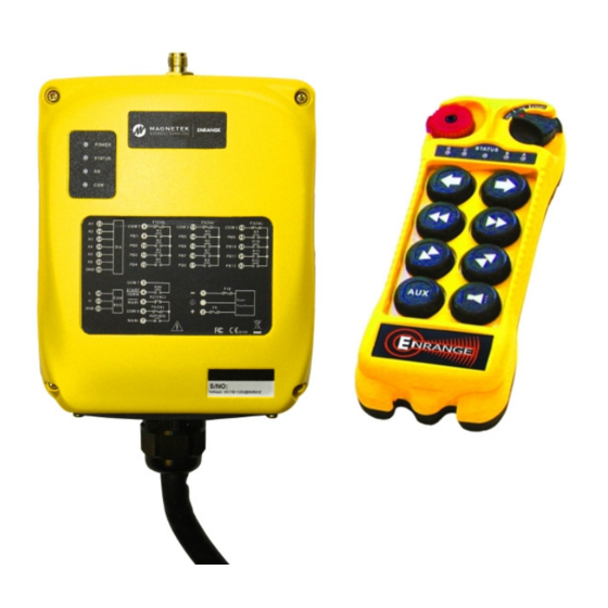
3.3 RECEIVER UNIT 3.3.1 External Illustration (Fig. 05) External Antenna Jack COM LED Display Power LED Display Output Contact Diagram Status LED Display Cord Grip SQ LED Display Flex 8RS System Instruction Manual December 2012 11 of 36... -
Page 15: Internal Illustration
3.3.2 Internal Illustration I-CHIP PORT SYSTEM FUNCTIONS TEST (Fig. 06) Receiving Module AC Line Filter Board Decoder + Relay Board Power Transformer Flex 8RS System Instruction Manual December 2012 12 of 36... -
Page 16: Function Settings
Top slot → “1” Bottom slot → “0” (Fig. 08) The above dip-switch setting “1 0 0 1 0 0” corresponds to “channel 36” in the system channels table on page 26. Flex 8RS System Instruction Manual December 2012 13 of 36... -
Page 17: Push Button Functions - Setup
FUNCTION DIP_SW 1, 2, 3 and 4 1 2 3 4 5 6 7 8 Refer to Relay Chart #1 TYPE B A,B,C,D interlock/non-interlock *UP (1): interlock, Down (0): non-Interlock Flex 8RS System Instruction Manual December 2012 14 of 36... - Page 18 1, 2, 3 and 4 1 2 3 4 5 6 7 8 Refer to Relay Chart # Refer to Relay Chart #1 TYPE C A,B,C,D interlock/non-interlock *UP (1): interlock, Down (0): non-interlock Flex 8RS System Instruction Manual December 2012 15 of 36...
- Page 19 Relay K5 – closed Relay K6 – open Relay K6 – open Relay K7 – not used Relay K7 – not used Relay K8 – closed Relay K8 – open Flex 8RS System Instruction Manual December 2012 16 of 36...
-
Page 20: Channel Change Via Push Buttons
CHANNEL dip-switch. Please note that when channel is set beyond channel 62 via PB1 and PB2 (i.e. channel 63, 68, 88, etc…), the system will recognize it as channel 62. Flex 8RS System Instruction Manual December 2012 17 of 36... -
Page 21: Optional 4-Digit Security Code
PB1 four times as your new security code (security code function disabled). If you do not remember the 4-digit security code, then you must contact your dealer or distributor for further assistance. Flex 8RS System Instruction Manual December 2012 18 of 36... -
Page 22: I-Chip
AUX – Set to NOR PWR – Set to 0 Timer – Set to 03 CH – 2 digit channel set per project (overwritten by dip switch settings) FUNC – set to 000 Flex 8RS System Instruction Manual December 2012 19 of 36... -
Page 23: Receiver Unit
Top slot → “1” Bottom slot → “0” (Fig. 13) The above dip-switch setting “1 0 0 1 0 0” corresponds to “channel 36” in the system channels table on page 26. Flex 8RS System Instruction Manual December 2012 20 of 36... -
Page 24: Receiver Auto-Scanning Settings
*If the first 6 dip-switch positions on the receiving module is set to Ch.01 (“000000” or “000001”), when set to 2-channel scanning (type-3 above), then the receiver will only scan Ch.01 and Ch.02. Flex 8RS System Instruction Manual December 2012 21 of 36... -
Page 25: Dip-Switch Settings
K3&4 or K7&8 on the decoder/relay board (refer to Fig. 14 & 15 below). I-CHIP PORT SYSTEM FUNCTIONS TEST RELAY FUNCTIONS (Fig. 14) (Fig. 15) PB5 & PB6 Flex 8RS System Instruction Manual December 2012 22 of 36... -
Page 26: Jumper Settings
Program system serial number/ID code and channel from decoder module (Blank) to I-CHIP. Program system serial number/ID code and channel from I-CHIP (Inserted) to decoder module. For system test only, receiver MAIN disabled. (Inserted) Flex 8RS System Instruction Manual December 2012 23 of 36... - Page 27 Jumper JP5 T/H Receiver A Open Open T/H Receiver B Open Open T/H Receiver C Open Open T/H Receiver D Open Open Transmitter Settings Function Dip Switch T/H Interlocked T/H Non-Interlocked Flex 8RS System Instruction Manual December 2012 24 of 36...
-
Page 28: I-Chip Programming Port
5.0A (clear) 5.0A (clear) 5.0A (clear) 5.0A (clear) 5.0A (clear) 5.0A (clear) 5.0A (clear) F9 ~ F10 0.5A (blue) 0.5A (blue) 0.5A (blue) 0.5A (blue) 1.0A (red) 1.0A (red) 2.0A (purple) Flex 8RS System Instruction Manual December 2012 25 of 36... -
Page 29: System Channels Table
434.475MHZ 111100 433.700MHZ 011101 434.500MHZ 111101 433.725MHZ 011110 434.525MHZ 111110 I-CHIP 433.750MHZ 011111 111111* * When set to all “1” the priority goes to the channel assigned inside the I-CHIP. Flex 8RS System Instruction Manual December 2012 26 of 36... -
Page 30: Receiver Installation
For 12 - 24VDC power supply, wire #1 corresponds to the negative charge (-) and wire #3 corresponds to the positive charge (+). Wire #2 is for GROUND. Wire #6 is for “Normal Close” and wire #8 is for “Normal Open” MAIN output. Flex 8RS System Instruction Manual December 2012 27 of 36... -
Page 31: Pre-Installation Precautions
2. The location selected should not be exposed to high levels of electric noise. Mounting the receiver next to an unshielded variable frequency drive may cause minor interference. Always locate the receiver as far away from the variable frequency drive as possible. Flex 8RS System Instruction Manual December 2012 28 of 36... -
Page 32: System Testing
3. Test the limit switches (if any) to see if they are working properly. 4. If your new remote control is replacing an existing pendant, make sure it is completely disconnected and placed in a safe location to prevent unwanted control commands. Flex 8RS System Instruction Manual December 2012 29 of 36... -
Page 33: Operating Procedure
Now press any push button on the transmitter handset to operate the crane or equipment. During transmitter inactivity (push buttons not pressed), the transmitter will automatically switch to standby mode, with an orange blink on the Status LED every 4-second interval. Flex 8RS System Instruction Manual December 2012 30 of 36... - Page 34 Turn off the transmitter power by rotating the power key counter-clockwise to “Off” position; it will disconnect the transmitter power and the receiver MAIN altogether. Turn it further counter-clockwise to release the key. Flex 8RS System Instruction Manual December 2012 31 of 36...
-
Page 35: Automatic Channel Scanning Operating Procedure
After changing the batteries also make sure that all screws are tightened to avoid water, moisture, dirt, grease, or other liquid penetration. (Fig. 19) ↓ Flex 8RS System Instruction Manual December 2012 32 of 36... -
Page 36: Status Light Indicators & Warnings
(prior to initiating the START function). Blinking green Pushbutton pressed, signal transmitted. Stop command initiated with receiver Slow red blinks MAIN deactivated. 1 orange blink every 4 seconds Transmitter on standby. Flex 8RS System Instruction Manual December 2012 33 of 36... -
Page 37: Receiver Status Light Indication
Display Type (Red) Indication Power to receiver No power to receiver 7.2.5 Receiver COM Light Indication Type Display Type (Red) Indication Power to relay board No power to relay board Flex 8RS System Instruction Manual December 2012 34 of 36... -
Page 38: Trouble Shooting Tips
Check input voltage connection. Check the system wiring again. Please refer to Outputs do not correspond to Incorrect output connection the output contact diagram inside this manual or transmitter on the receiver cover. Flex 8RS System Instruction Manual December 2012 35 of 36... -
Page 39: System Specifications
184mm (L) x 69mm (W) x 34mm (H) Receiver Dimension 180mm (L) x 150mm (W) x 82mm (H) Transmitter Weight 242g / 8.5oz Receiver Weight 2.1kg / 4.6lb (include output cable) Flex 8RS System Instruction Manual December 2012 36 of 36...
Need help?
Do you have a question about the Flex 8RS System and is the answer not in the manual?
Questions and answers