
Related Manuals for Magnetek flex 4es


Summary of Contents for Magnetek flex 4es
- Page 1 Flex EM/EX HazLoc Transmitter Engineered Remote Equipment Control Instruction Manual Part Number: 191-90001-M0090F R00 January 2018 ©Copyright 2017 Magnetek Material Handling...
- Page 2 Page Intentionally Left Blank Flex EM/EX HazLoc Transmitter Instruction Manual January 2018 Page 2 of 20...
-
Page 3: Table Of Contents
Table of Contents Radio Controlled Safety ........................5 Critical Installation Considerations ....................6 General............................6 Persons Authorized to Operate Radio Controlled Cranes............6 Safety Information and Recommended Training for Radio Controlled Equipment Operators..7 Transmitter Unit..........................8 Pre-Operation Test........................8 Batteries ............................ - Page 4 Page Intentionally Left Blank Flex EM/EX HazLoc Transmitter Instruction Manual January 2018 Page 2 of 20...
-
Page 5: Service Information
Your New Radio Remote Control System Thank you for your purchase of Magnetek’s Flex EM/EX Radio Remote Equipment Control System. Magnetek has set a whole new standard in radio-remote performance, dependability, and value with this unique line of handheld transmitters. -
Page 6: Warranty Information
It is the responsibility of the owners, users and operators of the Magnetek Products to know, understand and follow all of these requirements. It is the responsibility of the employer to make its employees aware of all of the above listed requirements and to make certain that all operators are properly trained. -
Page 7: Radio Controlled Safety
1 Radio Controlled Safety WARNINGS and CAUTIONS Throughout this document WARNING and CAUTION statements have been deliberately placed to highlight items critical to the protection of personnel and equipment. WARNING WARNING indicates a potentially hazardous situation which, if not avoided, could result in death or serious injury. -
Page 8: Critical Installation Considerations
2 Critical Installation Considerations WARNING Prior to installation and operation of this equipment, read and develop an understanding of the contents of this manual and the operation manual of the equipment or device to which this equipment will be interfaced. Failure to follow this warning could result in serious injury or death and damage to equipment. -
Page 9: Safety Information And Recommended Training For Radio Controlled Equipment Operators
Radio controlled equipment should not be operated by any person with insufficient eyesight or hearing or by any person who may be suffering from a disorder or illness that may cause them to lose control of the equipment, is taking any medication that may cause loss of equipment control, or is under the influence of alcohol or drugs. -
Page 10: Transmitter Unit
Damaged and inoperable radio controller equipment should be returned to Magnetek for evaluation and repair. Failure to follow this warning could result in serious injury or death and damage to equipment. -
Page 11: Battery Handling
Do not attempt to open the battery pack. Do not short-circuit the battery. For intrinsically safe environments, only use specified Magnetek intrinsically safe batteries. Keep the battery pack environment cool (for example, not in direct sunlight or close to a heating source) during charging, operation and storage. -
Page 12: General Transmitter Information
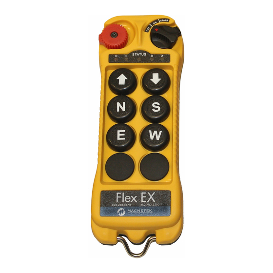
3 General Transmitter Information 3.1 External Illustration (12-Button Configuration) Fig. 1 Emergency STOP Button Pushbutton #6 Removable Power Key Pushbutton #8 Pushbutton #1 Pushbutton #10 Pushbutton #3 Pushbutton #12 Pushbutton #5 Strap Ring Pushbutton #7 System Information Pushbutton #9 System Channel Pushbutton #11 Unit Number Pushbutton #2... -
Page 13: Internal Illustration (12-Button Configuration)
3.2 Internal Illustration (12-Button Configuration) Fig. 2 Encoder Board I-CHIP Aerial Antenna Dip-Switch Bank 1 Transmitting Module Dip-Switch Bank 2 Status LED Display Battery Contact Mechanism Function LED Displays NOTE: The Flex 8EM or 8EX will differ slightly. 3.3 Types of Buttons Both the Flex EM and EX are offered in either 8-button or 12-button configurations. -
Page 14: Dip-Switch Settings
4 Dip-Switch Settings 4.1 System Channel Settings Set the transmitter channel by adjusting the dip-switch bank 2 located on the backside of the transmitter encoder board (refer to Fig. 2). Only the first 5 positions of the dip-switch are used for channel programming (refer to Fig. -
Page 15: Operating Procedure
5 Operating Procedure 5.1 General Operating Procedure 1. Reset the red emergency stop button located on the top left hand side of the transmitter handset by turning it either clockwise or counterclockwise. The red button will pop up. Fig. 5 2. -
Page 16: Changing Transmitter Batteries
5. Press any push button on the transmitter handset to operate the equipment. When a button is pressed, the Status LED will flash orange with a variable speed dependent on how far the button is pressed. The further a button is pressed, the faster the LED will flash. When no buttons are pressed, the Status LED will slowly flash green. -
Page 17: Status Lights Indicators And Warnings
5.3 Status Lights Indicators and Warnings Type Display Type Indication Slow green flash Transmitter on and in standby. (Normal operation) Button has been pressed and the unit is transmitting. The speed at Flashing orange which the orange LED flashes is directly related to how far down the button is pressed. -
Page 18: Push Button Error Table
5.4 Push Button Error Table Push Button Flex EM/EX HazLoc Transmitter Instruction Manual January 2018 Page 16 of 20... -
Page 19: Channel Configuration Settings
6 Channel Configuration Settings 6.1 FCC Statements Compliance Statement (Part 15.19) This device complies with Part 15 of FCC rules. Operation is subject to the following two conditions: This device may not cause harmful interference, and This device must accept any interference received, including interference that may cause undesired operation. -
Page 20: Channel Table
6.2 Channel Table Dip-switch Dip-switch Channel Frequency Channel Frequency Setting Setting 433.000 MHZ 00000 433.800 MHZ 10000 433.050 MHZ 00001 433.850 MHZ 10001 433.100 MHZ 00010 433.900 MHZ 10010 433.150 MHZ 00011 433.950 MHZ 10011 433.200 MHZ 00100 434.000 MHZ 10100 433.250 MHZ 00101... -
Page 21: Troubleshooting
Damaged and inoperable radio controller equipment should be returned to Magnetek for evaluation and repair. Failure to follow this warning could result in serious injury or death and damage to equipment. -
Page 22: Declaration Of Conformity
8 Declaration of Conformity Flex EM/EX HazLoc Transmitter Instruction Manual January 2018 Page 20 of 20...
Need help?
Do you have a question about the flex 4es and is the answer not in the manual?
Questions and answers