
Subscribe to Our Youtube Channel
Related Manuals for Magnetek FLEX-6EX


Summary of Contents for Magnetek FLEX-6EX
- Page 1 Flex 6EX System Radio Control Equipment Instruction Manual 0-FLEX-6EX-ME R3 March 2016 © Copyright 2016 Magnetek Material Handling...
-
Page 2: Service Information
Service Information Your New Radio System Thank you for your purchase of Magnetek’s Flex EX radio remote control system. Without a doubt, our Flex EX system is the ultimate solution for providing precise, undeterred, and safe control of your material. - Page 3 It is the responsibility of the owners, users and operators of the Magnetek Products to know, understand and follow all of these requirements. It is the responsibility of the employer to make its employees aware of all of the above listed requirements and to make certain that all operators are properly trained.
-
Page 4: Table Of Contents
Table of Contents 1. INTRODUCTION ............................5 2. RADIO CONTROLLED SAFETY ........................ 6 2.1 CRITICAL INSTALLATION CONSIDERATIONS ................... 7 2.2 GENERAL ............................7 2.3 PERSONS AUTHORIZED TO OPERATE RADIO CONTROLLED CRANES ........7 2.4 SAFETY INFORMATION AND RECOMMENDED TRAINING FOR RADIO CONTROLLED EQUIPMENT OPERATORS ........................ - Page 5 7.2.1 Transmitter STATUS Light Indication ................... 35 7.2.2 Receiver STATUS Light Indication ....................36 7.2.3 Receiver SQ Light Indication ....................... 36 7.2.4 Receiver POWER Light Indication ....................36 7.2.5 Receiver COM Light Indication ....................36 7.3 TROUBLE SHOOTING TIPS ......................
-
Page 6: Introduction
1. INTRODUCTION The Flex radio remote control systems are designed for control of industrial equipment and machinery such as overhead traveling cranes, jib cranes, gantry cranes, tower cranes, electric hoists, winches, monorails, conveyor belts, mining equipment and other material handling equipment where wireless control is preferred. Each Flex system consists of a transmitter handset and receiver unit. -
Page 7: Radio Controlled Safety
2. RADIO CONTROLLED SAFETY WARNINGS and CAUTIONS Throughout this document WARNING and CAUTION statements have been deliberately placed to highlight items critical to the protection of personnel and equipment. WARNING – A warning highlights an essential operating or maintenance procedure, practice, etc. which if not strictly observed, could result in injury or death of personnel, or long term physical hazards. -
Page 8: Critical Installation Considerations
2.1 CRITICAL INSTALLATION CONSIDERATIONS WARNING PRIOR TO INSTALLATION AND OPERATION OF THIS EQUIPMENT, READ AND DEVELOP AN UNDERSTANDING OF THE CONTENTS OF THIS MANUAL AND THE OPERATION MANUAL OF THE EQUIPMENT OR DEVICE TO WHICH THIS EQUIPMENT WILL BE INTERFACED. FAILURE TO FOLLOW THIS WARNING COULD RESULT IN SERIOUS INJURY OR DEATH AND DAMAGE TO EQUIPMENT. -
Page 9: Safety Information And Recommended Training For Radio Controlled Equipment Operators
OUT OF SERVICE AND BE REPORTED TO THE SUPERVISOR. DAMAGED AND INOPERABLE RADIO CONTROLLER EQUIPMENT SHOULD BE RETURNED TO MAGNETEK FOR EVALUATION AND REPAIR. FAILURE TO FOLLOW THIS WARNING COULD RESULT IN SERIOUS INJURY OR DEATH AND DAMAGE TO EQUIPMENT. -
Page 10: Transmitter Unit
BATTERY PROCEDURES CAN CAUSE BATTERIES TO EXPLODE OR DO OTHER SERIOUS DAMAGE. FAILURE TO FOLLOW THIS WARNING COULD RESULT IN SERIOUS INJURY OR DEATH AND DAMAGE TO EQUIPMENT. Use only batteries approved by Magnetek for the specific product. Do not dispose of a battery pack in fire; it may explode. -
Page 11: Battery Disposal
2.9 BATTERY DISPOSAL Before disposing of batteries consult local and governmental regulatory requirements for proper disposal procedure. 2.10 CRANE/LIFTING DEVICE SPECIFIC WARNINGS WARNING ALL EQUIPMENT MUST HAVE A MAINLINE CONTACTOR INSTALLED AND ALL TRACKED CRANES, HOISTS, LIFTING DEVICES AND SIMILAR EQUIPMENT MUST HAVE A BRAKE INSTALLED. FAILURE TO FOLLOW THIS WARNING COULD RESULT IN SERIOUS INJURY OR DEATH AND DAMAGE TO EQUIPMENT. -
Page 12: General Systems Information
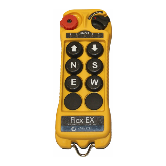
3. GENERAL SYSTEMS INFORMATION 3.1 TRANSMITTER HANDSET 3.1.1 External Illustration (Fig. 01) (Fig. 02) Emergency Stop Button Push Button #5 Removable Power Key Switch Strap Ring Push Button #2 System Information Push Button #4 System Channel Push Button #6 Crane Number Push Button #1 Battery Cover Push Button #3... -
Page 13: Internal Illustration
3.1.2 Internal Illustration (Fig. 03) (Fig. 04) Encoder Board I-CHIP Aerial Antenna Function Dip-Switch Transmitting Module Channel Dip-Switch Status LED Display Battery Contact Mechanism Function LED Displays Flex 6EX System Instruction Manual March 2016 Page 12 of 38... -
Page 14: Receiver Unit
3.2 RECEIVER UNIT 3.2.1 External Illustration (Fig. 05) External Antenna Jack (optional) SQ LED Display Power LED Display COM LED Display Status LED Display Output Contact Diagram Cord Grip Flex 6EX System Instruction Manual March 2016 Page 13 of 38... -
Page 15: Internal Illustration
3.2.2 Internal Illustration (Fig. 06) Receiving Module AC Line Filter/Relay Board Decoder/Relay Board Power Transformer Flex 6EX System Instruction Manual March 2016 Page 14 of 38... -
Page 16: Function Settings
4. FUNCTION SETTINGS 4.1 TRANSMITTER HANDSET 4.1.1 System Channel Settings CHANNEL (Fig. 07) Set the transmitter channel by adjusting the channel dip-switch located on the backside of the transmitter encoder board (refer to Fig. 07 above). Only the first six (6) positions are used for channel programming (refer to Fig. -
Page 17: Channel Change Via Push Buttons
4.1.2 Channel Change via Push Buttons Other than CHANNEL dip-switch on the encoder board, the transmitter channel can also be changed directly on the push buttons. Please refer to the instructions below on how to change the transmitter channel via push buttons. Press and hold PB1, PB2 and PB3 and rotate the power key to START position at the same time. -
Page 18: Optional 4-Digit Security Code
4.1.3 Optional 4-Digit Security Code The 4-digit Security Code is an optional feature that can be programmed into the transmitter to allow operation only to those who know the code. If this feature is desired, set up as follows: Prior to rotating the transmitter power key-switch to START position to begin operation, you first enter a 4-digit security code in order to proceed further. -
Page 19: I-Chip
4.1.4 I-CHIP The I-CHIP functions in a way that is very similar to a SIM card inside a mobile phone, which stores system information such as your telephone number, account number, phone book and other settings. I-CHIP works exactly the same way, as it stores information such as system serial number/ID code, channel and push button configurations. -
Page 20: Receiver Unit
4.2 RECEIVER UNIT 4.2.1 System Channel Settings (Fig. 10) Even though the Flex system is equipped with an automatic channel scanning mode, the user can also set the receiver channel manually. Please refer to page 33 on how automatic channel scanning receiver works. -
Page 21: Output Relay Configurations
4.2.2 Output Relay Configurations 4.2.2.1 Output Relay Types a. Three (3) output relays per motion – shared 2 speed output relay Output relays with Forward 1 speed (F1), Reverse 1 speed (R1) and Forward/Reverse 2 speed (F/R2). Forward and Reverse 2 speed (F/R2) shared the same output relay. -
Page 22: Start/Aux Function
b. 4-output relays configuration with Opened/Closed contact at 2 speed At 2 speed, only the 2 speed (F2 or R2) output relay is closed (refer to page 23 on how to set to this function). c. 4-output relays configuration with Closed/Closed contact at 2 speed At 2 speed, both 1... -
Page 23: Auxiliary Stop Push Button Function
4.2.2.6 Auxiliary STOP Push Button Function The auxiliary STOP function acts as a 2 emergency stop button. Other than by emergency stop button and transmitter power key switch, the receiver MAIN is also deactivated when this auxiliary stop push button is pressed (refer to page 24 on how to set to this function). STOP 4.2.3 Receiver Auto-Scanning Settings Receiver Channel Dip-switch... -
Page 24: Dip-Switch Settings
4.2.4 Dip-Switch Settings 4.2.4.1 Interlocked Functions Interlocked means the two adjacent push buttons cannot be activated simultaneously as they will cancel each other out. Interlocked settings are usually applied to forward and reverse motions. Each dip-switch on the decoder module corresponds to one (1) motion or two (2) adjacent push buttons (refer to Fig. -
Page 25: Non-Interlocked Functions
4.2.4.2 Non-Interlocked Functions Contrary to interlocked settings, non-interlocked settings allow the two adjacent push buttons be used simultaneously. Non-interlocked settings are usually applied to a crane’s auxiliary functions, such as lights, horn, 3 speed and auxiliary stop. Each dip-switch on the decoder module corresponds to one (1) motion or two (2) adjacent push buttons (left &... -
Page 26: Jumper Settings
4.2.5 Jumper Settings Jumper settings are applied to functions such as main-disconnect time, Start function, system information (serial number/ID code) programming, and system testing. Jumpers #1 - #7 are located on the decoder/relay board between the receiving RF module and the output relays (refer to Fig.14 below). -
Page 27: I-Chip Programming Port
4.2.6 I-CHIP Programming Port I-CHIP PORT I-CHIP PORT SYSTEM FUNCTIONS TEST (Fig. 15) The I-CHIP programming port, located on the decoder module (refer to Fig. 15 above) inside the receiver, is designed for the purpose of transferring a system serial number/ID code from the I-CHIP to the receiver or vice versa. -
Page 28: System Channels Table
5. SYSTEM CHANNELS TABLE Dip-switch Dip-switch Channel Frequency Channel Frequency Setting Setting 433.000MHZ 000000 433.775MHZ 100000 433.000MHZ 000001 433.800MHZ 100001 433.025MHZ 000010 433.825MHZ 100010 433.050MHZ 000011 433.850MHZ 100011 433.075MHZ 000100 433.875MHZ 100100 433.100MHZ 000101 433.900MHZ 100101 433.125MHZ 000110 433.925MHZ 100110 433.150MHZ 000111 433.950MHZ... -
Page 29: Recevier Installation
6. RECEVIER INSTALLATION 6.1 OUTPUT RELAY CONTACT DIAGRAM For 3-relay (shared 2 speed) and 4-relay (separate 2 speed) configurations please refer to page 20. For 4-relay closed/closed and 4-relay opened/closed relay configurations please refer to page 20. For 12-24VDC power supply, wire #1 corresponds to the negative charge (-) and wire #3 corresponds to the positive charge (+). -
Page 30: Pre-Installation Precautions
6.2 PRE-INSTALLATION PRECAUTIONS 1. Make sure the transmitter and receiver have identical serial number/ID codes and channels. 2. Make sure the receiver is not set to the same channel as any other systems in use in the surrounding area. 3. Make sure that the crane or equipment is working properly prior to installation. 4. - Page 31 1. For best reception the location of the receiver should be visible to the operator at all time. 2. The location selected should not be exposed to high levels of electric noise. Mounting the receiver next to an unshielded variable frequency drive may cause minor interference. Always locate the receiver as far away from the variable frequency drive as possible.
-
Page 32: System Testing
6.4 SYSTEM TESTING 1. Turn on the power source to the receiver and test the MAIN relay output by pressing the red emergency stop button and observe that it properly opens and closes the mainline disconnect contactor. 2. Test the operation of each function to ensure it corresponds to the transmitter direction labels or the pendant it is replacing. -
Page 33: Operating Procedure
7. OPERATING PROCEDURE 7.1 TRANSMITTER OPERATION 7.1.1 General Operating Procedure Reset the red emergency stop button located on the top left hand side of the transmitter handset by rotating it either clockwise or counter clockwise. The red button will pop up. Turn on the transmitter power by inserting the black-colored key into the power key slot (located on the top right hand side of the transmitter handset), and rotate it clockwise to “On”... -
Page 34: Automatic Channel Scanning Operating Procedure
In case of an emergency, pressing down the red emergency stop button will immediately disconnect the receiver MAIN and as well as the transmitter power. To resume operation, rotate the red button clockwise or counter clockwise, and it will pop up. Then rotate the power key-switch to START position for up to 1.0 second to activate all transmitter push button functions and the receiver MAIN (depends on JP3 setting on page 25). -
Page 35: Changing Transmitter Batteries
7.1.3 Changing Transmitter Batteries Change the transmitter batteries by unscrewing the battery cover located on the backside of the transmitter (refer to Fig. 17 below). During battery installation make sure that the blue ribbon is centered between the two batteries. After changing the batteries also make sure that all screws are tightened to avoid water, moisture, dirt, grease, or other liquid penetration. -
Page 36: Status Light Indicators & Warnings
7.2 STATUS LIGHT INDICATORS & WARNINGS 7.2.1 Transmitter STATUS Light Indication Type Display Type Indication Voltage below 1.9V at initial power on - transmitter power and receiver MAIN shuts off. Constant red Voltage below 1.8V during operation - transmitter power and receiver MAIN shuts off. 1 red blink followed by a 2- Voltage goes below 1.85V during operation - second pause... -
Page 37: Receiver Status Light Indication
7.2.2 Receiver STATUS Light Indication Type Display Type Indication Fast green blinks Decoding in process Slow green blinks Decoding on standby Two red blinks Receiver MAIN jammed or defective Fast red blinks Incorrect transmitter serial number/ID code Receiver under-voltage, LV output relay Constant red activated No light displayed... -
Page 38: Trouble Shooting Tips
7.3 TROUBLE SHOOTING TIPS Problems Possible Reasons Suggestions Transmitter has low battery Check the transmitter battery level. power Prior to turning on the transmitter power switch Emergency stop button make sure that the red emergency stop button is activated prior to startup elevated. -
Page 39: System Specifications
8. SYSTEM SPECIFICATIONS Frequency Range 433 - 434 MHz Frequency Deviation 12.5 KHz Number of Channels 62 channels Modulation Digital Frequency Modulation based on Manchester Code, 20bit address, 32bit CRC Parity Check and Hamming Code. Encoder & Decoder Microprocessor-controlled Transmitting Range >100 Meters / 300 Feet Frequency Control Synthesized PLL (Phase Lock Loop)
Need help?
Do you have a question about the FLEX-6EX and is the answer not in the manual?
Questions and answers
What does a blinking orange light after startup indicate
A blinking orange light after startup on a Magnetek FLEX-6EX indicates that the transmitter push button functions are locked.
This answer is automatically generated