
Subscribe to Our Youtube Channel
Related Manuals for Magnetek Flex Pro Series


Summary of Contents for Magnetek Flex Pro Series
- Page 1 Flex Pro Tethered Controller Remote Control Equipment Instruction Manual 198-00132 R05 April 2019 © Copyright 2019 Magnetek...
- Page 2 SERVICE INFORMATION Your New Remote Control System Thank you for your purchase of Magnetek’s Flex Pro Tethered Controller. Without a doubt, our Flex Pro systems are the ultimate solution for providing precise, undeterred, and safe control of your material. If your product ever needs modification or service, please contact one of our representatives at the following locations: U.S.
-
Page 3: Table Of Contents
Table of Contents PREFACE AND SAFETY ........................4 PRODUCT SAFETY INFORMATION ................... 4 INTRODUCTION ...........................5 REMOTE CONTROLLED SAFETY ......................6 GENERAL ............................. 7 PERSONS AUTHORIZED TO OPERATE REMOTE CONTROLLED CRANES ......7 SAFETY INFORMATION AND RECOMMENDED TRAINING FOR REMOTE CONTROLLED EQUIPMENT OPERATORS ........................8 CONTROLLER UNIT ........................ -
Page 4: Preface And Safety
It is the responsibility of the owners, users and operators of the Magnetek Products to know, understand and follow all of these requirements. It is the responsibility of the employer to make its employees aware of all of the above listed requirements and to make certain that all operators are properly trained. -
Page 5: Introduction
2 INTRODUCTION The Flex remote control systems are designed for control of industrial equipment and mobile machinery such as overhead traveling cranes, construction equipment, forestry equipment, mining equipment, rail equipment, drilling and trenching equipment, agriculture equipment, electric hoists, winches, monorails, conveyor belts, mining equipment and other material handling equipment where hardwired remote control is preferred. -
Page 6: Remote Controlled Safety
3 REMOTE CONTROLLED SAFETY WARNINGS and CAUTIONS Throughout this document WARNING and CAUTION statements have been deliberately placed to highlight items critical to the protection of personnel and equipment. WARNING – A warning highlights an essential operating or maintenance procedure, practice, etc. which if not strictly observed, could result in injury or death of personnel, or long term physical hazards. -
Page 7: General
WARNING PRIOR TO INSTALLATION AND OPERATION OF THIS EQUIPMENT, READ AND DEVELOP AN UNDERSTANDING OF THE CONTENTS OF THIS MANUAL AND THE OPERATION MANUAL OF THE EQUIPMENT OR DEVICE TO WHICH THIS EQUIPMENT WILL BE INTERFACED. FAILURE TO FOLLOW THIS WARNING COULD RESULT IN SERIOUS INJURY OR DEATH AND DAMAGE TO EQUIPMENT. -
Page 8: Safety Information And Recommended Training For Remote Controlled Equipment Operators
3.3 SAFETY INFORMATION AND RECOMMENDED TRAINING FOR REMOTE CONTROLLED EQUIPMENT OPERATORS Anyone being trained to operate remote controlled equipment should possess as a minimum the following knowledge and skills before using the remote controlled equipment. The operator should: • have knowledge of hazards pertaining to equipment operation •... -
Page 9: Controller Unit
TAKEN OUT OF SERVICE AND BE REPORTED TO THE SUPERVISOR. DAMAGED AND INOPERABLE RADIO CONTROLLER EQUIPMENT SHOULD BE RETURNED TO MAGNETEK FOR EVALUATION AND REPAIR. FAILURE TO FOLLOW THIS WARNING COULD RESULT IN SERIOUS INJURY OR DEATH AND DAMAGE TO EQUIPMENT. -
Page 10: General Controller Information
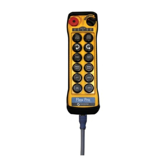
4 GENERAL CONTROLLER INFORMATION 4.1 EXTERNAL ILLUSTRATION (Pro 12 Configuration) Figure 1 Figure 2 E. Emergency Stop Button Push Button #6 Strap Ring S. Removable Power Key Switch 7. Push Button #7 System Information 1. Push Button #1 Push Button #8 CAN Connector 2. -
Page 11: Internal Illustration (Pro 12 Configuration)
4.2 INTERNAL ILLUSTRATION (Pro 12 Configuration) Figure 3 Figure 4 Encoder Board I-CHIP CAN Module Dip Switch Status LED Display CAN Connector Function LED Displays NOTE: The Flex Pro 8 Module will differ slightly. Flex Pro Tethered Controller Instruction Manual April 2019 Page 11 of 24... -
Page 12: Types Of Buttons
4.3 TYPES OF BUTTONS The buttons used on the Flex Pro tethered controller are fully proportional, stepless push buttons with an output that varies 0-100% (based on how far the button is depressed). It is possible to model the stepless buttons as an On/Off momentary switch, On/Off latched switch, 2 Speed button, or a 3 Speed button. -
Page 13: Dip Switch Settings
5 DIP SWITCH SETTINGS Figure 7 5.1 INACTIVITY TIME-OUT TIMER Bits 6 and 7 on the dip switch allows the user to define a time after which, if no buttons on the controller are pressed, the Flex Pro tethered controller will send an OFF command to the equipment and power down. -
Page 14: Setup
As such, the tethered controller will need to be wired to another power source. Typically Magnetek will provide a cable with flying leads that is used to wire the tethered controller to the receiver. The power and ground portions of this cable will need to be connected to an external power source for the tethered controller to properly operate. -
Page 15: Can Connector Pinout
6.3 CAN CONNECTOR PINOUT Flex Pro Tethered Controller Instruction Manual April 2019 Page 15 of 24... -
Page 16: J9139 Protocol
6.4 J9139 PROTOCOL The standard J1939 messages that the Flex Pro tethered controller transmits are shown below. For custom messaging, consult the factory. Flex Pro Tethered Controller Instruction Manual April 2019 Page 16 of 24... - Page 17 Flex Pro Tethered Controller Instruction Manual April 2019 Page 17 of 24...
-
Page 18: Canopen Protocol
The standard CANOpen messages that the Flex Pro tethered controller transmits are shown below. For custom messaging, consult the factory. Transmit PDO 1 CANopen 8bit Digital Inputs (1-8) Magnetek Device Transmit CAN ID Node Id + 0x180 Transmission Repetition Rate... - Page 19 Transmit PDO 2 CANopen 16bit signed analog Inputs (1-4) Magnetek Device Transmit CAN ID Node Id + 0x181 Transmission Repetition Rate 50ms Bit 7 Bit 6 Bit 5 Bit 4 Bit 3 Bit 2 Bit 1 Bit 0 Byte 1...
- Page 20 Transmit PDO 4 CANopen 16bit signed analog Inputs (9-12) Magnetek Device Transmit CAN ID Node Id + 0x183 Transmission Repetition Rate 50ms Bit 7 Bit 6 Bit 5 Bit 4 Bit 3 Bit 2 Bit 1 Bit 0 Byte 1...
-
Page 21: Operating Procedure
7 OPERATING PROCEDURE 7.1 GENERAL OPERATING PROCEDURE Reset the red emergency stop button located on the top left hand side of the controller handset by rotating it either clockwise or counter clockwise. The red button will pop up. Figure 9 Turn on the controller power by inserting the black-colored key into the power key slot located on the top right hand side of the controller handset and rotate it clockwise to the “On”... -
Page 22: Status Light Indicators And Warnings
Now press any push button on the controller handset to operate the equipment. When a button is pressed, the Status LED will flash orange with a variable speed dependent on how far the button is pressed. The further a button is pressed, the faster the LED will flash. -
Page 23: Push Button Error Table
7.3 PUSH BUTTON ERROR TABLE Push Button 7.4 TROUBLESHOOTING TIPS Problems Possible Reasons Suggestions Controller low power Check the CAN power supply. Prior to turning on the controller power switch Emergency stop button No response when make sure that the red emergency stop button is activated prior to startup elevated. -
Page 24: Declaration Of Conformity
8 DECLARATION OF CONFORMITY Flex Pro Tethered Controller Instruction Manual April 2019 Page 24 of 24...
Need help?
Do you have a question about the Flex Pro Series and is the answer not in the manual?
Questions and answers