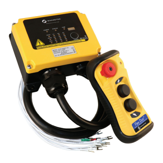
Magnetek Flex Duo Quick Reference Manual
Radio control equipment
Hide thumbs
Also See for Flex Duo:
- Quick reference manual (2 pages) ,
- Operator's manual (23 pages) ,
- Instruction manual (121 pages)
Advertisement
MRX Wiring Diagram
In the single speed model, relay K1 is for PB1 and relay K2 is for PB2.
Relay K3 is not used in the single speed model.
In the dual speed model, relay K1 is first speed for PB1, relay K2 is first speed for PB2, and relay K3 is shared
as a second speed for PB1 and PB2.
PB1
Relay
2
ND
Speed
1
K1
X
K2
K3
X
MAIN Relays K27A(NC), K27A and K27B change state when the system is turned on and remain latched while
the system is turned on. When the system is turned off, these relays revert to their normal state.
FUNC Relay K10 is an auxiliary relay that closes during the START / ON sequence and opens when PB1 and
PB2 are released.
For 9-36VDC power supply, wire #1 corresponds to the negative charge (-), wire #3 corresponds to the positive
charge (+), and wire #2 is for GROUND.
The circled numbers in the output diagrams above correspond to the wire numbers in the harness.
Suppressors are recommended on contactors being driven by Flex relays due to the possibility of voltage
spikes.
Distributed by Tri-State Equipment Company Inc.
N49 W13650 Campbell Drive
Menomonee Falls, WI 53051
sales@tsoverheadcrane.com
www.tsoverheadcrane.com
Tel: (314) 869-7200
PB1
PB2
PB2
ST
Speed OFF
1
ST
Speed
2
ND
Speed
X
X
X
X
Flex Duo Quick Reference Manual
September 2020 © Copyright 2020 Magnetek
NOTE: The full Flex Duo Instruction Manual can be found at www.columbusmckinnon.com/magnetek.
Consult the Instruction Manual for any desired feature not included in this quick reference manual.
191-32000-M001 R00
Flex Duo™
Radio Control Equipment
Quick Reference Manual
191-32000-M001 R00
September 2020
© Copyright 2020 Magnetek
Advertisement
Table of Contents

Summary of Contents for Magnetek Flex Duo
- Page 1 When the system is turned off, these relays revert to their normal state. NOTE: The full Flex Duo Instruction Manual can be found at www.columbusmckinnon.com/magnetek. FUNC Relay K10 is an auxiliary relay that closes during the START / ON sequence and opens when PB1 and Consult the Instruction Manual for any desired feature not included in this quick reference manual.
- Page 2 MCX antenna cable located on the RF/decoder board inside the receiver is connected and the upon quick installation. jumper is moved from the INT to the EXT position. The default operation of the Flex Duo system has the two pushbuttons configured as an interlocked pair to perform Standard Optional Mounting Bracket as motion control with the corresponding output relays setup for momentary contact closure.


Need help?
Do you have a question about the Flex Duo and is the answer not in the manual?
Questions and answers
is there an installation video. that can be sent to me?