Table of Contents
Advertisement
Quick Links
Please carefully read this manual, and save this manual for future use.
Before using this product, be sure to read "Read this first!" (pages 2 to 6).
PJ PSJ EJ ESJ
W0318TY0 -FJ
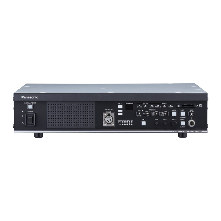
Operating Instructions
AK-UCU600P
Model No.
AK-UCU600PS
Model No.
AK-UCU600E
Model No.
AK-UCU600ES
Model No.
Camera Control Unit
ENGLISH
DVQP1734ZA
Advertisement
Table of Contents


Need help?
Do you have a question about the AK-UCU600P and is the answer not in the manual?
Questions and answers