Advertisement
Quick Links
Please carefully read this manual, and save this manual for future use.
Before using this product, be sure to read "Read this first!" (pages 2 to 6) .
W0316MN4017 -PS
Operating Instructions
AK-UCU500P
Model No.
AK-UCU500PS
Model No.
AK-UCU500E
Model No.
AK-UCU500ES
Model No.
Camera Control Unit
VQT5M18A-4 (E)
ENGLISH
Advertisement

Related Manuals for Panasonic AK-UCU500P


Summary of Contents for Panasonic AK-UCU500P
- Page 1 Operating Instructions Camera Control Unit AK-UCU500P Model No. AK-UCU500PS Model No. AK-UCU500E Model No. AK-UCU500ES Model No. Please carefully read this manual, and save this manual for future use.
- Page 2 Read this first! Read this first! WARNING: CAUTION Installation should only be performed by qualified RISK OF ELECTRIC SHOCK DO NOT OPEN installation personnel. Improper installation may result in the entire apparatus falling down and CAUTION: TO REDUCE THE RISK OF ELECTRIC SHOCK, causing injury.
- Page 3 Read this first! For AK-UCU500P, AK-UCU500PS IMPORTANT SAFETY INSTRUCTIONS 1) Read these instructions. 2) Keep these instructions. 3) Heed all warnings. 4) Follow all instructions. 5) Do not use this apparatus near water. 6) Clean only with dry cloth. 7) Do not block any ventilation openings. Install in accordance with the manufacturer’s instructions.
- Page 4 Fuse If you lose the fuse cover the plug must not be Fuse used until a replacement cover is obtained. A replacement fuse cover can be purchased from your local Panasonic Dealer. indicates safety information. - 4 -...
- Page 5 Read this first! EMC NOTICE FOR THE PURCHASER/USER OF THE APPARATUS 1. Applicable standards and operating environment (AK-UCU500E/ES) The apparatus is compliant with: • standards EN55103-1 and EN55103-2, and • electromagnetic environments E1, E2, E3 and E4. 2. Pre-requisite conditions to achieving compliance with the above standards <1>...
- Page 6 Read this first! Manufactured by: Panasonic Corporation, Osaka, Japan Importer’s name and address of pursuant to EU rules: Panasonic Marketing Europe GmbH Panasonic Testing Centre Winsbergring 15, 22525 Hamburg, Germany Disposal of Old Equipment Only for European Union and countries with recycling systems This symbol on the products, packaging, and/or accompanying documents means that used electrical and electronic products must not be mixed with general household waste.
- Page 7 Table of Contents Read this first! SD DETAIL HD PHASE Introduction SD PHASE How to View This Manual BAR ID About trademarks and registered trademarks RETURN SELECT About copyright MONITOR Illustrations and screen displays featured in the manual UHD SETTING Abbreviations UHD DETAIL Overview...
- Page 8 IP Images Web Screen Reference Connector pin assignment table Front panel Rear panel Front panel [G/L ON] indicator specifications Appearance Specifications Index - 8 -...
- Page 9 Introduction Introduction How to View This Manual About trademarks and registered trademarks ® ® ® ® ® ® ® ® Microsoft , Windows , Windows 7, Windows 8, Windows 8.1, Internet Explorer , ActiveX and DirectX are either registered trademarks or trademarks of Microsoft Corporation in the United States and other countries. Apple, Mac and OS X are registered trademarks of Apple Inc., in the United States and other countries.
- Page 10 For the purposes of this manual, the model numbers of the units are given as listed in the table below. Model number of unit Model number given in manual AK-HC5000G AK-HC5000 AK-HC5000GS AK-UC3000G AK-UC3000 AK-UC3000GS AK-HRP1000G AK-HRP1000G AK-HRP1005G AK-HRP1005 AK-UCU500P AK-UCU500PS AK-UCU500 AK-UCU500E AK-UCU500ES AK-MSU1000G AK-MSU1000 - 10 -...
- Page 11 Introduction Overview This camera control unit (CCU) is designed to be used with the studio handy camera (AK-HC5000; sold separately, AK-UC3000; sold sep- arately). Connect it to the studio handy camera (hereinafter referred to as the camera) with an optical fiber multi cable (sold separately). You can use the unit to input and output the video signals of various formats.* The unit supports 3G-HD/HD/SD-SDI outputs, analog composite outputs, HD/SD-SDI return inputs, VBS return inputs, and prompter inputs (HD-SDI, analog composite).
- Page 12 *3: Use is not possible with the 64-bit version of Internet Explorer Disclaimer of warranty IN NO EVENT SHALL Panasonic Corporation BE LIABLE TO ANY PARTY OR ANY PERSON, EXCEPT FOR REPLACEMENT OR REASONABLE MAINTENANCE OF THE PRODUCT, FOR THE CASES, INCLUDING BUT NOT LIMITED TO BELOW: ANY DAMAGE AND LOSS, INCLUDING WITHOUT LIMITATION, DIRECT OR INDIRECT, SPECIAL, CONSEQUENTIAL OR EXEMPLARY, ARISING OUT OF OR RELATING TO THE PRODUCT;...
- Page 13 4 GB to 32 GB SDXC memory cards are not supported. For the latest information not described in the Operating Instructions, refer to the following website. http://pro-av.panasonic.net/ Observe the following points when using and storing this unit. Avoid high temperature and humidity.
- Page 14 Introduction Features 4K, HD, and SD format simultaneous operation possible (when using AK-UC3000) As a standard feature, this unit incorporates 4K video (UHD) output, HD video signal output, and SD video signals that are available when this unit is used in combination with AK-UC3000. HD and SD format simultaneous operation possible (when using AK-HC5000) As a standard feature, this unit incorporates HS (high speed) video signal outputs, HD video signal outputs, and SD video signals.
- Page 15 After unpacking the product, dispose of the packaging material appropriately. Power cable Rack mount adapters* ……………2 “Mounting the rack mount adapters” (see page 18) for AK-UCU500P / AK-UCU500PS……………1 for AK-UCU500E / AK-UCU500ES……………2 *1: The screws for the rack mount adapters come attached to the unit. - 15 -...
- Page 16 This product includes MIT Licensed software. This product includes BSD Licensed software. For details on obtaining the source codes, visit the following website. http://pro-av.panasonic.net/ However, do not contact Panasonic for questions regarding obtained source codes. - 16 -...
- Page 17 Introduction Precautions for Installation In addition to the safety precautions given in “Read this first!”, also observe the following instructions. Be sure to ask your dealer to perform the installation and connection work for the unit. Connecting a power supply Be sure to use the power cable supplied with the unit.
- Page 18 Introduction Mounting the unit in a rack Mounting the rack mount adapters 1. Remove the setting legs (A) secured to the unit. Remove them using a Phillips screwdriver. 2. Mount the supplied rack mount adapters (B). Mounting screws are not supplied. Use mounting screws removed from the unit using a Phillips screwdriver. Tighten the mounting screws for rack mount adapters using a torque of 110 N·m or more.
- Page 19 Connection Connection System configuration Serial connection Use the optical fiber multi cable (sold separately) to connect the unit and camera. Use a ROP cable to connect the unit to the ROP (AK-HRP1000 / AK-HRP1005). For the connection procedure, see "Equipment connections." “Equipment connections”...
- Page 20 Connection Equipment connections Before proceeding with the connections, check that the power of the unit and camera is OFF. Use the optical fiber multi cable to connect the unit and camera. Connect only the AK-HC5000, AK-UC3000 camera: Do not connect any other model. Use a dedicated cable to connect the unit to the ROP.
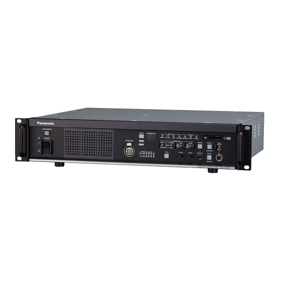
- Page 21 Parts and their functions Parts and their functions Front panel 1 [POWER] switch This is the unit’s power switch. Move it to the ON position to turn on the power. ON ( ) OFF ( [POWER] lamp This lights when [POWER] switch is set to ON and power is supplied to the unit. [CAMERA POWER] button When you press the [CAMERA POWER] button, the unit begins supplying power to the cam- era.
- Page 22 Parts and their functions Front panel 2 [STATUS] indicators Lights to indicate the unit status. [G/L ON] indicator Lights when the external sync signal is synchronized. “Front panel [G/L ON] indicator specifications” (see page 126) [FAN] indicator Lights when the rotation speed of the unit's cooling fan drops below the normal value. [ALARM] indicator Lights when the unit malfunctions.
- Page 23 Parts and their functions Front panel 3 [MENU] button When you hold down the [MENU] button, the menu screen is displayed on the picture monitor and the [MENU] button lights. If you hold down the [MENU] button while the menu is displayed, the menu closes and the [MENU] button turns off.
- Page 24 Parts and their functions Rear panel 1 [UHD/HS/HD/SD SDI OUT] con- UHD (connects to the AK-UC3000), HS (connects to the AK-HC5000), and 3G-HD, HD, SD nectors [1] to [4] video signal output connectors (BNC). Signals output can be selected from the CCU menu. “OUTPUT FORMAT(UHD)”...
- Page 25 Parts and their functions [REF] connectors These connectors (BNC) are for inputting reference signals. Black burst (BB) signals and tri-level sync signals can be input, and the type of signals input is recognized automatically.* When no cable is connected to the loop-through output connector (B), the connector is auto- matically terminated at 75 Ω.
- Page 26 Parts and their functions Rear panel 2 [LAN] connector It is the LAN connector (RJ45) for connecting the ROP (AK-HRP1000 / AK-HRP1005) with an IP connection. Use a switch hub and connect the devices with a 10BASE-T/100BASE-TX straight cable. This connector is for connecting a personal computer when configuring Web settings.
- Page 27 Picture monitor (PM) Picture monitor (PM) Picture monitor displays Display the camera statuses, warnings, and other information on the picture monitor using the operation panel of the ROP. Press the [CHARA] button (A) of the ROP to display the desired information. When [CHARA] is assigned to the [USER] button on the front panel of the unit (AK-UCU500), the same operation can also be car- ried out with the [USER] button.
- Page 28 Picture monitor (PM) Transition of displays When trouble is detected, warning information is automatically displayed on the picture monitor. Even if status information or operation information is already displayed on the picture monitor when trouble is detected, priority is given to the display of the warning information.
- Page 29 Picture monitor (PM) Information display This information is displayed on the picture monitor (PM). Warning displays The warning information is displayed when trouble is detected in the unit, camera, or optical fiber multi cable. - WARNING - CAM RCV LVL NG CCU RCV LVL NG Warning information displayed is cleared when the status returns to normal.
- Page 30 Picture monitor (PM) MEM:F5.6 F 4. 8 ------- --+-------- -- A. Camera number B. IRIS F value C. IRIS level D. IRIS memory E. TALLY INFO Set each item to be displayed on the [PM VIEW SETTING] screen that can be accessed by selecting [MAINTENANCE] on the CCU menu.
- Page 31 Picture monitor (PM) Status display screen CAM59.94i SCENE1 15 0 0 EX DZ×2 12dB - 2 .9 d B EX ×2 F.DROP FLIKE1 ND:***** MEM:F 4 .8 CC:***** 15000K CL O SE A. Camera number B. System format C. Scene file number Not displayed when SCENE FILE is set to OFF.
- Page 32 Picture monitor (PM) Item Display range Remarks BLACK SHADING The status of the black shading is displayed here. WHITE SHADING The status of the white shading is displayed here. FLARE The status of the FLARE is displayed here. GAMMA The status of the gamma correction is displayed here. BLACK GAMMA The status of the black gamma is displayed here.
- Page 33 Picture monitor (PM) Item Display range Remarks SCENE FILE The selected scene file is displayed here. SCENE0 to SCENE8 ASU REF FACTORY The reference file used during auto setup is displayed here. USER1 USER2 USER3 ASU MODE OUT FULL The auto setup mode is displayed here. OUT EASY Status displays (page 3 of 5) 3/5 -Status3-...
- Page 34 Picture monitor (PM) Item Display range Remarks SDI OUTPUT1 Output formats of SDI OUT1 through SDI OUT4 are displayed here. SDI OUTPUT2 SDI OUTPUT3 UHD_HDR HS_HDR HD_HDR SDI OUTPUT4 SD_SDR SDI OUTPUT5 Output formats of SDI OUT5 through SDI OUT7 are displayed here. HD_1080i HD_1080p HD_720p...
- Page 35 Picture monitor (PM) Item Display range Remarks BUTTON ASSIGN USER1 NONE The function assigned to the [USER1] button is displayed here. CHARA BARS CLEAN BUTTON ASSIGN USER2 NONE The function assigned to the [USER2] button is displayed here. CHARA MENU/USER1 LOCK BARS CLEAN...
- Page 36 Picture monitor (PM) Item Display range Remarks REF LOAD FACTORY This indicates the reference file that was loaded via reference call recall- USER1 to USER3 ing. FILTER **** The names of the ND filter/CC filters are displayed here. (ND/CC filter name) Auto displays When the following operation is performed while no menu is displayed on the picture monitor, information on the operation performed appears at the bottom of the screen.
- Page 37 CCU menu CCU menu Menu operations While viewing the menu screen of the picture monitor, operate the [MENU] button and [SELECT] dial on the front panel. A. [MENU] button B. [SELECT] dial - 37 -...
- Page 38 CCU menu Displaying and hiding the menus Menus are displayed or hidden by the following procedure. 1. Press the [MENU] button. The [MENU] button lights and the menu (TOP MENU) is displayed. If you press the [MENU] button while the menu is displayed, the menu closes and the [MENU] button turns off. TOP MENU OPERATION UHD SETTING...
- Page 39 CCU menu Basic menu operations Menu items are selected and set by the following procedure. 1. Turn the [SELECT] dial while in the [CCU MENU], select [OPERATION] or [MAINTENANCE], and then press the [SELECT] dial. A list of menu items included in the selected item ([OPERATION] or [MAINTENANCE]) is displayed. When the [SELECT] dial is turned clockwise, the cursor moves down;...
- Page 40 CCU menu 3. Turn the [SELECT] dial to move the cursor to the menu item you want to set, and then press the [SELECT] dial. The setting value of the selected menu item starts flashing and you can change it. SETTING(1/2) COMPOSITE/PM ANALOG PROMPT...
- Page 41 CCU menu BAR ID BAR ID SWITCH OF F BRIGHTNESS 1 00 % ID1 POSITION V:00 H :0 0 0 00 0 ID2 POSITION V:00 H :0 0 2 22 2 OFFSET V:000 H : 00 0 3. Turn the [SELECT] dial to change the value, and then press the [SELECT] dial. Turning the [SELECT] dial changes the setting value and pressing the [SELECT] dial confirms the setting value.
- Page 42 CCU menu BAR ID BAR ID SWITCH OF F BRIGHTNESS 1 00 % ID1 POSITION V:00 H :0 0 0 00 0 ID2 POSITION V:00 H :0 0 2 22 2 OFFSET V:000 H : 00 0 3. Turn the [SELECT] dial to change the character, and then press the [SELECT] dial. Turning the [SELECT] dial changes characters, and pressing the [SELECT] dial confirms character changes.
-
Page 43: Details Page
CCU menu CCU MENU This is the first screen displayed when you hold down the [MENU] button. Select one of the menus. CCU MENU OPERATION UHD SETTING AUDIO MAINTENANCE Item Content Details page “OPERATION” (see page 44) OPERATION Open the OPERATION menu screen. UHD SETTING Open the UHD SETTING menu screen. - Page 44 CCU menu OPERATION This is the selection screen for the OPERATION menu. OPERATION(1/2) SYSTEM MODE OUTPUT FORMAT(UHD) OUTPUT FORMAT(HS) OUTPUT FORMAT(HD) OUTPUT FORMAT(UHD_HDR) OUTPUT FORMAT(HS_HDR) OUTPUT FORMAT(HD_HDR) SETTING SD DETAIL HD PHASE SD PHASE OPERATION(2/2) BAR ID RETURN SELECT MONITER Item Content Details page...
- Page 45 CCU menu SYSTEM MODE FORMAT HD(59.94) CCU MODE 1080/59.94p CAMERA NUMBER ___ indicates factory default settings. Item Setting value Setting details FORMAT UHD(59.94) Set the CCU format. UHD(50) When you change the format, restart the unit. HD-HS(239.76) HD-HS(200) HD(59.94)* HD(50)* UHD_HDR(59.94) UHD_HDR(50) HD-HS_HDR(239.76)
- Page 46 720/50p 576/50i CAMERA 1 to 99 Set the camera number to be displayed on the camera, CCU front panel, and the NUMBER ROP. *1: AK-UCU500P/500PS *2: AK-UCU500E/500ES CCU MODE and FORMAT Conditions ANALOG FORMAT CCU MODE Composite / OUT1 OUT2 OUT3 OUT4 OUT5&6...
- Page 47 CCU menu ANALOG FORMAT CCU MODE Composite / OUT1 OUT2 OUT3 OUT4 OUT5&6 OUT7 OUT8 UHD_ 2160/59.94p UHD_HDR: 2160/59.94p 3G_HDR: 1080/59.94p HD(1080i)_HDR: NORMAL / HD(1080i)_HDR: 1080/59.94i 1080/59.94i HD(720p)_HDR: 1080/59.94p HD(720p)_HDR: (59.94) HD(1080i)_SDR: 1080/59.94i 720/59.94p HD(720p)_SDR: 1080/59.94p HD(1080i)_SDR: SD_SDR: 480/59.94i 1080/59.94i HD(720p)_SDR: 720/59.94p SD_SDR:...
- Page 48 CCU menu ANALOG FORMAT CCU MODE Composite / OUT1 OUT2 OUT3 OUT4 OUT5&6 OUT7 OUT8 UHD_ 2160/50p UHD_HDR: 2160/50p 3G_HDR: 1080/50p HD(1080i)_HDR: NORMAL / HD(1080i)_HDR: 1080/50i HDR(50) 1080/50i HD(720P)_HDR: 720/50p HD(720p)_HDR: HD(1080i)_SDR: 1080/50i 720/50p HD(720P)_SDR: 720/50p HD(1080i)_SDR: SD_SDR: 576/50i 1080/50i HD(720p)_SDR: 720/50p SD_SDR: 576/50i...
- Page 49 CCU menu ANALOG FORMAT CCU MODE Composite / OUT1 OUT2 OUT3 OUT4 OUT5&6 OUT7 OUT8 HD-HS_ 1080/200i HS_HDR: 1080/50i 3G_HDR: 1080/50p HD(1080i)_HDR: NORMAL / HD(1080i)_HDR: 1080/50i HDR(200) 1080/50i HD(720p)_HDR: 720/50p HD(720p)_HDR: HD(1080i)_SDR: 1080/50i 720/50p HD(720p)_SDR: 720/50p HD(1080i)_SDR: SD_SDR: 576/50i 1080/50i HD(720p)_SDR: 720/50p SD_SDR: 1080/50i...
- Page 50 CCU menu ANALOG FORMAT CCU MODE Composite / OUT1 OUT2 OUT3 OUT4 OUT5&6 OUT7 OUT8 HD_HDR 1080/59.94p 3G_HDR: 1080/59.94p HD_HDR: NORMAL / HD_HDR: 1080/59.94i (59.94) 1080/59.94i HD_SDR: 1080/59.94i HD_SDR: SD_SDR: 480/59.94i 1080/59.94i SD_SDR: 480/59.94i 1080/59.94i HD_HDR: 1080/59.94i HD_HDR: NORMAL / HD_SDR: 1080/59.94i 1080/59.94i SD_SDR: 480/59.94i...
- Page 51 CCU menu ANALOG FORMAT CCU MODE Composite / OUT1 OUT2 OUT3 OUT4 OUT5&6 OUT7 OUT8 HD_HDR 1080/50p 3G_HDR: 1080/50p HD_HDR: 1080/50i NORMAL / HD_HDR: 1080/50i HD_SDR: 1080/50i (50) HD_SDR: 1080/50i SD_SDR: 576/50i SD_SDR: 576/50i 1080/50i HD_HDR: 1080/50i HD_HDR: 1080/50i NORMAL / HD_SDR: 1080/50i HD_SDR: 1080/50i SD_SDR: 576/50i...
- Page 52 CCU menu Item Setting value Setting details HD SDI 1080i Set the format for when the output format for SDI 5 to 8 is HD. 1080p FORMAT When [CCU MODE] is [2160/59.94p]: 720p 1080i, 720p When [CCU MODE] is [2160/29.97p], [2160/23.98p], [2160/29.97psF], [2160/23.98psF] or [2160/23PsF &...
- Page 53 CCU menu Setting Item Setting details value Set the format of the signals to be output from [5] and [6] of the [HD/SD SDI OUT] connectors. OUT5&6 “Output selection conditions” (see page 53) SDI OUT7 3G Set the format of the signals to be output from [7] of the [HD/SD SDI OUT] connectors. “Output selection conditions”...
- Page 54 CCU menu Setting Item Setting details value SDI OUT8 HD Set the format of the signals to be output from [8/PM] of the [HD/SD SDI OUT] connector. “Output selection conditions” (see page 54) SDI OUT8 Set the signal to be output from [8/PM] of the [HD/SD SDI OUT] connector. NORM/PM NORMAL PM :...
- Page 55 CCU menu ___ indicates factory default settings. Item Setting value Setting details SDI OUT1 UHD_HDR Displays the format of the signals to be output from [1] to [4] of the [UHD/HS/HD/SD SDI OUT] con- nectors. (Fixed) SDI OUT2 SDI OUT3 SDI OUT4 SDI OUT5&6 3G_HDR...
- Page 56 CCU menu OUTPUT FORMAT(HS_HDR) This is the selection screen for the OUTPUT FORMAT(HS_HDR) menu. OUTPUT FORMAT(HS_HDR) SDI OUT1 HS_HDR SDI OUT2 HS_HDR SDI OUT3 HS_HDR SDI OUT4 HS_HDR SDI OUT5&6 HD_HDR SDI OUT7 HD_HDR SDI OUT8 HD_HDR NORMAL/PM NORMAL 3G SDI LEVEL-A HD SDI FORMAT 1080i...
- Page 57 CCU menu OUTPUT FORMAT(HD_HDR) This is the selection screen for the OUTPUT FORMAT(HD_HDR) menu. OUTPUT FORMAT(HD_HDR) SDI OUT1 3G_HDR SDI OUT2 3G_HDR SDI OUT3 3G_HDR SDI OUT4 3G_HDR SDI OUT5&6 HD_HDR SDI OUT7 HD_HDR SDI OUT8 HD_HDR NORMAL/PM NORMAL 3G SDI LEVEL-A ___ indicates factory default settings.
- Page 58 CCU menu ANALOG FORMAT CCU MODE OUT1 OUT2 OUT3 OUT4 Comosite / OUT5&6 OUT7 OUT8 HD_HDR 1080/50p 3G_HDR / HD_HDR / HD_SDR / SD_SDR HD_HDR / HD_ NORMAL / (50) SDR / SD_SDR 1080/50i HD_HDR / HD_SDR / SD_SDR HD_HDR / HD_ NORMAL / SDR / SD_SDR 1080/25psF...
- Page 59 The [SETUP7.5%] setting is not valid when [SD_SDI] is selected. SD_SDI This is only displayed when the format is 59.94 Hz. BOTH *1: AK-UCU500P/500PS SD DETAIL This is the selection screen for the SD DETAIL menu. SD DETAIL DETAIL SW...
- Page 60 CCU menu ___ indicates factory default settings. Setting Item Setting details value DETAIL SW Set the SD DETAIL function to ON or OFF. H-DETAIL 0 to 15 to 63 Set the horizontal detail correction level. V-DETAIL 0 to 15 to 63 Set the vertical detail correction level.
- Page 61 CCU menu SD PHASE SD H COARSE HD H FINE SD-HD V ___ indicates factory default settings. Item Setting value Setting details SD H COARSE -30 to 0 to +30 Make the coarse setting of the H_FINE phase used with GL SD REF. SD H FINE -100 to 0 to +100 Make the fine setting of the H_FINE phase used with GL SD REF.
- Page 62 CCU menu SD-HD V item setting: ADVANCE (90H) GEN LOCK BB (black burst) signal ● 3.58 BB (black burst) signal (525/59.94/I) CCU_VBS/SDI (SD)_OUT ● VBS/SDI (SD) signal (525/59.94/I) CCU_HD_SDI_OUT ● HD_SDI signal (1125/59.94/I) 1122 1123 1124 1125 90H (HD) LINE SD-HD V item setting: 0H_SD_DLAY (1FRAM-90H DLY) GEN LOCK BB (black burst) signal...
- Page 63 CCU menu SD-HD V item setting: ADVANCE (75H) GEN LOCK BB (black burst) signal ● 4.43 BB (black burst) signal (626/50/I) CCU_VBS/SDI (SD)_OUT ● VBS/SDI (SD) signal (626/50/I) CCU_HD_SDI_OUT ● HD_SDI signal (1125/50/I) 1122 1123 1124 1125 75H (HD) LINE SD-HD V item setting: 0H_SD_DLAY (1FRAM-75H DLY) GEN LOCK BB (black burst) signal...
- Page 64 CCU menu SD-HD V item setting: ADVANCE (90H) GEN LOCK tri-level sync signal ● Tri-level sync signal (1125/59.94/I) 1122 1123 1124 1125 CCU_HD_SDI_OUT ● HD_SDI signal 1122 1123 1124 1125 CCU_VBS/SDI (SD)_OUT ● VBS/SDI (SD) signal (525/59.94/I) 90H (HD) LINE SD-HD V item setting: 0H_SD_DLAY (1FRAM-90H DLY) GEN LOCK tri-level sync signal ●...
- Page 65 CCU menu SD-HD V item setting: ADVANCE (75H) GEN LOCK tri-level sync signal ● Tri-level sync signal (1125/50/I) 1122 1123 1124 1125 CCU_HD_SDI_OUT ● HD_SDI signal (1125/50/I) 1122 1123 1124 1125 CCU_VBS/SDI (SD)_OUT ● VBS/SDI (SD) signal (626/50/I) 75H (HD) LINE SD-HD V item setting: 0H_SD_DLAY (1FRAM-75H DLY) GEN LOCK tri-level sync signal...
- Page 66 CCU menu ___ indicates factory default settings. Setting Item Setting details value BAR ID Set display of the camera ID in the color bar ON or OFF. SWITCH BRIGHTNESS 0 to 100% Set the text color for the camera ID in the color bar. The setting can be made in 10% steps.
- Page 67 CCU menu ___ indicates factory default settings. Item Setting value Setting details SELECT RETURN1 RET1 Set the input assignment of the return signals. RET2 RET3 RET4 SELECT RETURN2 RET1 RET2 RET3 RET4 SELECT RETURN3 RET1 RET2 RET3 RET4 SELECT RETURN4 RET1 RET2 RET3...
- Page 68 CCU menu UHD SETTING This is the selection screen for the UHD SETTING menu. UHD SETTING UHD DETAIL UHD SKIN TONE DETAIL UHD CHROMA HD DETAIL HD SKIN TONE DETAIL HD CHROMA Item Content Details page UHD DETAIL Display the UHD DETAIL menu. “UHD SETTING”...
- Page 69 CCU menu Setting Item Setting details value LEVEL DEPENDENT Removes dark details. SWITCH Cannot be set simultaneously with [DARK DETAIL]. For HDR format, this is fixed at [OFF]. LEVEL DEPENDENT 0 to 8 to 15 Set the level of dark detail removal. Cannot be set simultaneously with [DARK DETAIL].
- Page 70 CCU menu UHD SKIN TONE DETAIL(2/2) This is the selection screen for the UHD SKIN TONE DETAIL(2/2) menu. UHD SKIN TONE DTL(2/2) I CENTER I WIDTH Q WIDTH Q PHASE ___ indicates factory default settings. Item Setting value Setting details I CENTER 0 to 255 Set the I axis phase of the skin tone specification region.
- Page 71 CCU menu ___ indicates factory default settings. Item Setting value Setting details DETAIL Set all detail functions to ON or OFF. MASTER -31 to 0 to 31 Set the H DETAIL and V DETAIL levels. DETAIL DETAIL 00 to 15 to 63 Set the V DETAIL level.
- Page 72 CCU menu ___ indicates factory default settings. Item Setting value Setting details LEVEL DEPENDENT SWITCH Removes dark details. This setting is not available when the [DARK DETAIL SWITCH] is set to [ON]. For HDR format, this is fixed at [OFF]. LEVEL DEPENDENT 0 to 8 to 15 Set the level of dark detail removal.
- Page 73 CCU menu HD SKIN TONE DTL(2/2) This is the selection screen for the HD SKIN TONE DTL(2/2) menu. HD SKIN TONE DTL(2/2) I CENTER I WIDTH Q WIDTH Q PHASE ___ indicates factory default settings. Item Setting value Setting details I CENTER 0 to 255 Set the I axis phase of the skin tone specification region.
- Page 74 CCU menu AUDIO This is the selection screen for the AUDIO menu. AUDIO MIC OUT CCU INTERCOM TALK CCU INTERCOM RECEIVE STANDBY INTERCOM COMMUNICATION INTERCOM1 INTERCOM2 Item Content Details page MIC OUT Display the MIC OUT menu. “MIC OUT” (see page 74) CCU INTERCOM TALK Display the CCU INTERCOM TALK menu.
- Page 75 CCU menu CCU INTERCOM TALK MIC TYPE MIC POWER MIC GAIN SIDE TONE -6dB CCU INCOM ON/OFF ___ indicates factory default settings. Item Setting value Setting details MIC TYPE Select the type of intercom microphone. MIC POWER Set the power supply of the intercom microphone to ON or OFF. MIC GAIN -40dB to 0dB to +12dB This is the volume control of the intercom microphone.
- Page 76 CCU menu STBY INTERCOM INPUT LEVEL OUTPUT LEVEL CANCEL LEVEL 0.0dB STBY INCOM ON/OFF ___ indicates factory default settings. Item Setting value Setting details INPUT LEVEL -40dB to 0dB to +20dB Set the standby intercom input signal level. (1dB Step) OUTPUT LEVEL -40dB to 0dB to +20dB Set the standby intercom output signal level.
- Page 77 CCU menu INTERCOM1 4W/RTS/CLRCOM 4W INPUT GAIN 4W INPUT LEVEL 4W OUTPUT LEVEL RTS INPUT LEVEL RTS OUTPUT LEVEL RTS CANCEL LEVEL 0.0dB CLRCOM INPUT LEVEL CLRCOM OUTPUT LEVEL CLRCOM CANCEL LEVEL 0.0dB RST/CLRCOM LOAD ___ indicates factory default settings. Item Setting value Setting details...
- Page 78 CCU menu Item Setting value Setting details 4W OUTPUT LEVEL -40dB to 0dB to +20dB Switch the 4W (intercom 2) output level. (1dB Step) RTS INPUT LEVEL -40dB to 0dB to +20dB Switch the RTS (intercom 2) input level. (1dB Step) RTS OUTPUT LEVEL -40dB to 0dB to +20dB Switch the RTS (intercom 2) output level.
- Page 79 CCU menu MAINTENANCE This is the selection screen for the MAINTENANCE menu. MAINTENANCE START UP SETUP ANALOG GAIN ND/CC NAME NETWORK VERSION PM VIEW SETTING PM OPERATION STATUS SYSTEM SD CARD Item Content Details page START UP Display the START UP menu. “START UP”...
- Page 80 CCU menu ___ indicates factory default settings. Setting Item Setting details value Set the control of the camera's power that is to be performed when the unit's power is turned on. POWER REMOTE The camera's power will not come on even when the unit's power is turned on. In this case, "HEAD POWER" on the operation panel of the ROP or [CAMERA POWER] on the unit must be set to ON.
- Page 81 CCU menu Item Setting value Setting details USER NONE Set the function to be assigned to the [USER2] button on the front panel. CHARA BUTTON2 NONE MENU/USER1 No assignment LOCK CHARA BARS Character display, operation CLEAN MENU/USER1 LOCK Invalidate [MENU] button, [USER1] button (Function is assigned, but nothing happens when button pressed.) BARS Color bar ON/OFF...
- Page 82 CCU menu Selecting connected waveform monitors Configure the type of waveform monitor (WFM) to connect to the [AUX] connector as follows. Setting value Control mode TYPE-A Coded Mode TYPE-B Direct Mode There are two types of waveform monitor (WFM) you can connect. You can recall presets for the waveform monitor in the [MONITOR] menu.
- Page 83 CCU menu ND/CC NAME(1/2) ND FILTER_1 NAME ND FILTER_2 NAME ND FILTER_3 NAME ND FILTER_4 NAME ND FILTER_5 NAME Item Setting value Setting details ND FILTER_1 NAME 5 characters Set the name (maximum 5 characters) of ND filter 1 (CAP). (Factory setting: 1) The name set here is displayed in the status display (STATUS3).
- Page 84 CCU menu Item Setting value Setting details CC FILTER_3 NAME 5 characters Set the name (maximum 5 characters) of CC filter 3 (6300K). (Factory setting: C) The name set here is displayed in the status display (STATUS3). Characters which can be used: Alphanumeric characters, spaces,! # % &...
- Page 85 CCU menu VERSION SOFTWARE 1.00-00-0.00 NETWORK 1.00-00-0.00 UHD FPGA 1.00-00-0.00 HS FPGA 1.00-00-0.00 RETURN FPGA 1.00-00-0.00 MAIN FPGA 1.00-00-0.00 INCOM FPGA 1.00-00-0.00 ___ indicates factory default settings. Item Setting value Setting details SOFTWARE Display only Displays the version of the application. NETWORK Display only Display the version of the network software.
- Page 86 CCU menu Setting Item Setting details value COLOR TEMP VALUE Set display of the color temperature on the picture monitor to ON or OFF. PM VIEW SETTING(2/2) This is the selection screen for the PM VIEW SETTING(2/2) menu. PM VIEW SETTING(2/2) IRIS MEMORY TALLY INFO GAMMA MODE...
- Page 87 CCU menu Setting Item Setting details value SCENE FILE Set display of picture monitor operation display item (SCENE FILE) to ON or OFF. REF LOAD Set display of picture monitor operation display item (REF LOAD) ON/OFF. AUTO OPERARION STATUS Set display of picture monitor operation display item (AUTO) to ON or OFF.
- Page 88 CCU menu CCU menu INITIALIZE FACTORY INITIALIZE AUDIO MAINTENANCE START UP SETUP (excluding [ROP SW]) ANALOG GAIN ND/CC NAME NETWORK × VERSION × × PM VIEW SETTING PM OPERATION STATUS SYSTEM SD CARD Furthermore, the setting information (following data) in the [REMOTE OPERATION] menu* is also initialized.
- Page 89 CCU menu Items in the [OPERATION] menu Items in the [MAINTENANCE] menu (The [NETWORK] menu, [VERSION] menu, [SYSTEM] menu, and [SD CARD] menu are excluded.) Items in the [SD DETAIL] menu Items in the [SYSTEM] menu SD Card Error Messages When an error occurs during processing of SD card menu items, the following messages are displayed.
- Page 90 Software Download Easy IP Setup Software (EasyIPSetup.exe) from the following website and then install them. [Windows] Download URL http://pro-av.panasonic.net/ Easy IP Setup Software (EasyIPSetup.exe) This software sets the unit’s network settings. “Using Easy IP Setup Software to set the unit’s settings” (see page 90) Plug-in viewer software installer (nwcv4SSetup.exe)
- Page 91 Web Screen 3. Click the MAC address/IPv4 address of the camera to be set, and click the [Network Settings] button. If the same IP address is used for any additional cameras, the numbers of the additional cameras will be displayed in the [IPv4 overlap] column of the cameras concerned.
- Page 92 Web Screen [Automatic installation of viewer software] is set to [On] at the time of purchase, allowing you to install directly from the unit. If a message appears in the web browser's information bar, see "Troubleshooting". “Web Screen” (see page 120) When you display the [Live] screen on the personal computer for the first time, the installation screen for the plug-in viewer soft- ware (ActiveX) appears.
- Page 93 Web Screen Displaying the web screen With a personal computer connected to the unit, it is possible to view the camera's IP videos or select various settings from the web browser. Use a LAN crossover cable when connecting a personal computer directly to the unit's LAN connector for IP control. Use a LAN straight cable when connecting through a switching hub or other device.
- Page 94 Web Screen NOTE If the personal computer does not have the plug-in viewer software already installed, an installation confirmation message is dis- played before the [Live] screen is displayed. In a case like this, follow the on-screen instructions to install the software. [Windows] “Installing the plug-in viewer software”...
- Page 95 Web Screen - 95 -...
-
Page 96: Table Of Contents
Web Screen [Live] screen This screen allows you to display camera images on the personal computer. The items displayed on the screen will differ depending on whether the [H.264] or [JPEG] button is selected under [Compression]. H.264 JPEG Content Details page Main area (IP video display area) “Main area (IP video display area)”... -
Page 97: Main Area (Ip Video Display Area)
Web Screen Parts and their functions ([Live] screen) Main area (IP video display area) The IP video of the connected camera will be displayed. Operating the mouse wheel inside the display area allows you to use the plug-in viewer software's digital zoom. [Windows] When the shooting scenes vary significantly, restrictions imposed by the graphics processing (GDI) of the operating system installed may give rise to a phenomenon called screen tearing (where parts of the picture are not displayed in synchronization) although this will depend on the personal computer used. -
Page 98: [Image Quality] Button
Web Screen When selected, the text "1" on the button turns green, and the images in the main area appear according to the settings con- figured for [H.264(1)]. “H.264 (1)・H.264 (2)・H.264 (3)・H.264 (4)” (see page 103) When selected, the text "2" on the button turns green, and the images in the main area appear according to the settings con- figured for [H.264(2)]. -
Page 99: Full-Screen Display Button/Snapshot Button
Web Screen When selected, the text on the [640 × 360] button turns green, and the images in the main area appear in 640 × 360 size. [640 x 360] When selected, the text on the [320 × 180] button turns green, and the images in the main area appear in 320 ×... - Page 100 Web Screen [Setup] screen The settings for the unit are selected on this screen. The setting menu operations can be performed only by users whose [Access level] is [1. Administrator]. “Access level” (see page 109) Logging into the [Setup] screen 1.
- Page 101 Web Screen Main area The menu screen appears. Basic button When this button is pressed, the [Basic] screen is displayed in the main area. [Basic] “[Basic] screen” (see page 101) Image button When this button is pressed, the [Image] screen is displayed in the main area. [Image] “[Image] screen”...
- Page 102 Web Screen Initial display settings for “Live” page Set initial display settings for the [Live] screen. ___ indicates factory default settings. Item Setting value Setting details Stream H.264 (1) Select the type of images to display in the [Live] screen. H.264 (2) H.264 (1) H.264 (3)
- Page 103 Web Screen ___ indicates factory default settings. Item Setting value Setting details Image capture size 1920x1080 Select from the resolutions for the images to be displayed when dis- 1280x720 playing JPEG images. 640x360 Factory settings 320x180 JPEG (1) : 1920×1080 160x90 JPEG (2) : 640×360 JPEG (3) : 320×180...
- Page 104 Web Screen ___ indicates factory default settings. Item Setting value Setting details H.264 transmission Set whether to transmit H.264 images. H.264 images are transmitted. H.264 images are not transmitted. When [On] has been selected as the [H.264 transmission] set- ting, both H.264 images and JPEG images can be displayed on the [Live] screen.
- Page 105 Web Screen Item Setting value Setting details Transmission priority Constant bit rate Set the transmission mode for H.264 images. Frame rate Constant bit rate Best effort Transmits H.264 images at the bit rate specified in [Max bit rate Advanced VBR (per client)].
- Page 106 Web Screen Item Setting value Setting details Max bit rate (per client) 64kbps Specify the H.264 bit rate per client. 128kbps When [Transmission priority] is set to [Best effort], specify the max- 256kbps imum and minimum bit rate. 384kbps The H.264 bit rate is limited by [Bandwidth control (bitrate)] 512kbps under the [Network] tab of the [Network] screen.
- Page 107 Web Screen Item Setting value Setting details Transmission type Unicast port (AUTO) Set the transmission format for H.264 images. Unicast port (MANUAL) Unicast port (AUTO) Multicast port Up to 14 users can access a single camera at the same time. [Unicast port1 (Image)] will be configured automatically when images are sent from the camera.
- Page 108 Web Screen Item Setting value Setting details Multicast port 1024 to 37004 to 50000 Enter the multicast port number (used when sending images from the unit). This needs to be set when [Transmission type] is set to [Multicast port]. Only even numbers can be specified. The port number cannot be set to 10670 and 49152.
- Page 109 Web Screen ___ indicates factory default settings. Item Setting value Setting details User auth. Set whether to perform user authorization. Perform user authentication. Do not perform user authentication. Authentication Digest or Basic Specify the method of user authentication to use. Digest The authorization configured here is used for authentication when Basic...
- Page 110 Web Screen ___ indicates factory default settings. Item Setting value Setting details Host auth. Set whether to perform host authorization. Perform host authentication. Do not perform host authentication. IP address The IP address of the personal computer from which access to the unit is allowed is input here.
- Page 111 Web Screen Common ___ indicates factory default settings. Item Setting value Setting details HTTP port 1 to 80 to 65535 Individually assign the HTTP port numbers (i.e., port numbers used for access from a web browser). The following port numbers are used by the unit so they cannot be used.
- Page 112 Web Screen Item Setting value Setting details HTTP max segment size Unlimited (1460byte) Select whether to limit the maximum segment size (MSS) trans- Limited (1280byte) (MSS) mitted by a camera when viewing camera images using HTTP. Limited (1024byte) Unlimited (1460byte) Unlimited (1460 byte) Limited (1280byte) Limited (1280 byte)
- Page 113 Web Screen Item Setting value Setting details Recommended network set- Perform the recommended settings to connect the camera to the ting for internet Internet. Clicking the [Set] button displays a dialog box telling the user that item settings will be changed. After confirming this, click the [OK] button.
- Page 114 Web Screen Item Display description Firmware version CPU Software - SOFTWARE Display the software version of this unit. CPU Software - NETWORK Display the software version of the network. FPGA - UHD FPGA Display the image processing (4K) FPGA version. FPGA - HS FPGA Display the image processing (HS) FPGA version.
- Page 115 Web Screen 2. Specify the save destination folder and then click the [OK] button. The data is saved. Applying settings stored on a personal computer to the unit [Upload] Follow the procedure below to upload a unit configuration file that was saved to a personal computer with the download function [Down- load] and then apply the settings on the unit.
- Page 116 Troubleshooting Troubleshooting Operation Symptom Cause and Measure Cannot turn the power on. Is the power cable connected to the outlet properly? Cannot perform operation from Is the power on? an ROP connected with an IP If the [POWER] lamp of this unit is off, the power of this unit is not turned on. connection.
- Page 117 Troubleshooting Symptom Cause and Measure The setting values of the Press the [F5] key on the personal computer keyboard to request the setting values to [Setup] screen are not updated be obtained. (Windows) properly or are not displayed. Press the [Command] + [R] key on the personal computer keyboard to request the set- ting values to be obtained.
- Page 118 Troubleshooting IP Images Symptom Cause and Measure Images are not displayed Is the plug-in viewer software installed? (Windows) Install the plug-in viewer software. If [Check for newer versions of stored pages] is not set to [Every time I visit the webpage] in the temporary Internet file settings, IP images may not appear in the [Live] screen.
- Page 119 Troubleshooting Symptom Cause and Measure When multiple web browsers are run- This may occur depending on the combination of the personal computer's dis- ning to display H.264 images, images play adapter and the driver. (Windows) from multiple cameras appear sequen- If this occurs, update the first display adapter to the latest version.
- Page 120 [This website wants to run the following add-on: 'WebVideo Module' from 'Panasonic Sys- tem Networks Co.,Ltd.'.] For Internet Explorer 9.0, 10.0, Select [Install]. When the security warning window appears, click the [Install] button.
- Page 121 Reference Reference Connector pin assignment table Front panel The numbers match those in "Parts and their functions." “Front panel 1” (see page 21) 5 [INTERCOM] connector HA16PRH-5S (Hirose Electric Co., Ltd.) “[INTERCOM] connector” (see page 21) Function Remarks SHIELD Carbon MIC: -1 dB Dynamic MIC: -5 dB TALK Select [DYN] , [ECM], or [CBN] in [MIC TYPE] that can be accessed by selecting [CCU INTERCOM TALK] in the...
- Page 122 Reference Down-conversion mode MODE1 MODE2 Local Open Open Letter box Shorted Open Squeeze Open Shorted Side panel Shorted Shorted Shorted: Shorted with pin 8 (GND) Preset settings of waveform monitor AUX connector output TYPE-A PRESET1 Shorted Shorted Shorted Shorted Shorted Open PRESET2 Shorted...
- Page 123 Reference Example of mode input connections AK-UCU500 1 kΩ MODE1 MODE2 Example of tally and alarm output connections (Max. voltage 12 V) AK-UCU500 ALARM TALLY R OUT TALLY G OUT (Max. current 100 mA) (Max. voltage 12 V) AK-UCU500 ALARM TALLY R OUT TALLY G OUT (Max.
- Page 124 Reference Pin No. Function Flow of signal Remarks INCOM ENG OUT (H) CCU→SYSTEM 0 dBm, 600 Ω (4 W) / 1 V [p-p], 200 Ω (RTS) 4 W / RTS / CLRCOM INCOM ENG OUT (C) CCU→SYSTEM Selected using a menu INCOM ENG (GND) INCOM ENG IN (H) SYSTEM→CCU...
- Page 125 Reference *1: Equivalent circuit 5 [ROP] connector HR10G-10R-10SC (71) (Hirose Electric Co., Ltd.) “[ROP] connector” (see page 26) Pin No. Function Flow of signal ROP CONT (H) CCU→ROP ROP CONT (C) CCU→ROP ROP DATA (H) ROP→CCU ROP DATA (C) ROP→CCU +16 V OUT CCU→ROP Connector of cable...
- Page 126 Reference Pin No. Function Flow of signal Remarks SHIELD 0 dBm, 600 Ω CCU→SYSTEM COLD CCU→SYSTEM When connecting to an unbalanced input terminal of an external device, connect to it as shown in the diagram below. PIN connector XLR connector (unbalanced input connector) 1 : Ground (Shield) Be sure to open pin 3.
- Page 127 Reference REF-IN FORMAT CCU MODE 1080/59i 1080/50i 1080/23psf 525/59i 625/50i 720/59p 720/50p No input 1080/59.94p × × × × × 1080/59.94i × × × × × 1080/29.97psF × × × × × 1080/23.98p × × × × over 59.94i 480/59.94i ×...
- Page 128 Reference Appearance Unit: mm (inch) 12.5 88.5 (1/2) (3-1/2) 190(7-1/2) 424(16-5/8) 88(3-7/16) 320(12-5/8) 101(4) (1-1/8) (1-1/8) 10.3(3/8) 465(18) 12.5 (1/2) (1/32) 88(3-7/16) - 128 -...
- Page 129 Specifications Specifications AK-UCU500P/AK-UCU500PS : 100 V - 120 V AC ( ), 50/60 Hz Power supply AK-UCU500E/AK-UCU500ES : 100 V - 240 V AC ( ), 50/60 Hz 500 W Power consumption (Without camera connected: 70 W) 240 V AC ( ) (tolerance: 5%), 1.46 A , 50/60 Hz...
- Page 130 Specifications RS-422 1 line, GPI for control LAN connection with camera side via an optical cable* LAN TRUNK 1 line, 100BASE-TX, 1000BASE-T Personal computer connection for distribution via the Web* 1 line, 10BASE-T, 100BASE-TX (use a crossover cable when connecting directly with a personal computer) *1: The BB (black burst) signal and tri-level sync signal of the reference input are recognized automatically.
- Page 131 Index Index IRIS AC power socket Accessories LAN connector ANALOG GAIN LAN TRUNK connector ANALOG PROMPT1 IN connector Live screen ANALOG PROMPT2 IN/OUT connectors AUDIO MAINTENANCE Auto displays Memory card access lamp Memory card slot AUX connector Menu Displaying BAR ID Operations MENU button CABLE indicators...
- Page 132 Index PRIV/SYSTEM selector switch PROD/BOTH/ENG selector switch REF connectors RET1 OUT connectors RET1 to 4 IN connectors RETURN SELECT ROP connector ROP FRONT/REAR selector switch SD CARD SD DETAIL SD PHASE SELECT dial Serial connection SETTING 58-59 SETUP Setup screen SIGNAL GND terminal STANDBY INTERCOM START UP...
- Page 133 Web Site: http://www.panasonic.com © Panasonic Corporation 2016...
Need help?
Do you have a question about the AK-UCU500P and is the answer not in the manual?
Questions and answers