Table of Contents
Advertisement
CAB LE
OPE N
SHO RT
ALA RM
FUS E
TAL LY/C ALL
125 V 5A
FUS E
250 V 5A
LEV EL
MA IN
HEA D PO
PGM 1
PGM
WE R
OFF
PGM 2
SYS TEM
P U S H
PRI VAT E
MIC
ON
OFF
PTT
Before attempting to connect, operate or adjust this product, please read
these instructions completely.
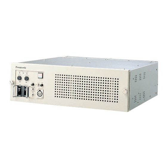
Camera Control Unit
Model AK-HCU931P
Ca me ra
Co ntr ol
Un it
Advertisement
Table of Contents

Related Manuals for Panasonic AK-HCU931


Summary of Contents for Panasonic AK-HCU931
-
Page 1: Camera Control Unit
CAB LE OPE N SHO RT ALA RM FUS E TAL LY/C ALL 125 V 5A FUS E 250 V 5A LEV EL MA IN HEA D PO PGM 1 WE R PGM 2 SYS TEM P U S H PRI VAT E Before attempting to connect, operate or adjust this product, please read these instructions completely. -
Page 2: Safety Precautions
Safety precautions CAUTION RISK OF ELECTRIC SHOCK DO NOT OPEN CAUTION: TO REDUCE THE RISK OF ELECTRIC SHOCK, DO NOT REMOVE COVER (OR BACK). NO USER SERVICEABLE PARTS INSIDE. REFER TO SERVICING TO QUALIFIED SERVICE PERSONNEL. The lightning flash with arrowhead symbol, within an equilateral triangle, is intended to alert the user to the presence of uninsulated “dangerous voltage”... -
Page 3: Table Of Contents
Contents Safety precautions ............2 Overview . -
Page 4: Parts And Their Functions
Parts and their functions $ Camera control unit front panel CABLE TALLY/CALL OPEN SHORT ALARM FUSE FUSE 125V 5A 250V 5A < LEVEL PGM 1 MAIN HEAD POWER PGM 2 > SYSTEM P U S H PRIVATE 1 CCU power switch [MAIN] This is the power switch of the camera control unit (CCU). -
Page 5: Camera Control Unit Rear Panel
Parts and their functions $ Camera control unit rear panel RET1 RET2 RET3 SDI INPUT RET1 RET2 RET3 SDI INPUT WFM1 WFM2 OUTPUT P U S H COMMUNICATION CH–1 A Optical fiber connector FXW.3K.93C.CLM made by LEMO Function Polarity Signal flow Optical fiber CAM#CCU CCU#CAM... - Page 6 Parts and their functions $ Camera control unit rear panel RET1 RET2 RET3 SDI INPUT RET1 RET2 RET3 SDI INPUT WFM1 WFM2 OUTPUT P U S H COMMUNICATION CH–1 J SDTV picture monitor video output connectors [PM 1, 2] These connectors (BNC) are for outputting the video signals which are to be displayed on the SDTV picture monitor.
- Page 7 Parts and their functions $ Camera control unit rear panel RET1 RET2 RET3 SDI INPUT RET1 RET2 RET3 SDI INPUT WFM1 WFM2 OUTPUT P U S H COMMUNICATION CH–1 Q RTS input connector [RTS IN] The RTS system is connected to this connector. The microphone level is 4 dBm/200 RTS input connector (HA16PRK-3S made by Hirose)
- Page 8 Parts and their functions $ Camera control unit rear panel RET1 RET2 RET3 SDI INPUT RET1 RET2 RET3 SDI INPUT WFM1 WFM2 OUTPUT P U S H COMMUNICATION CH–1 W Waveform monitor control connector [WFM CTL] This connector is used for controlling the waveform monitor. Since the interface is different, first check the WFM setting on the SYSTEM menu of the ROP or MSU before connect- ing the waveform monitor.
- Page 9 Parts and their functions $ Camera control unit rear panel RET1 RET2 RET3 SDI INPUT RET1 RET2 RET3 SDI INPUT WFM1 WFM2 OUTPUT P U S H COMMUNICATION CH–1 Y ROP connector The remote operation panel (ROP) is connected to this connector.
- Page 10 Parts and their functions $ Camera control unit rear panel RET1 RET2 RET3 SDI INPUT RET1 RET2 RET3 SDI INPUT WFM1 WFM2 OUTPUT P U S H COMMUNICATION CH–1 \ Alarm connector [ALARM] This connector is for outputting the alarm signals to the external system when any problem with the supply volt- age has occurred inside the CCU or the CCU fan has stopped.
-
Page 11: Connections
Connections Connections for SD system Dedicated ROP cables (available as optional accessories) are used to connect the CCU connector on the ROP unit and the ROP connector on the rear panel of the CCU (this unit). After all the equipment has been connected, set the main power switch on the CCU to ON. Then turn on the camera’s power. - Page 12 Connections Connections for HD/SD system Dedicated ROP cables (available as optional accessories) are used to connect the CCU connector on the ROP unit and the ROP connector on the rear panel of the CCU (this unit). After all the equipment has been connected, set the main power switch on the CCU to ON. Then turn on the camera’s power.
-
Page 13: External Dimension Drawing
External dimension drawing... -
Page 14: Specifications
Specifications Power supply: AC 120 V Power consumption: 80 W (when unit is operated on its own) indicates safety information. Video input/output signals SD digital signal (D1) SD analog signal (VBS) HD digital signal (optional) HD analog signal (Y, Pb, Pr/GBR): Output only (optional) PROMPT signal (VBS): Input only Sync input signals HD reference signal (tri-level sync) - Page 16 PANASONIC BROADCAST & TELEVISION SYSTEMS COMPANY UNIT COMPANY OF MATSUSHITA ELECTRIC CORPORATION OF AMERICA Executive Office: One Panasonic Way 4E-7, Secaucus, NJ 07094 (201) 348-7000 EASTERN ZONE: One Panasonic Way 4E-7, Secaucus, NJ 07094 (201) 348-7621 Southeast Region: 1225 Northbrook Parkway, Ste 1-160, Suwanee, GA 30024 (770) 338-6835...
Need help?
Do you have a question about the AK-HCU931 and is the answer not in the manual?
Questions and answers