CAME ZL65 Installation Manual
Control panel for 24 v gearmotors
Hide thumbs
Also See for ZL65:
- Installation manual (128 pages) ,
- Installation manual (33 pages) ,
- Installation manual (27 pages)
Table of Contents
Advertisement
Advertisement
Table of Contents

Related Manuals for CAME ZL65


Summary of Contents for CAME ZL65
- Page 1 CONTROL PANEL FA01233-EN FOR 24 V GEARMOTORS ZL65 INSTALLATION MANUAL EN English...
-
Page 2: Intended Use
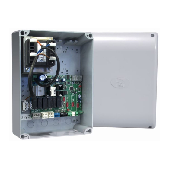
- connecting the ERLB emergency (blackout) operation and battery-recharging card. - connecting to the RIO-CONN card for confi guring Rio-series wireless accessories; - connecting the UR042 module for remotely managing CAME operators, using the CAME CLOUD-specifi c system. All connections and links are rapid-fuse protected. - Page 3 Dimensions (mm) Description of parts Line fuse 13. R700/R800 board connector Power supply terminals 14. Connector for the RIO-CONN card Terminals for signaling devices 15. RSE board connector Gearmotors with encoder terminals 16. Memory Roll card connector Control devices terminals 17.
- Page 4 RG58 Antenna max 10 m antenna Came Remote Protocol (CRP) UTP CAT5 max 1000 m If cable lengths diff er from those specifi ed in the table, establish the cable sections depending on the actual power draw of the connected devices and according to the provisions of regulation CEI EN 60204-1.
-
Page 5: Power Supply
INSTALLATION Fastening the control panel Fasten the control panel in a protected area using suitable screws and dowels Only use 6 x 70 mm cylinder-head screws. Drill through the pre-drilled holes (18 and 20 mm) under the control panel's base Be careful not to damage the control board. - Page 6 Connecting gearmotor with encoder M1 N1 ENC1 M2 N2 ENC2 (M2) 24 V DC gearmotor with encoder, delayed in closing. (M1) 24 V DC gearmotor with encoder, delayed in opening. Warning device 10 11 E 5 Gate-open signal output. (Contact rated for 24 V AC/DC - 3 W max). See function F 10. Output for connecting either fl...
- Page 7 Safety devices Photocells Confi gure contact CX or CY (NC), input for safety devices, such as photocells, that comply with EN 12978 provisions. See CX input functions (Function F2) or CY (Function F3) in: - C1 reopening during closing. when the gate is closing, opening the contact causes the inversion of movement until opening is complete;...
- Page 8 E 17 error message is displayed. RIO-CONN RIO-EDGE RIO-CELL RIO-LUX Connection with Came Remote Protocol (CRP) Fit the RSE card. A - A 1 2 3P 7 10 TS 2 CX CY A B GND S1 GND A B B - B...
- Page 9 Description of programming commands 8 8 8 Display The ENTER key is for: The ESC button is for: - entering menus; - exiting menus; - confi rming or memorizing set values. - cancelling changes. The < > keys are for: - moving from one item to another;...
- Page 10 Functions map Total stop function (1-2) Function associated to input 2-CX Function associated to input 2-CY Safety test function Maintained action function Control mode on 2-7 Control mode on 2-3P Obstruction detection with motor idle function F 10 Function associated to the open gate signal or electric lock enabling. F 11 Encoder exclusion F 12...
- Page 11 Functions menu IMPORTANT! Start programming by fi rst performing the MOTOR TYPE (A 1), F 46 MOTOR NUMBERS and A3 TRAVEL CALIBRATION functions. Programming the features is to be done when the operator is stopped. You can memorize up to 25 users. F 1 Total stop [1-2] OFF= Deactivated (default) / ON= Activated NC input –...
- Page 12 F 10 Open-gate signal or 0 = lit when gate is open or moving (default) electric lock enabling 1 = when opening it fl ashes intermittently every half-second, when closing it fl ashes intermittently every second, stays lit when gate is open, stays off when gate is closed 2 = enabled electric lock.
- Page 13 F 22 Working time 5 = 5 seconds /… / 120 = 120 seconds (default) /… / 180 = 180 seconds. Motors working time, when opening and closing. Adjustable between 5 and 180 seconds. F 23 Delayed opening time 0 = 0 seconds /… / 2 = 2 seconds (default) /… / 10 = 10 seconds. After an opening command, the M1 gearmotor starts delayed.
- Page 14 0 = 1200 Baud / 1 = 2400 Baud / 2 = 4800 Baud / 3 = 9600 Baud / 4 = 14400 Baud / 5 = 19200 Baud / 6 = 38400 Baud / 7 = 57600 Baud / 8 = 115200 Baud For setting the communication speed used in the CRP (Came Remote Protocol) connection system.
- Page 15 F 65 Wireless input RIO-EDGE OFF= Deactivated (default) / 7 = P7 / 8 = P8 [T1] RIO-EDGE wireless safety device associated to any function chosen among those available: P7 = reopening during closing, P8 = reclosing during opening. For programming, see the instructions that come with the accessory. This function only appears is the control board has been fi...
- Page 16 A 3 Travel calibration OFF= Disable / ON= = Activate Automatic calibration of the gate-leaf run (see the TRAVEL CALIBRATION paragraph). This function appears only is the Encoder function is activated. A 4 Resetting parameters OFF= Disable / ON= = Activate Warning! The default settings are restored and the travel calibration deleted.
- Page 17 Travel calibration Before calibrating the gate travel, position the gate half-way, check that the maneuvering area is clear of any obstruction and check that there are mechanical opening and closing stops. The mechanical end-stops are obligatory. Important! During calibration, all safety devices will be disabled. Select A 3.
- Page 18 When entering/deleting users, the fl ashing numbers that appear, are numbers that can be used for other users you may wish to enter (maximum 25 users). Entering a user with an associated command User Associated command Select U 1 Press ENTER to confi rm. Select a command to associate to the user.
- Page 19 Memory Roll Card To memorize user data and confi gure the system, to then reuse them with another control board even on another system. After memorizing the data, it is best to remove the Memory Roll. Memory Roll. ILLUSTRATION OF THE SLOW-DOWN AND APPROACH AREAS AND POINTS The travel areas and slow-down and approach points are tested to comply with the parameters set forth by Technical Regulations EN 12445 and EN 12453 for impact force compatibility of moving gate leaves.
- Page 20 DO NOT DISPOSE OF IN NATURE! REFERENCE REGULATIONS The product complies to the reference regulations in eff ect. CAME S.p.A. Via Martiri Della Libertà, 15 31030 Dosson di Casier - Treviso - Italy tel. (+39) 0422 4940 - fax. (+39) 0422 4941...
Need help?
Do you have a question about the ZL65 and is the answer not in the manual?
Questions and answers